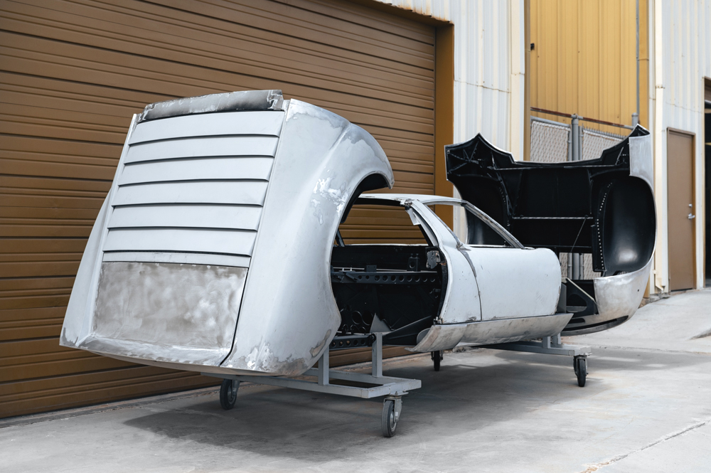
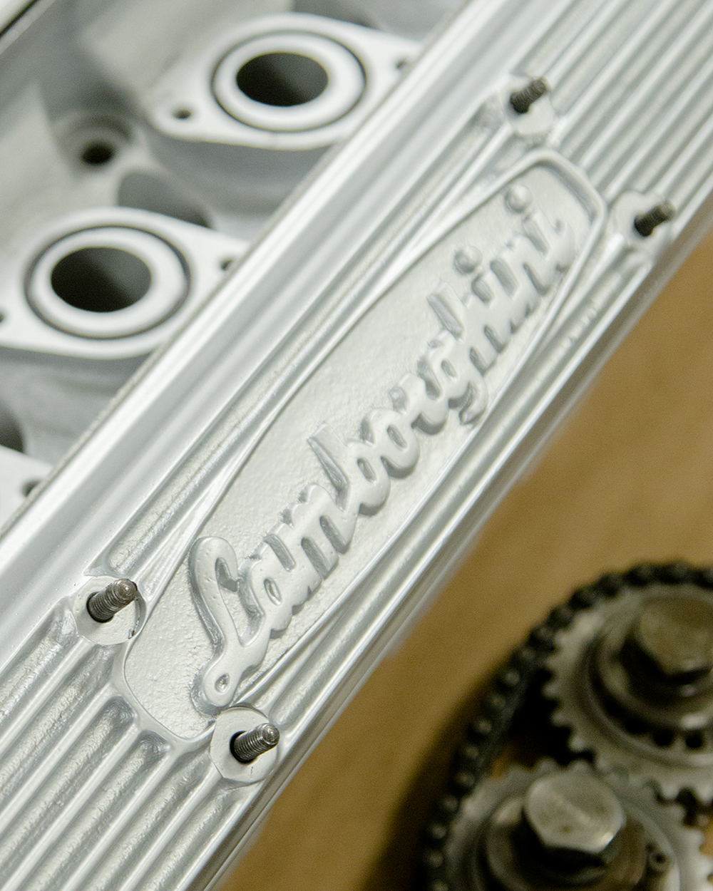
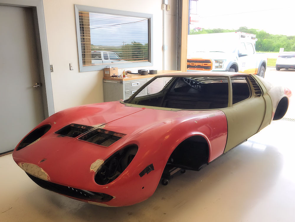
1967 Lamborghini Miura P400 (Topo) Total restoration
Restoration log by Dan Mooney
1967
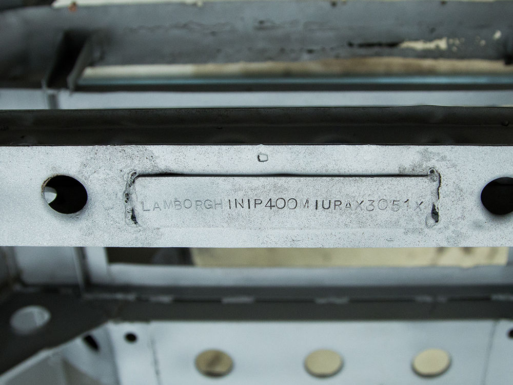
Lamborghini Miura - Chassis # 3051
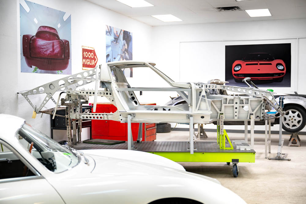
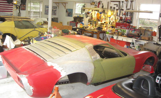
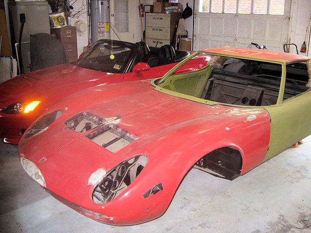
This Lamborghini
P400 (production # 36) has been
languishing in its current disassembled
state for almost 40 years.
Affectionately named 'Topo' by its
longtime owners, the car is currently
undergoing a total restoration in the
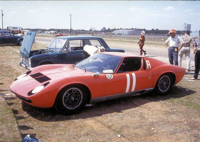
Team CJ Workshops. Purchased new by renowned gentleman
racer, oil heir and sportscar
personality Toly Arutunoff, 3051 has a
fascinating history. Toly ordered the
car while visiting the Lamborghini stand
at the 1965 Torino Motor Show, believing
it to be just the seventh Miura order
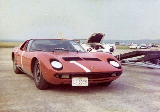
placed. Toly raced the car several times
shortly after taking delivery in the
summer of 1967, and also used it as his
daily driver for several years.
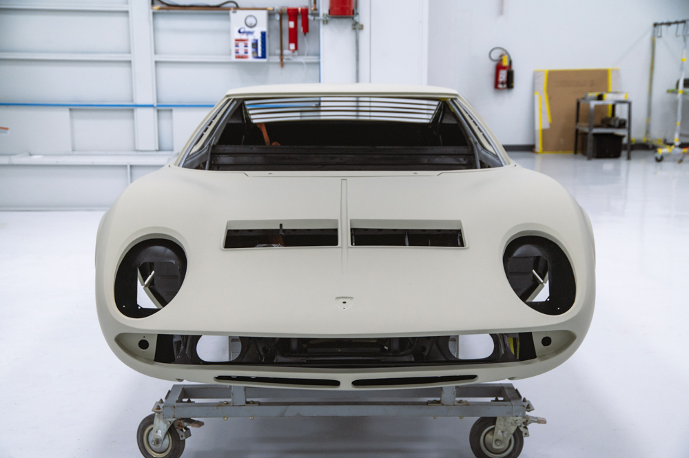
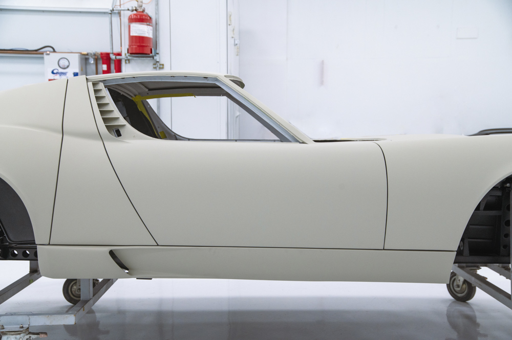
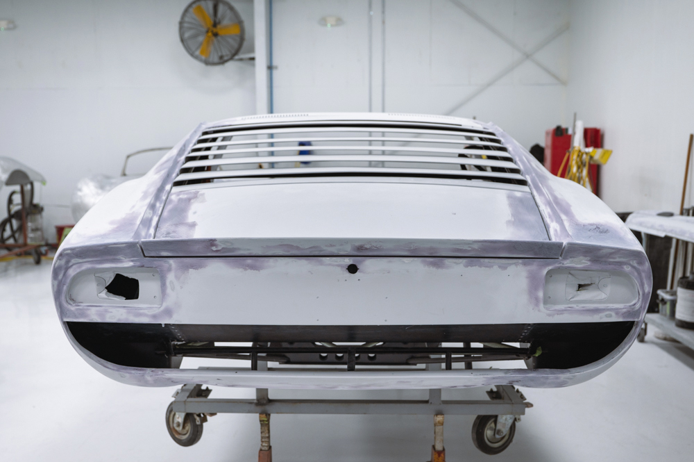
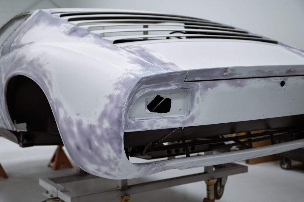
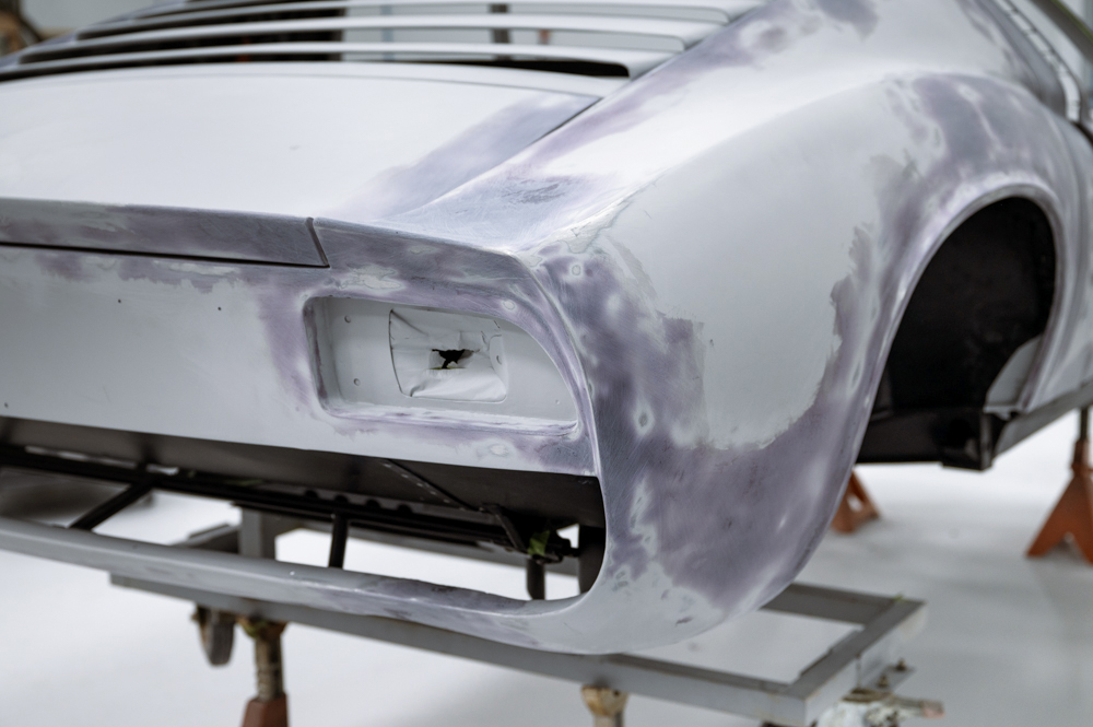
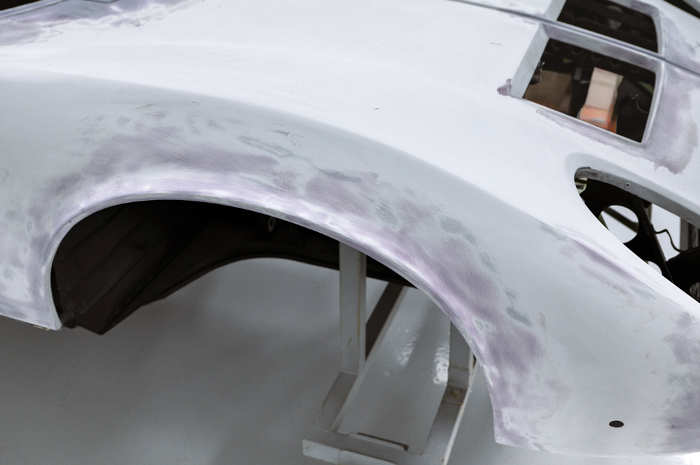
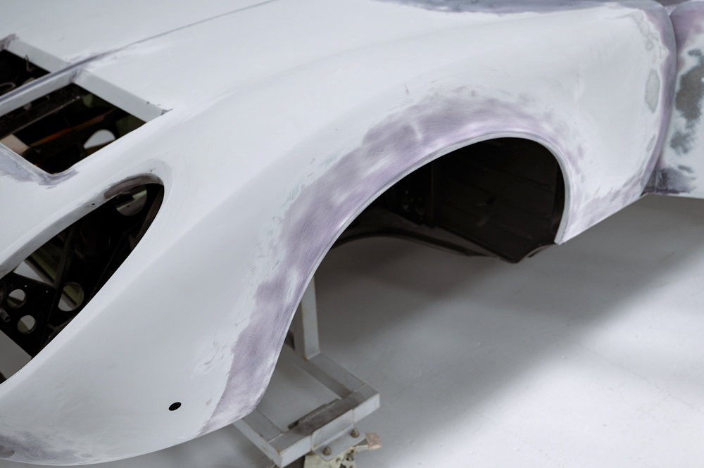
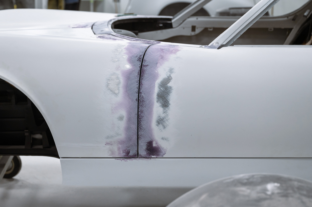
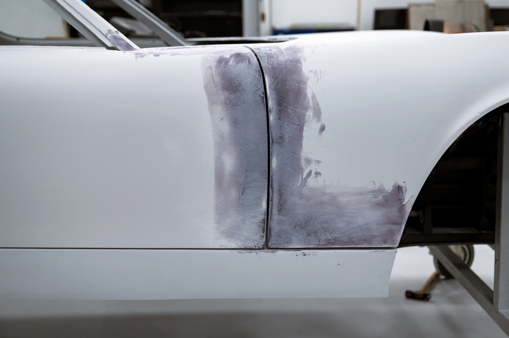
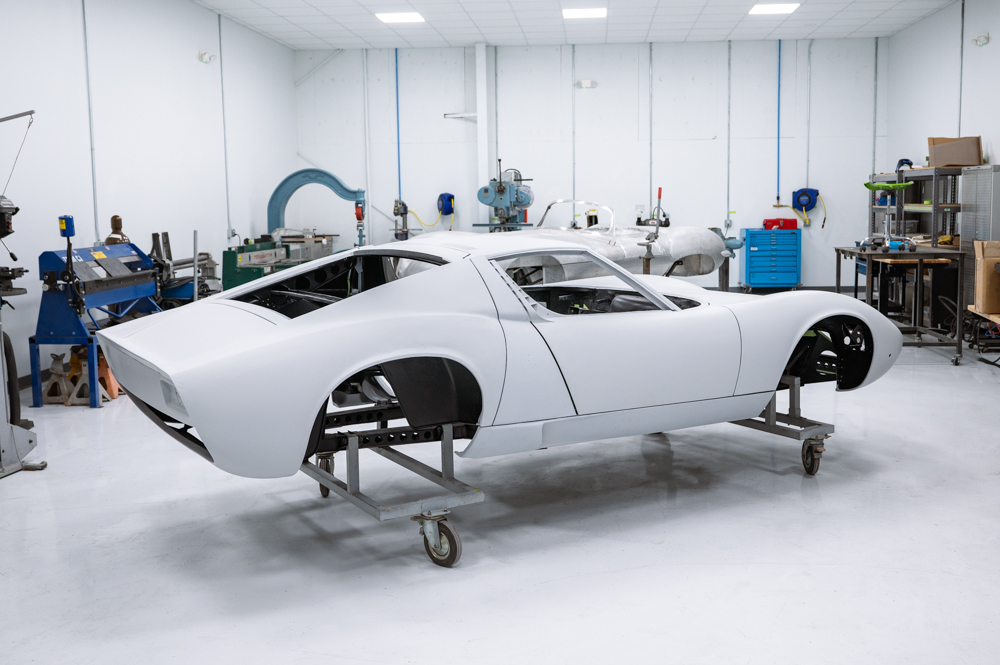
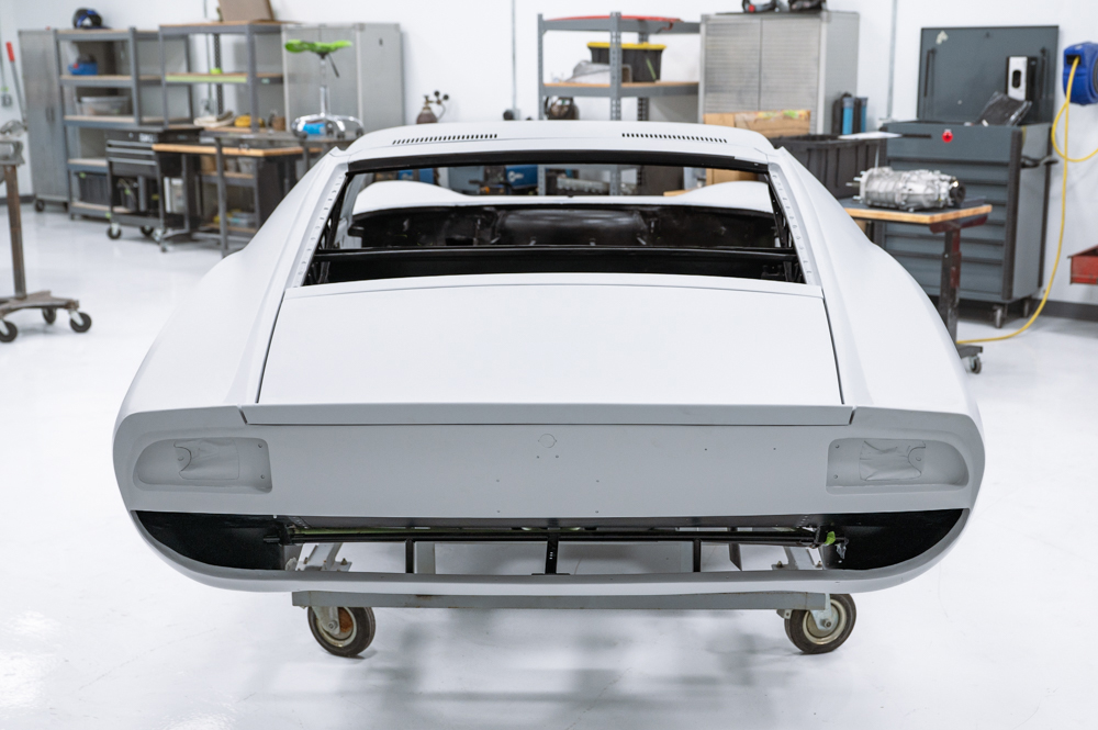
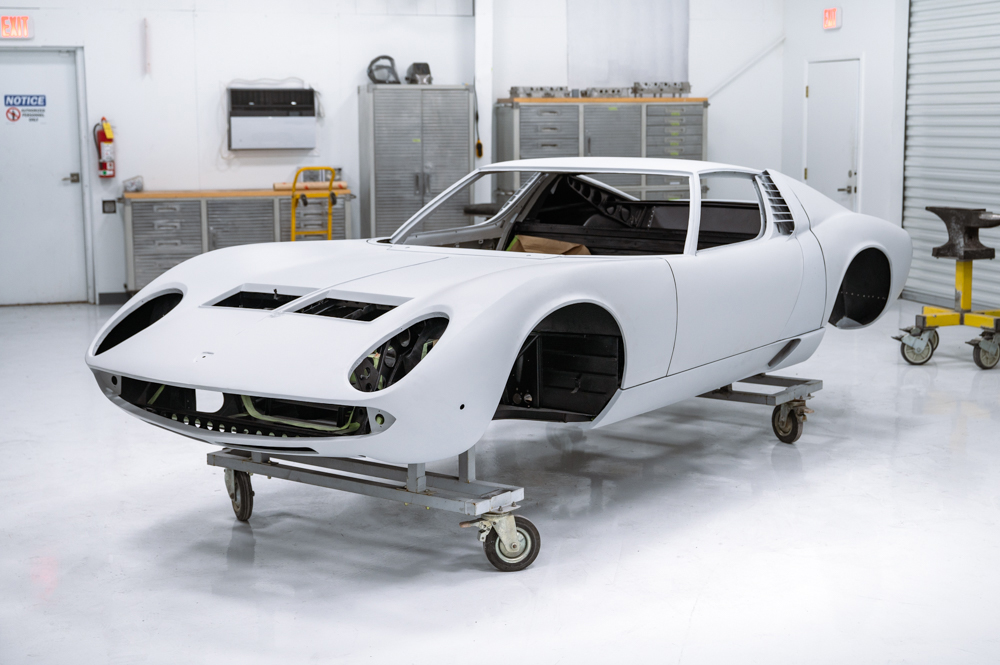
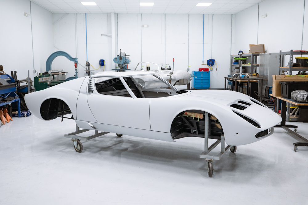
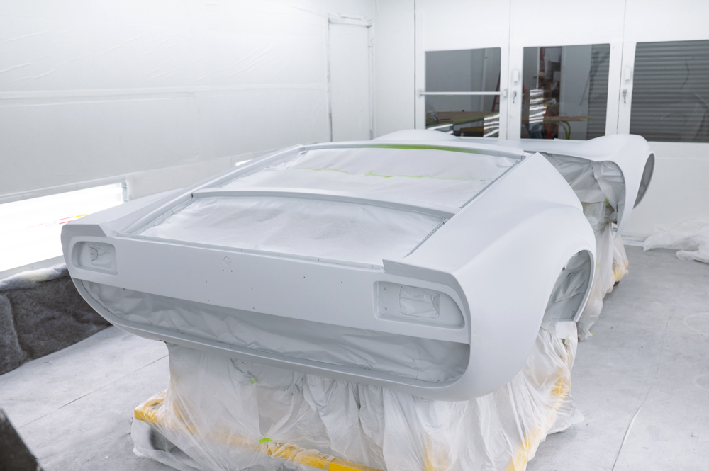
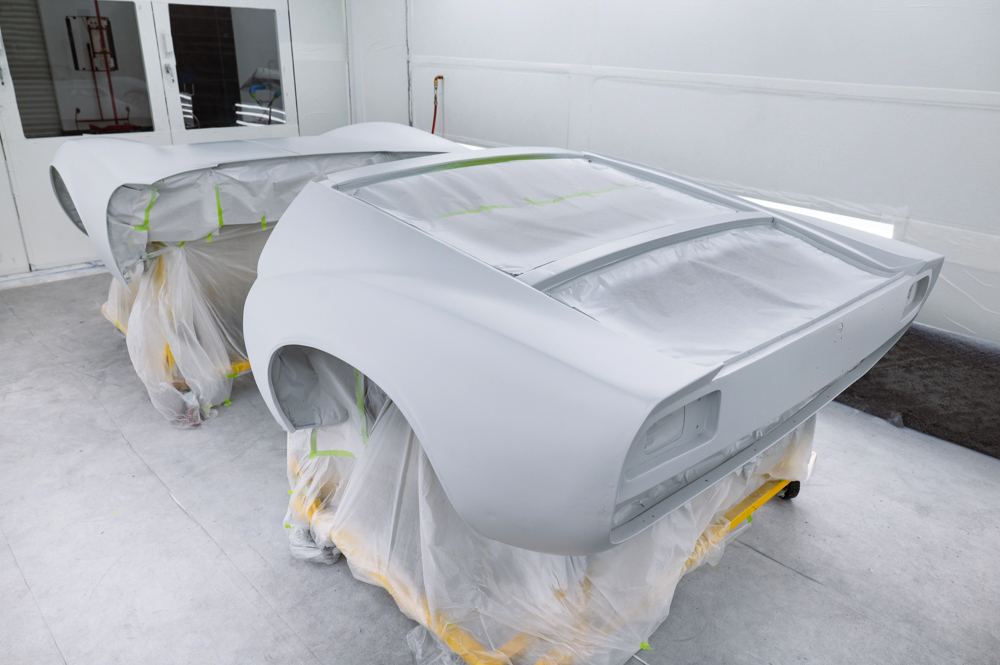
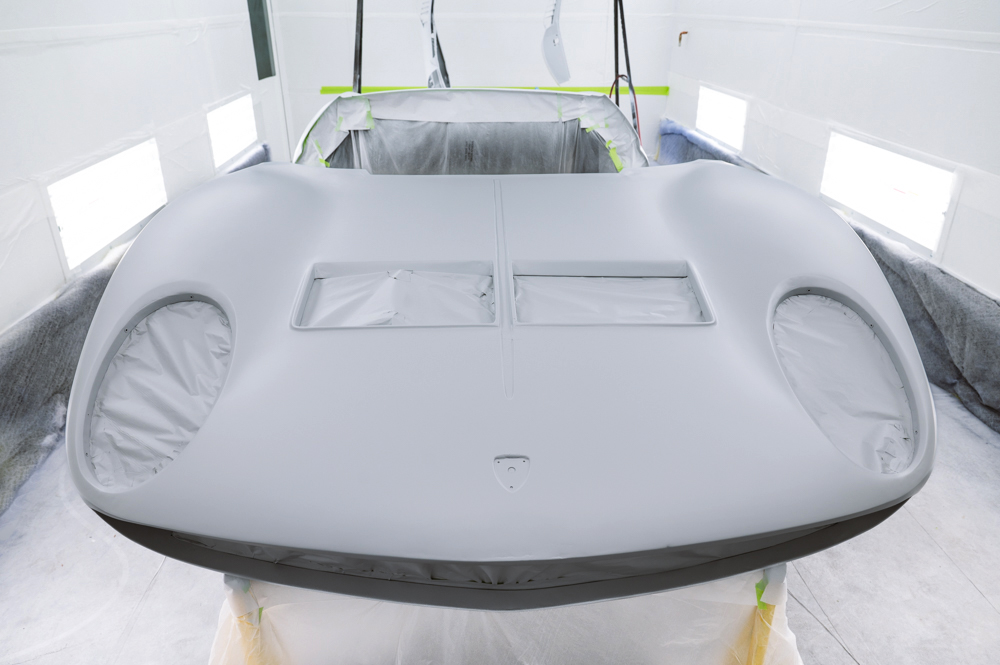
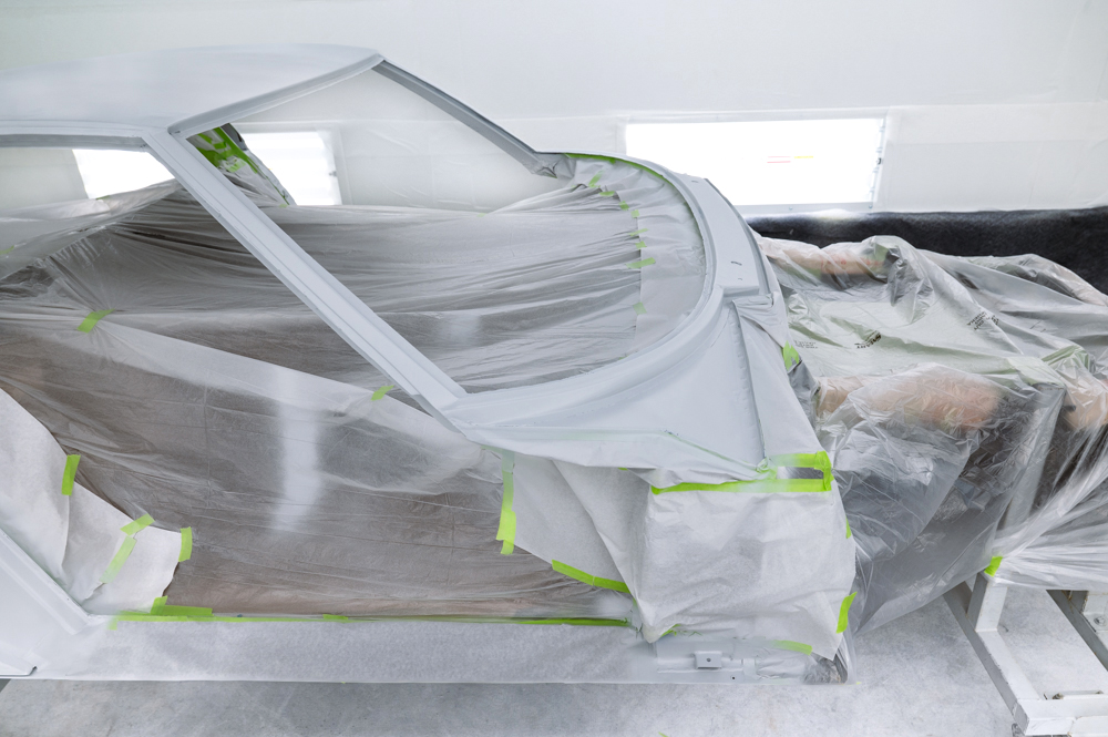
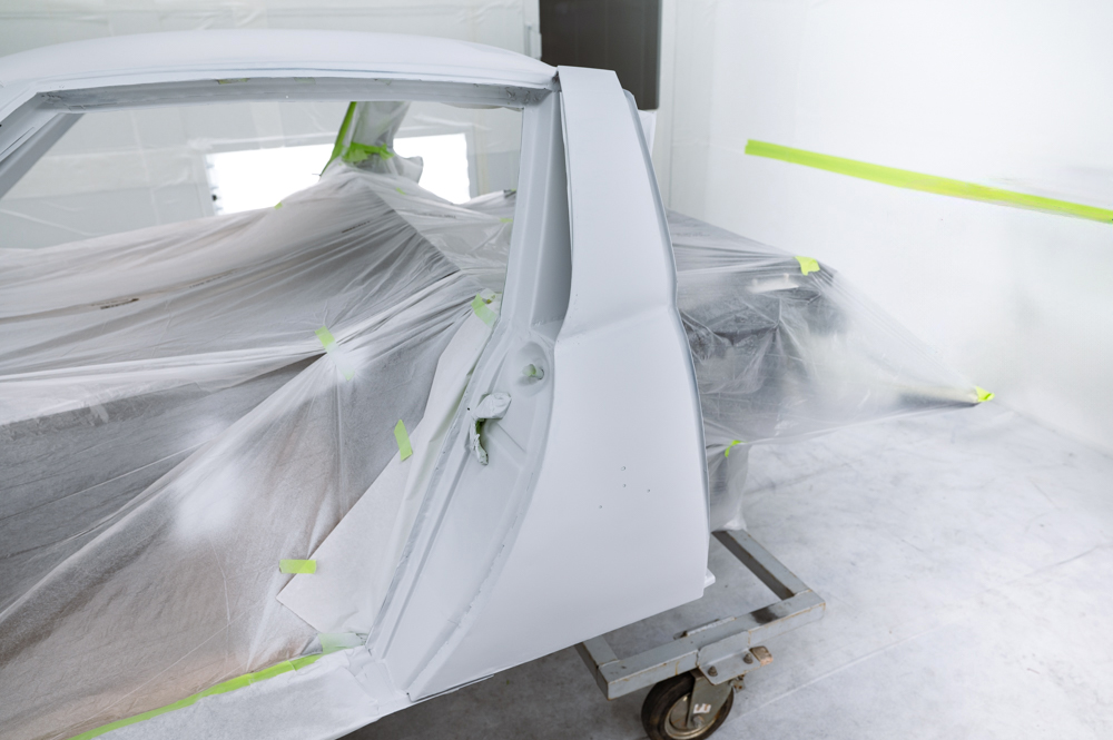
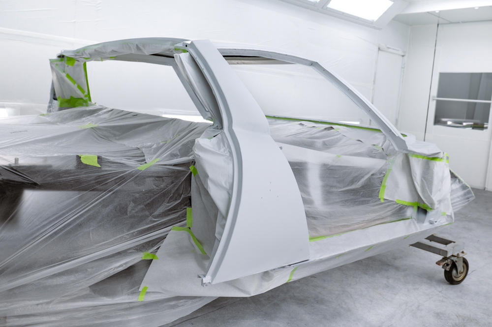
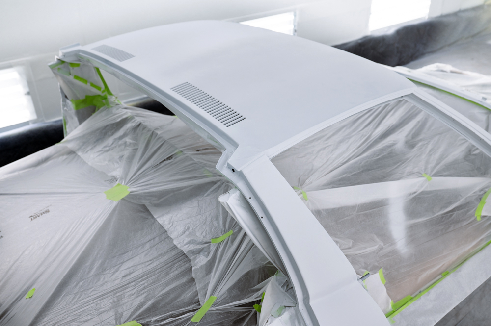
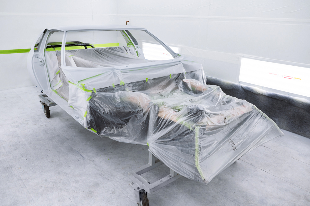
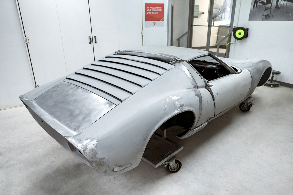
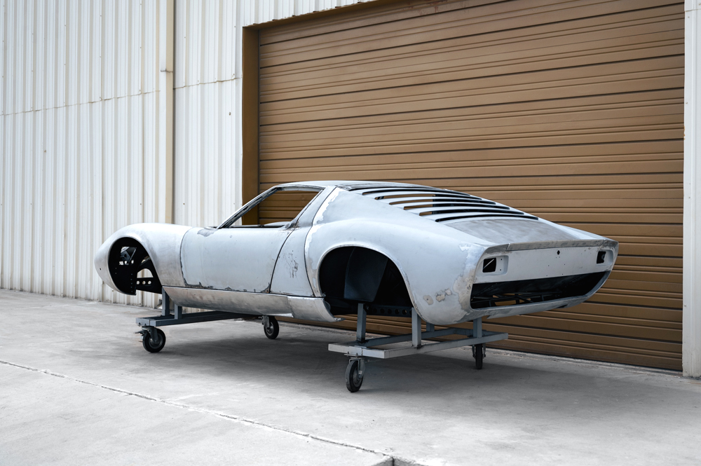
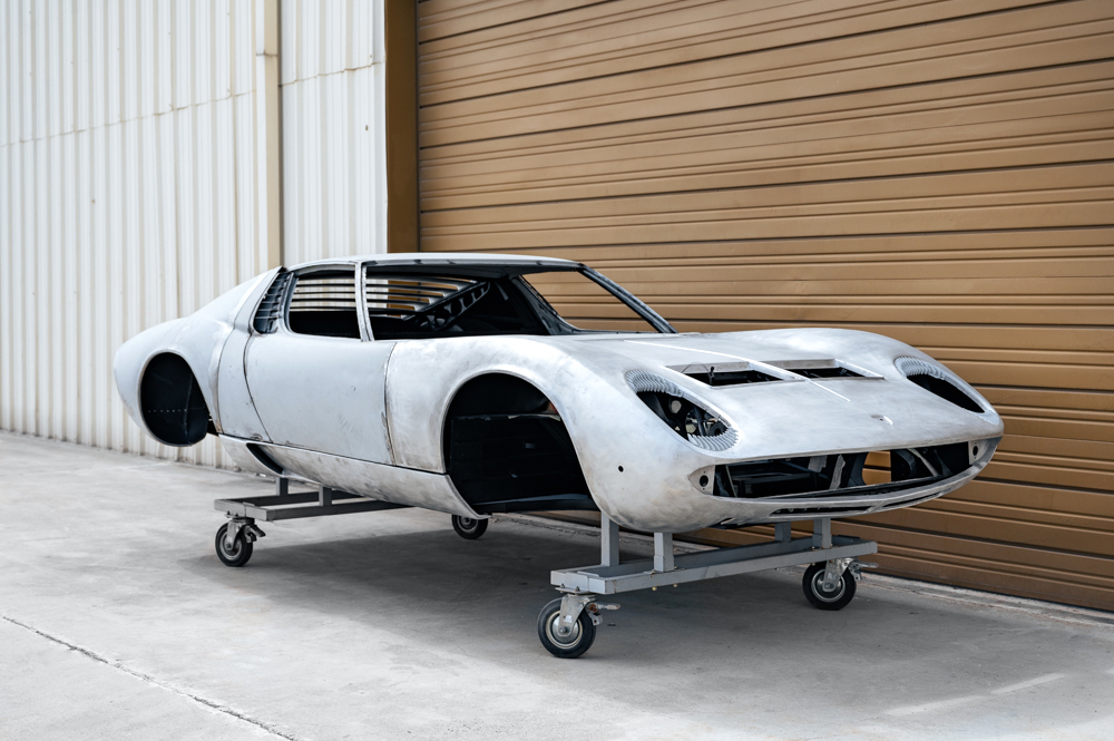
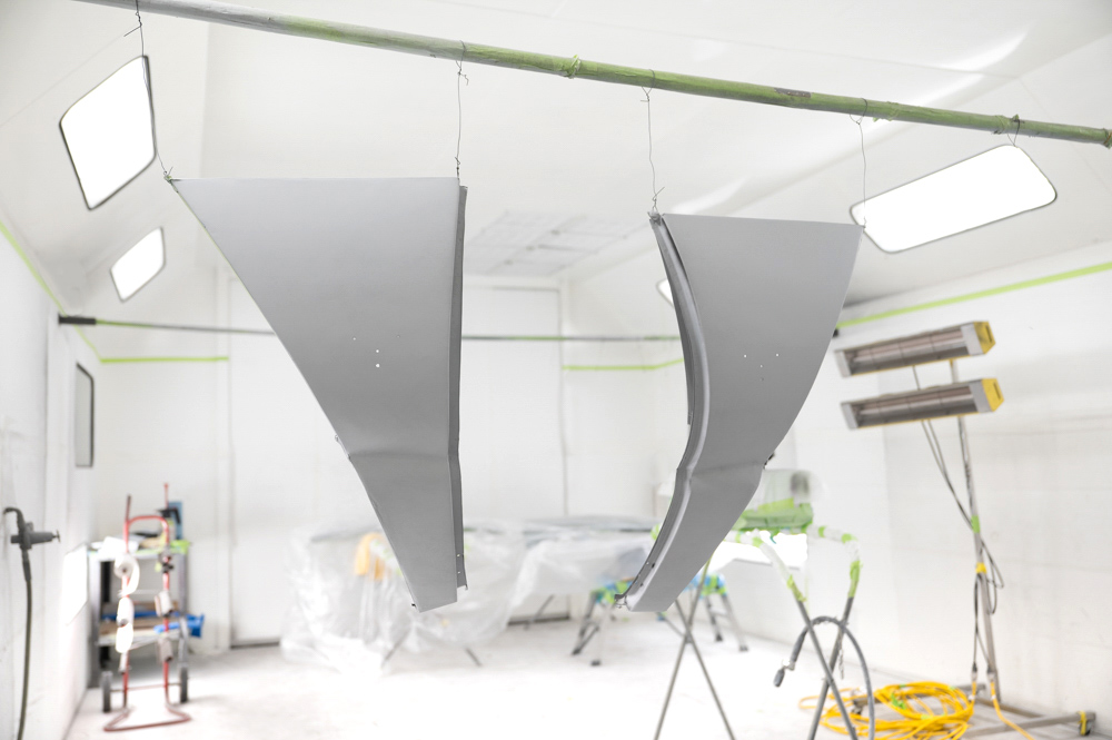
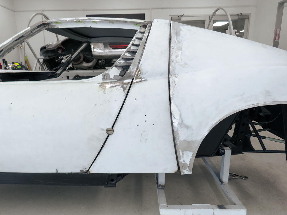
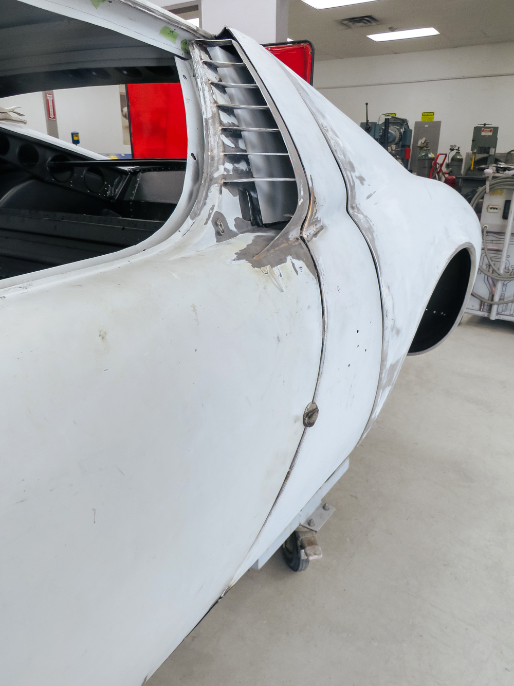
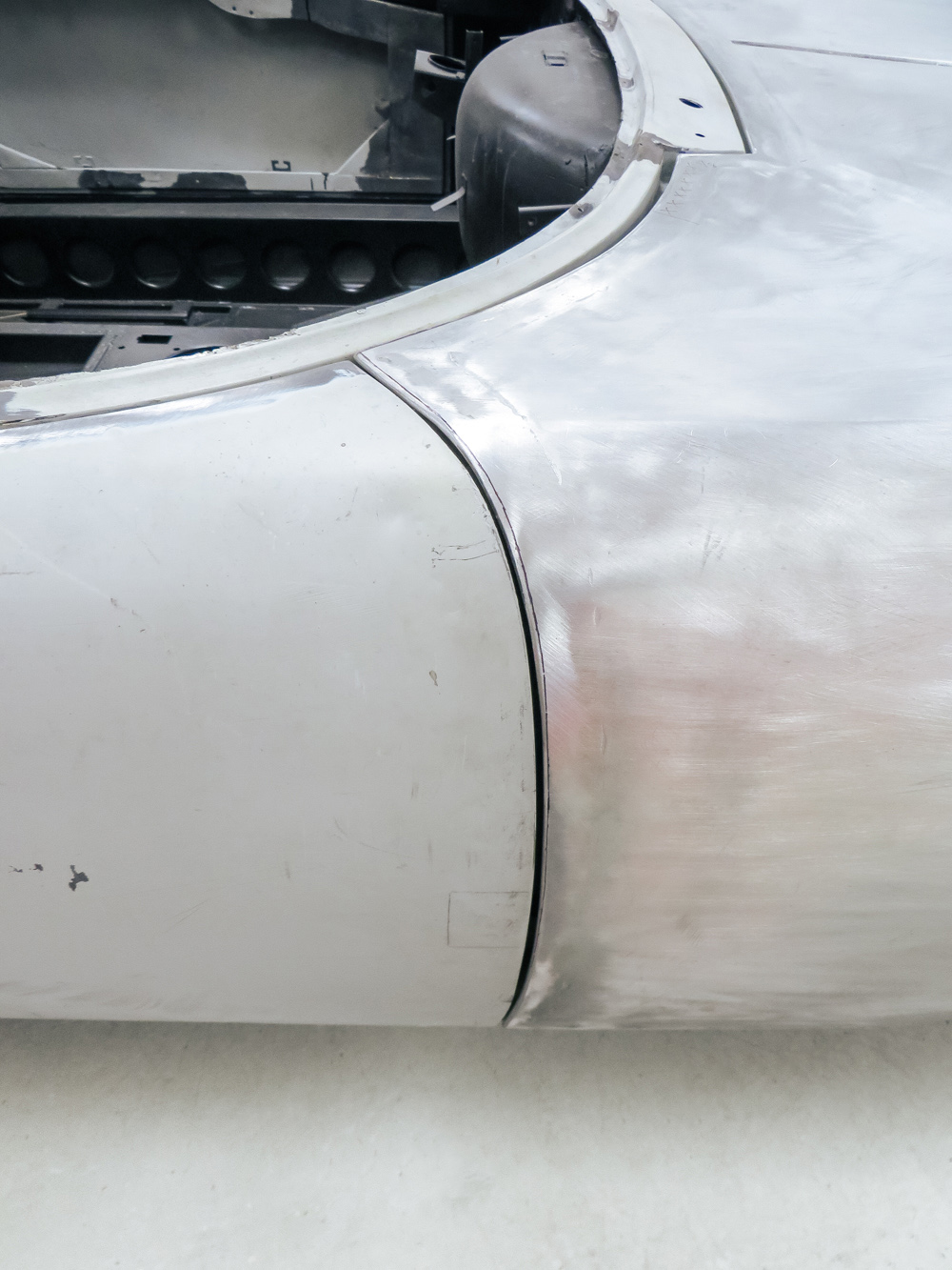
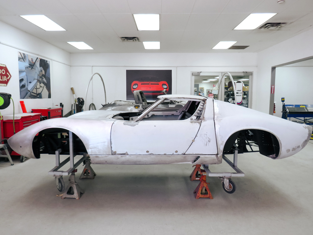
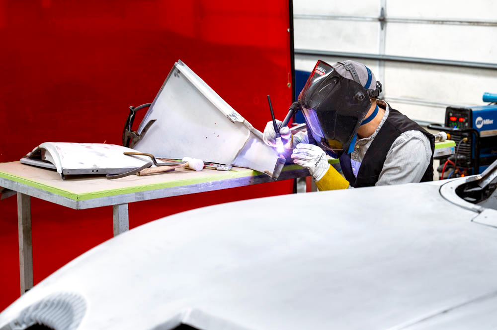
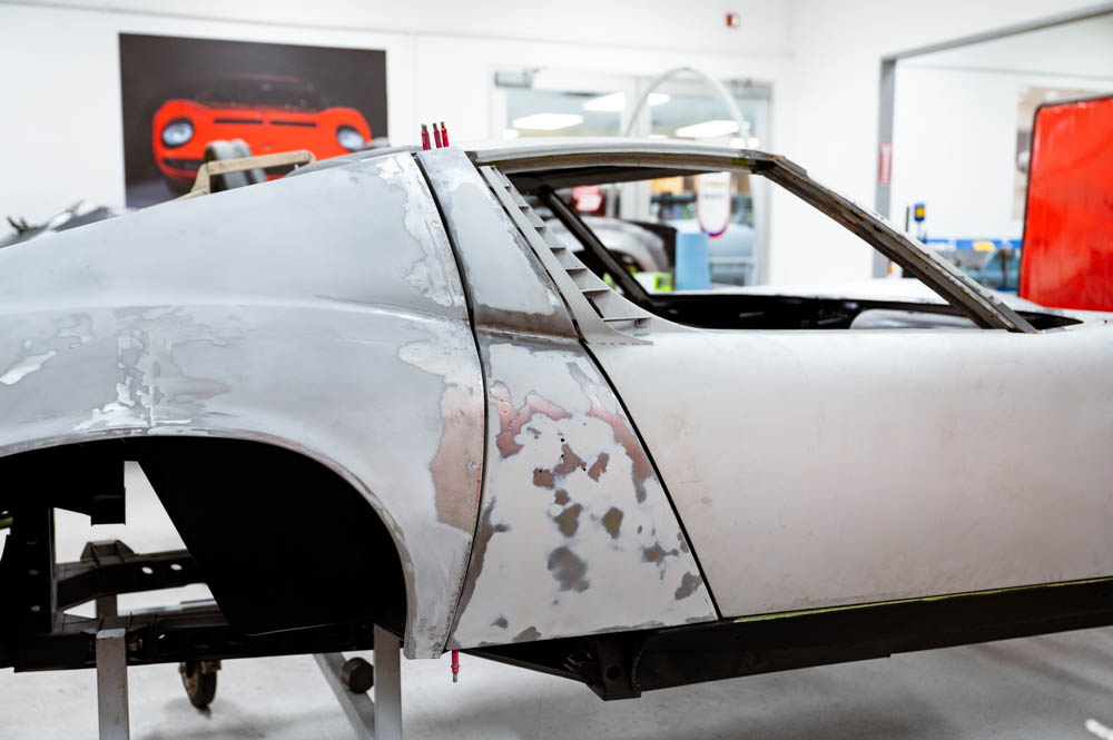
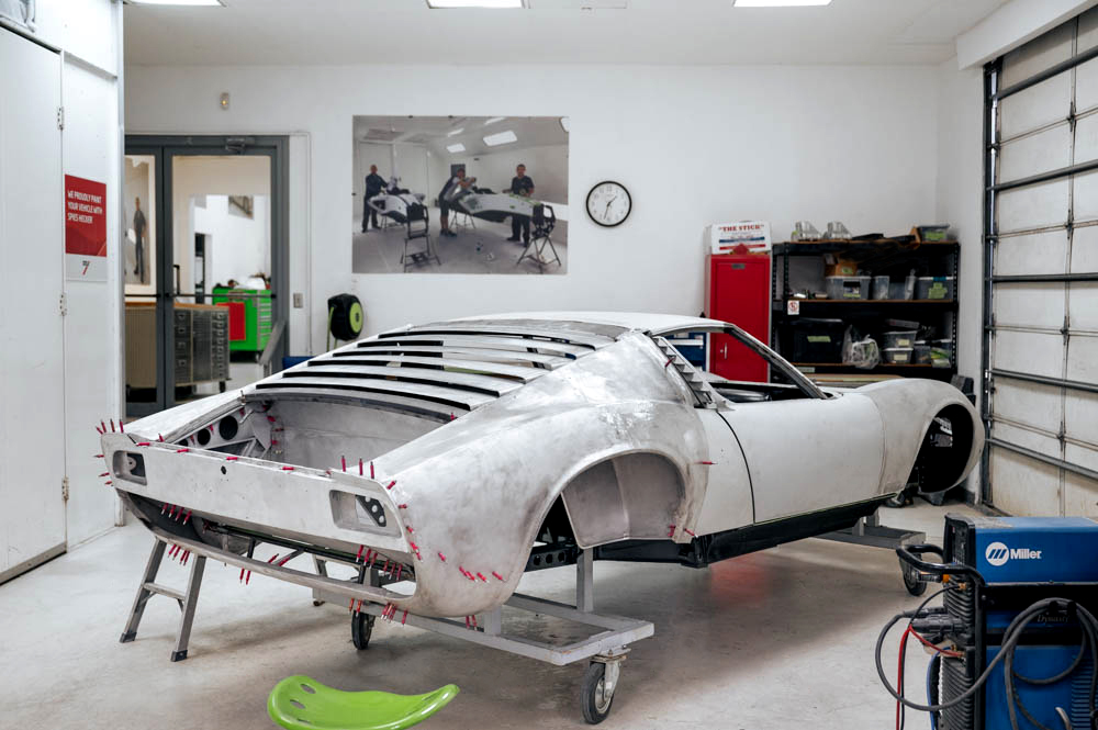
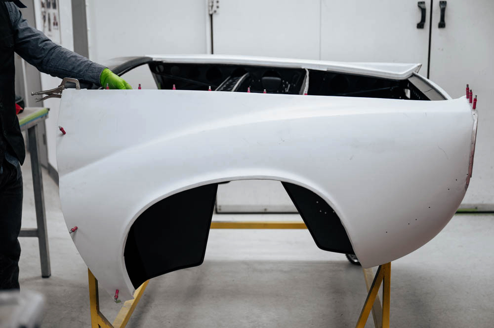
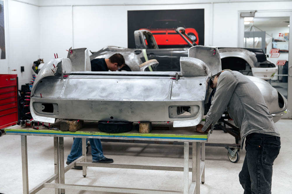
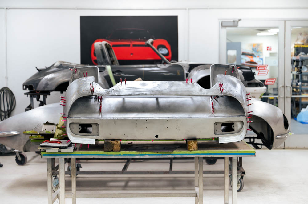
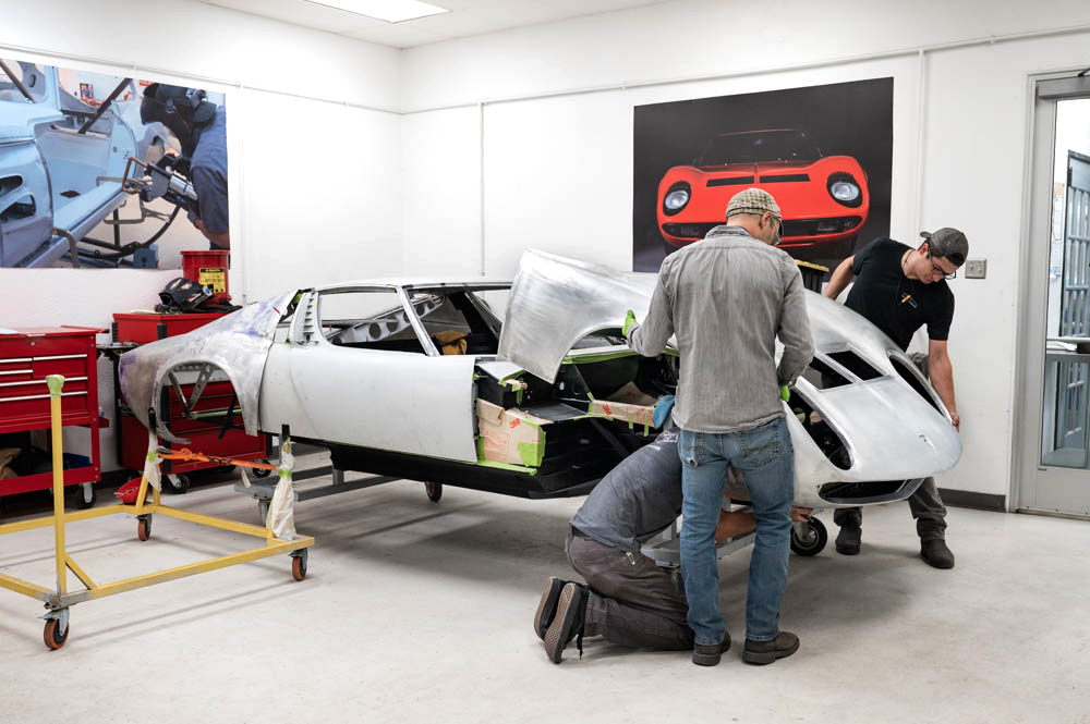
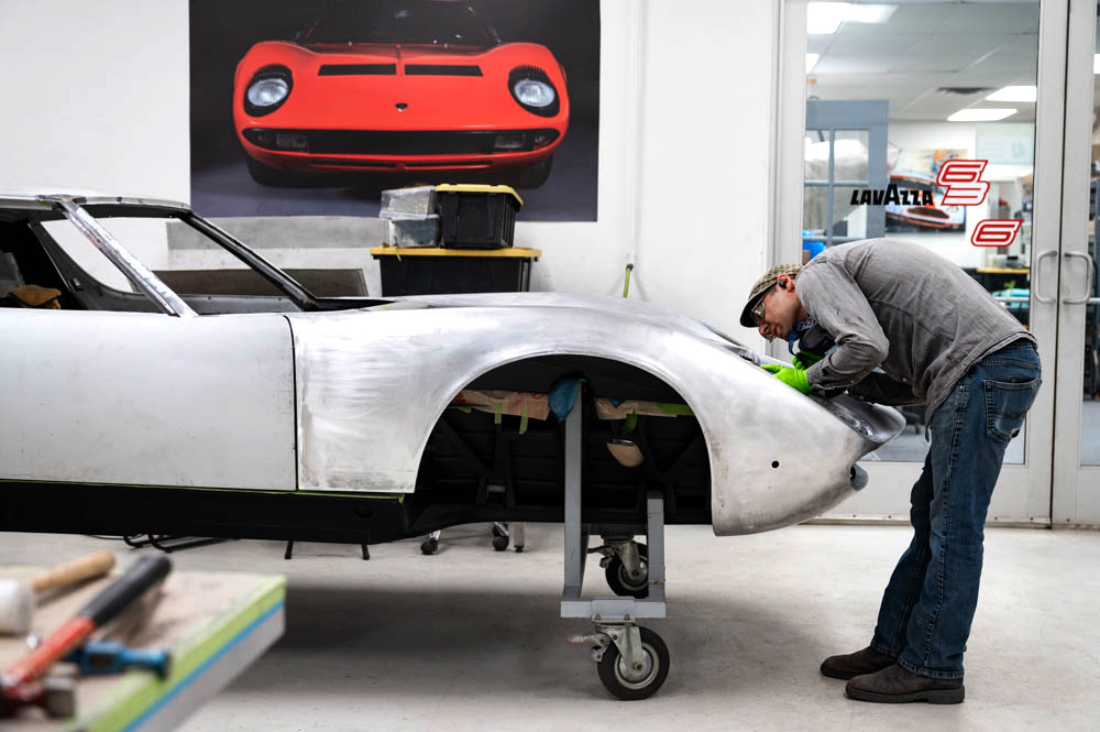
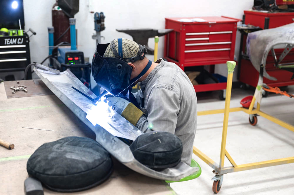
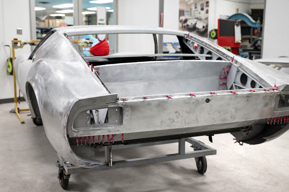
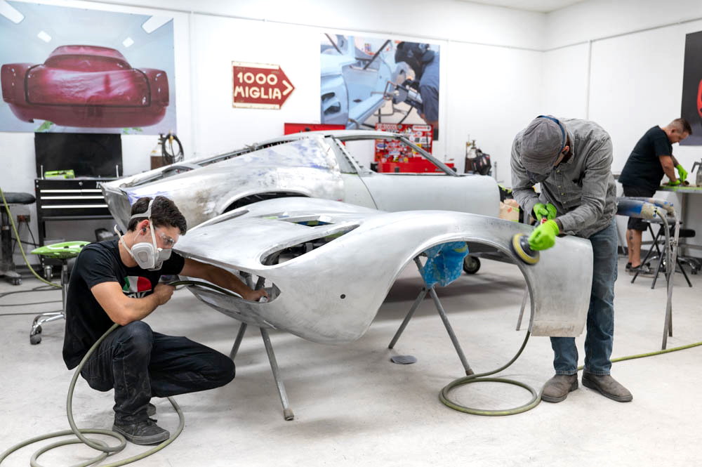
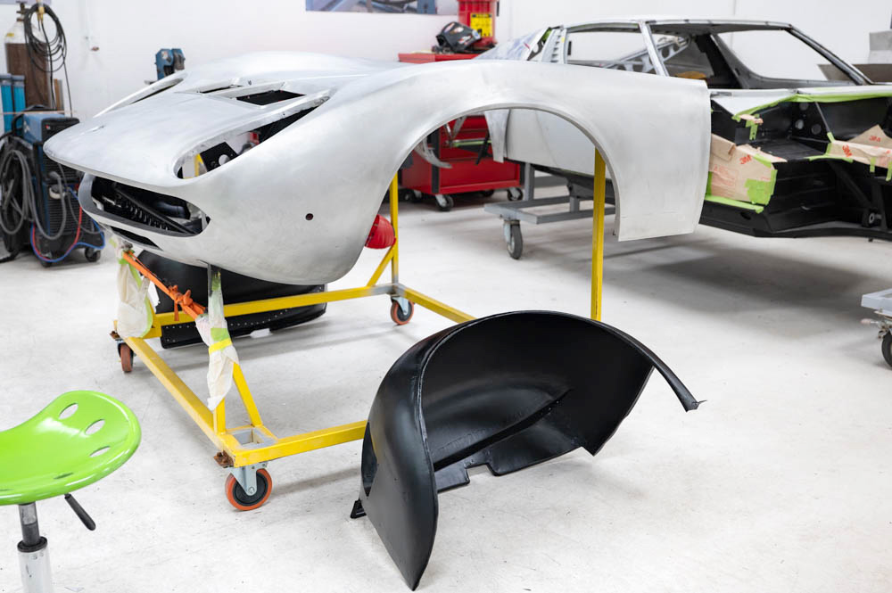
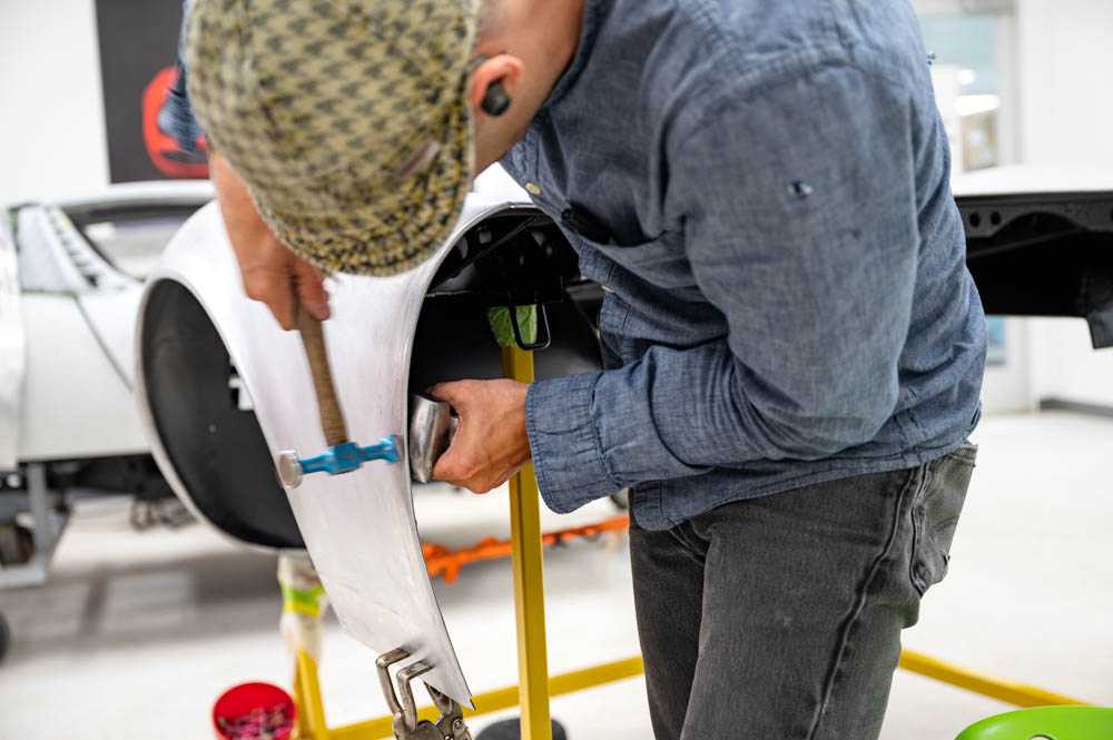
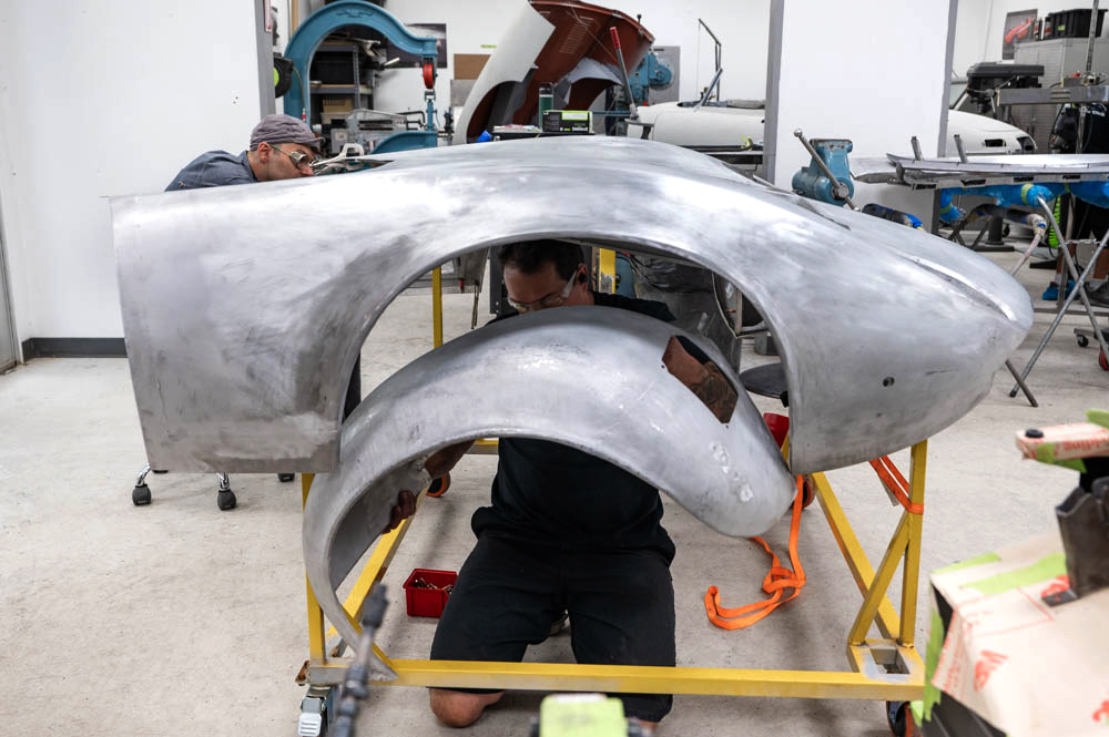
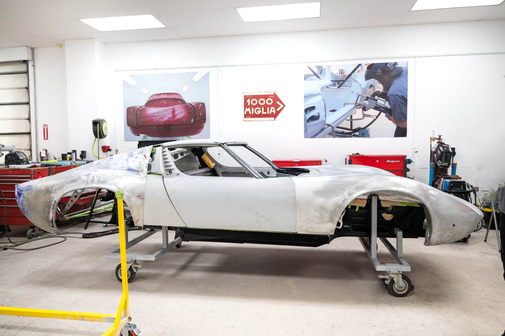
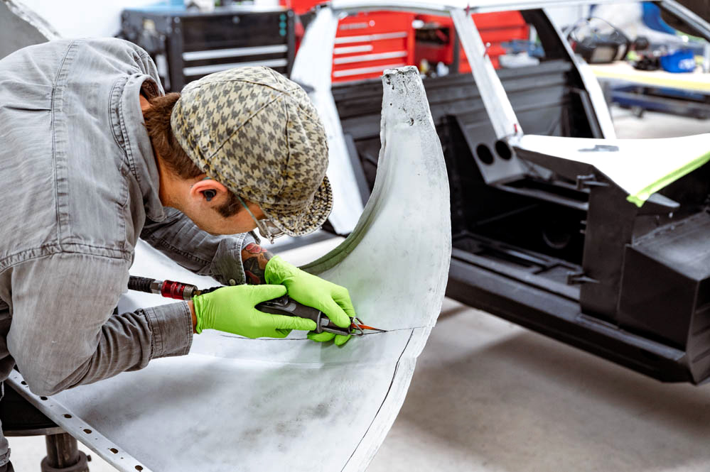
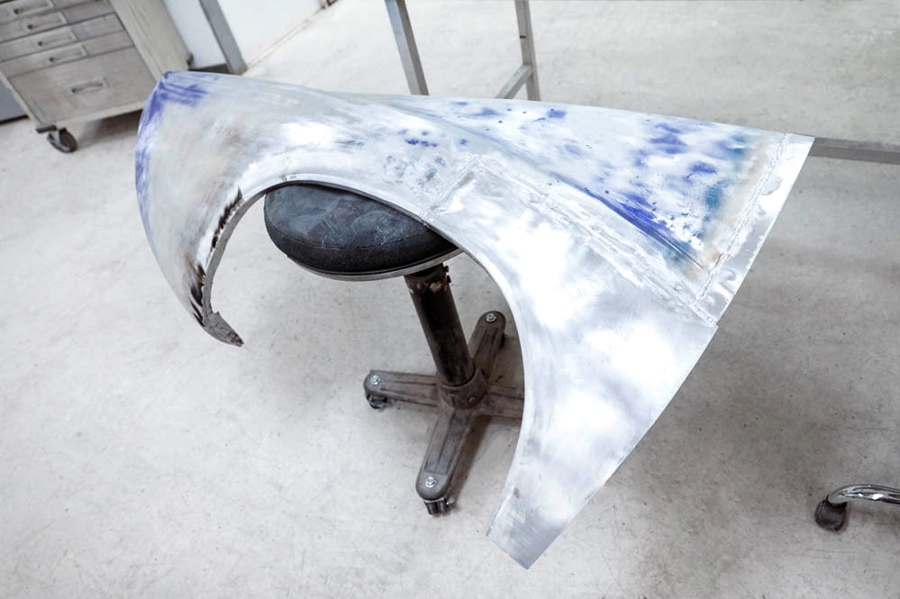
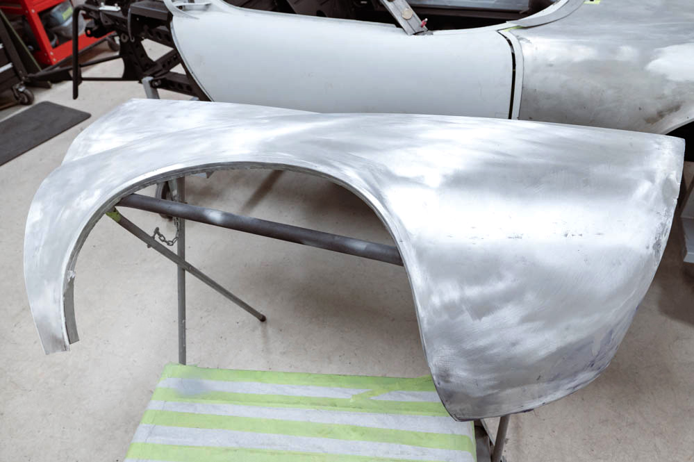
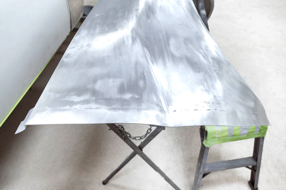
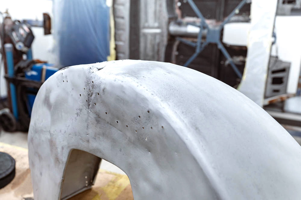
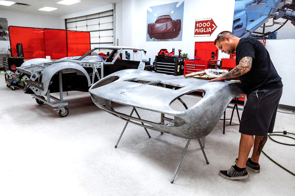
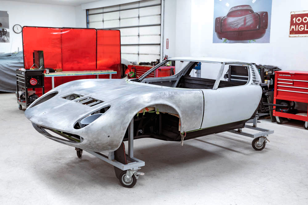
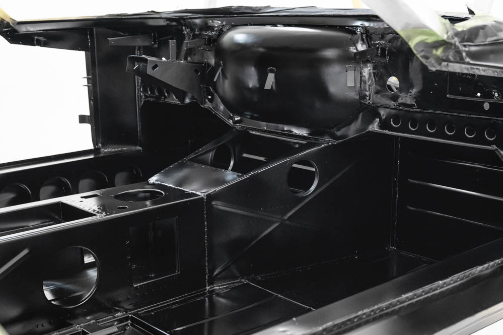
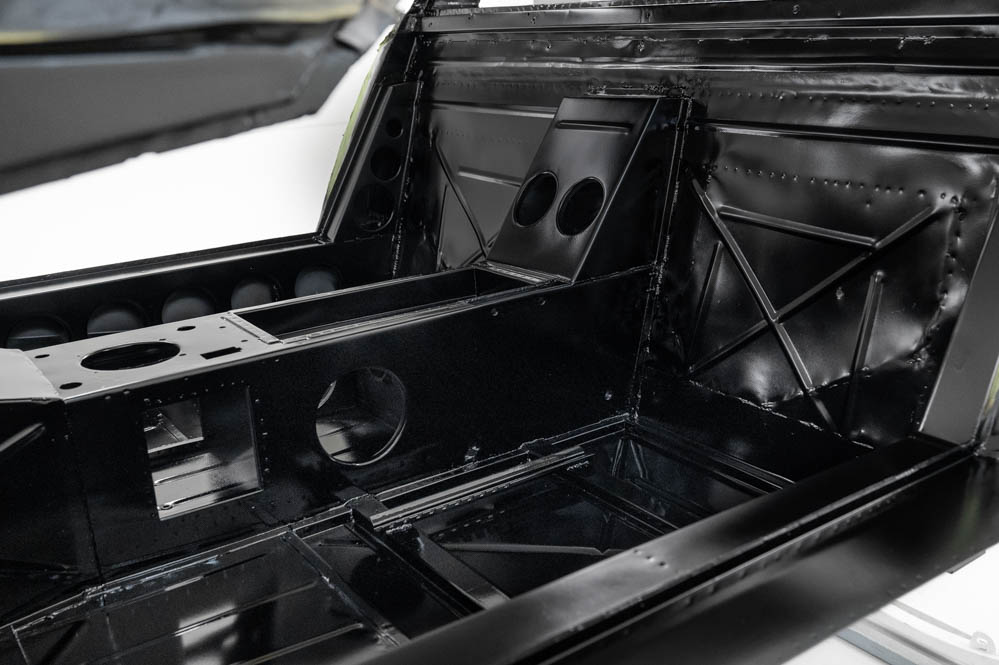
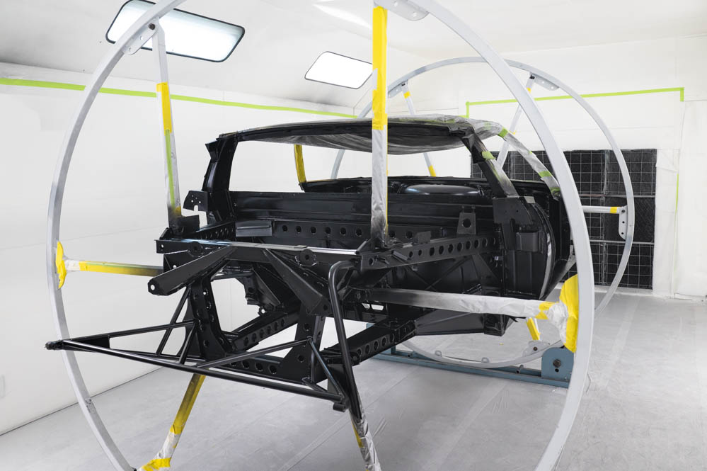
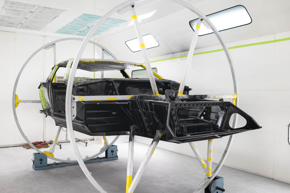
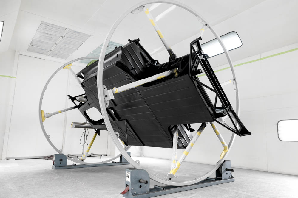
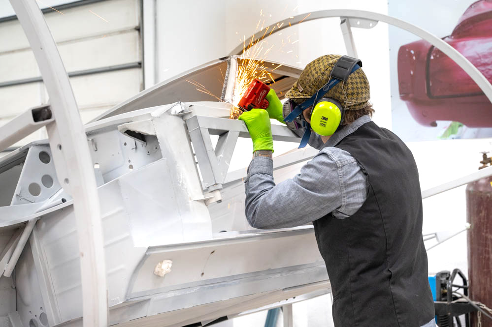
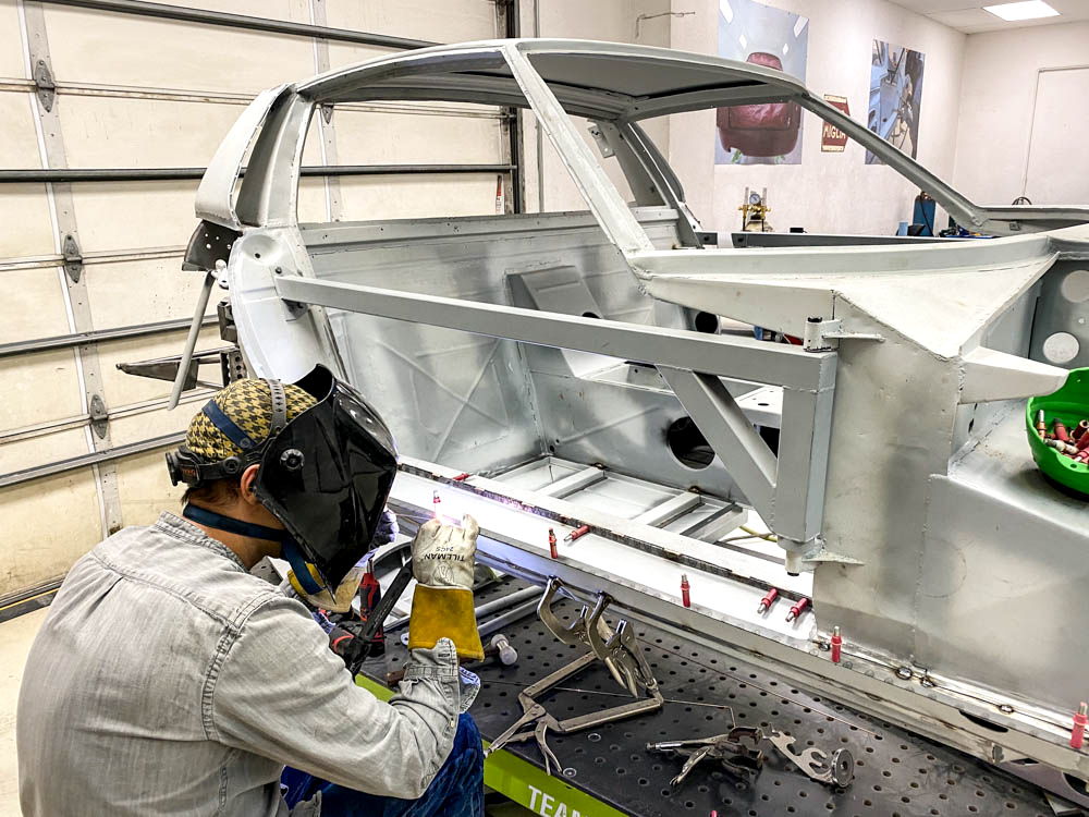
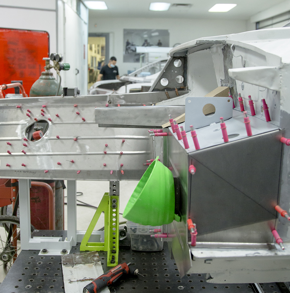
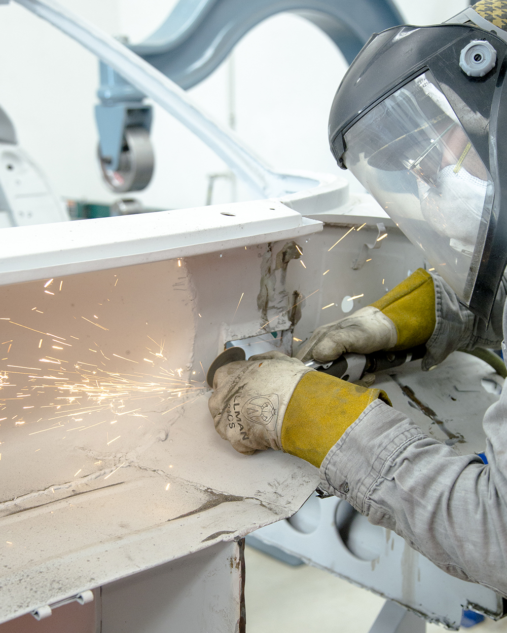
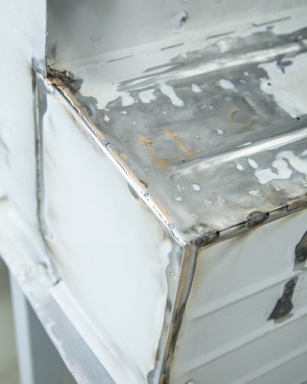
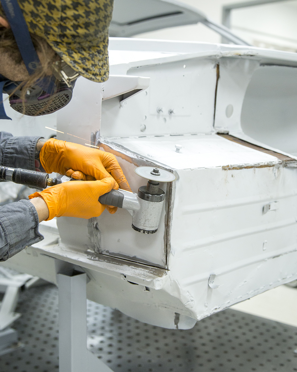
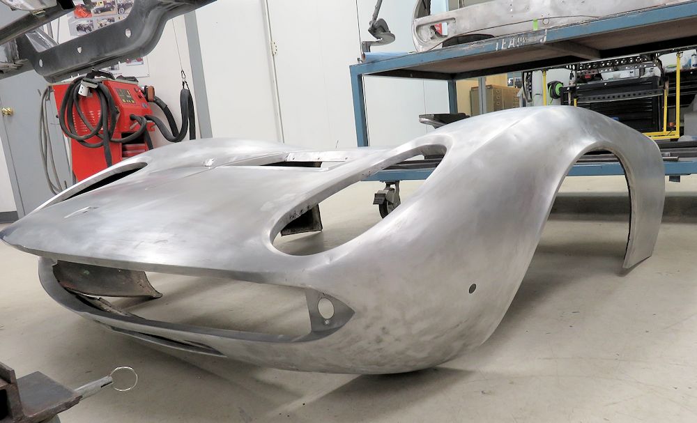
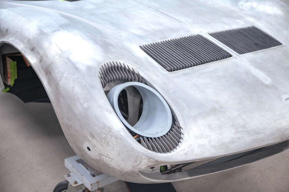
Update report - April 12, 2024
Bodywork complete
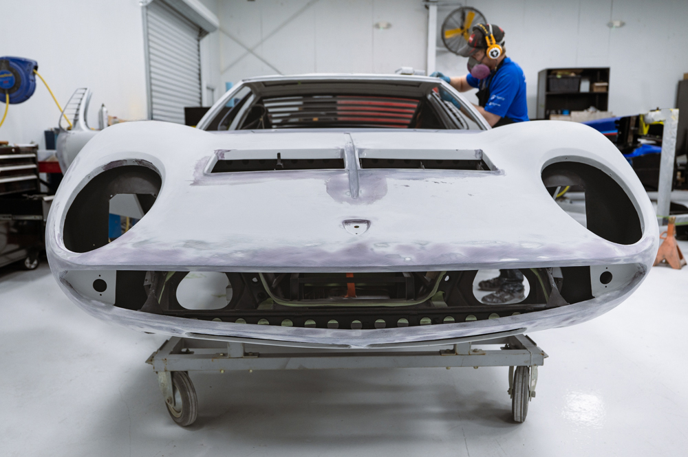
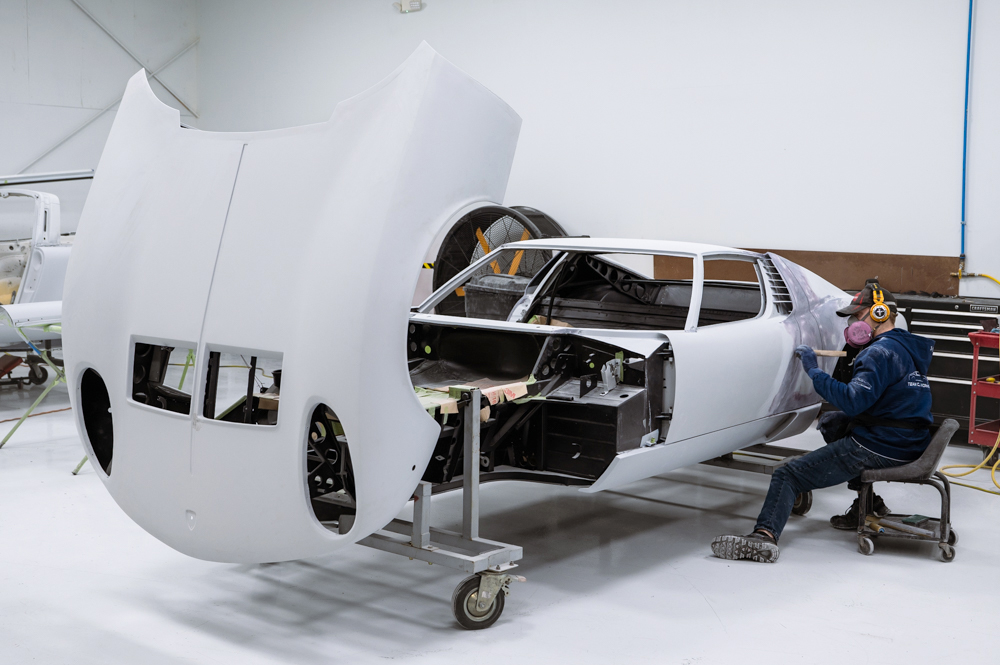
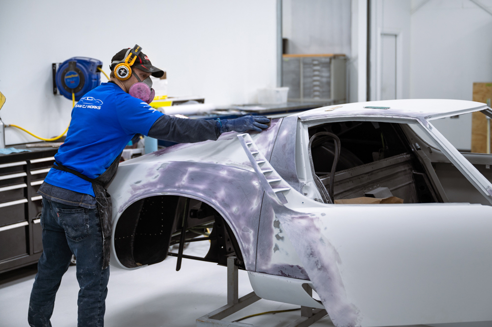
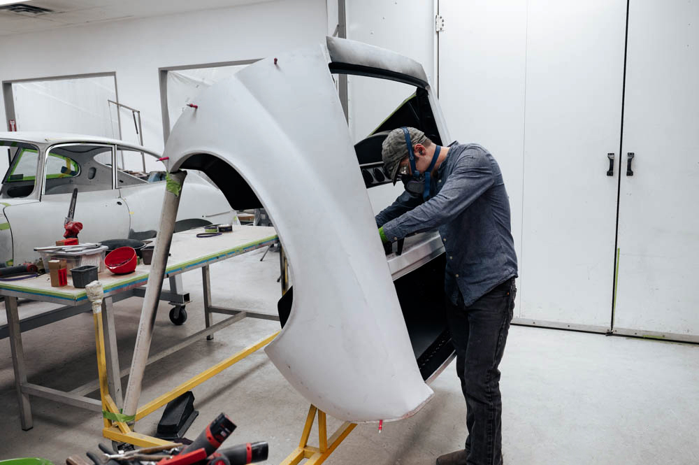
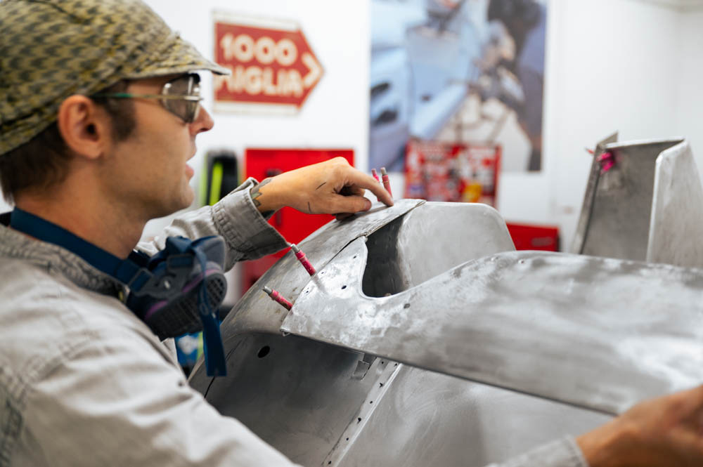
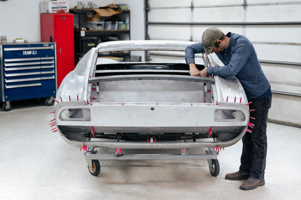
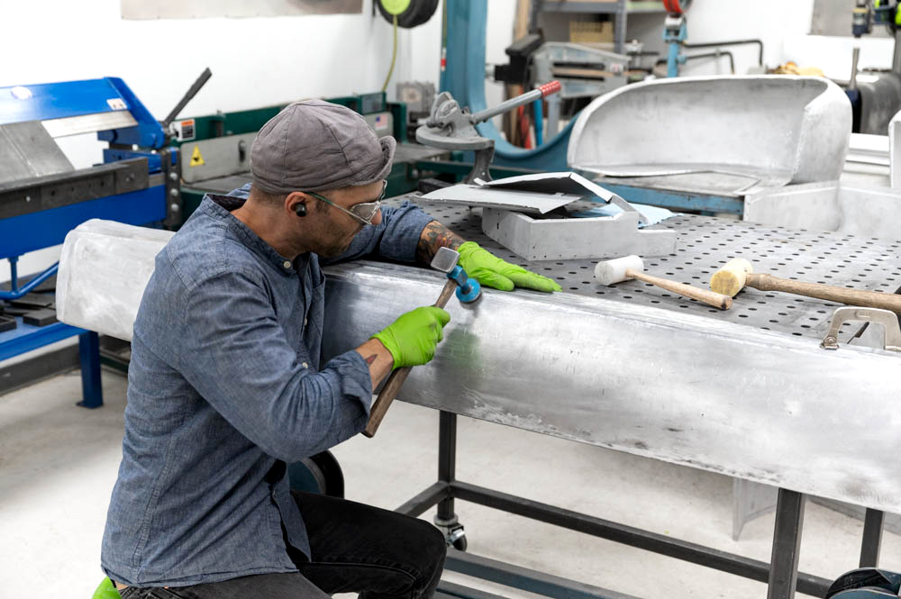
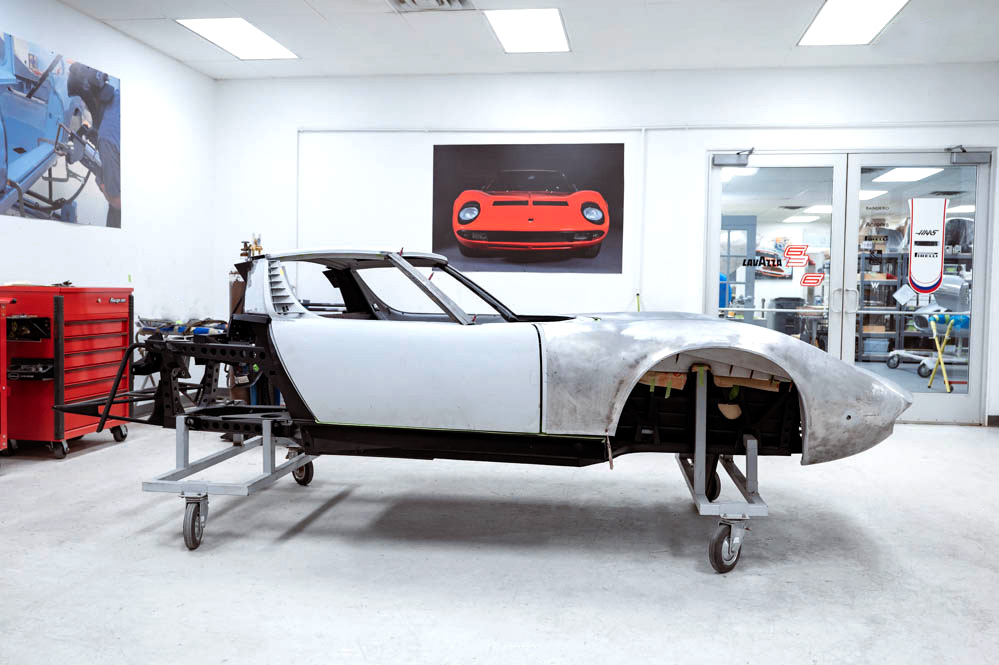
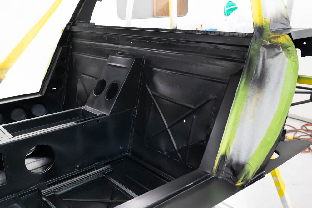
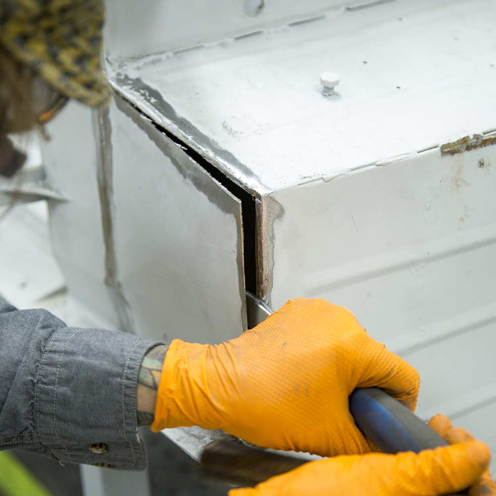
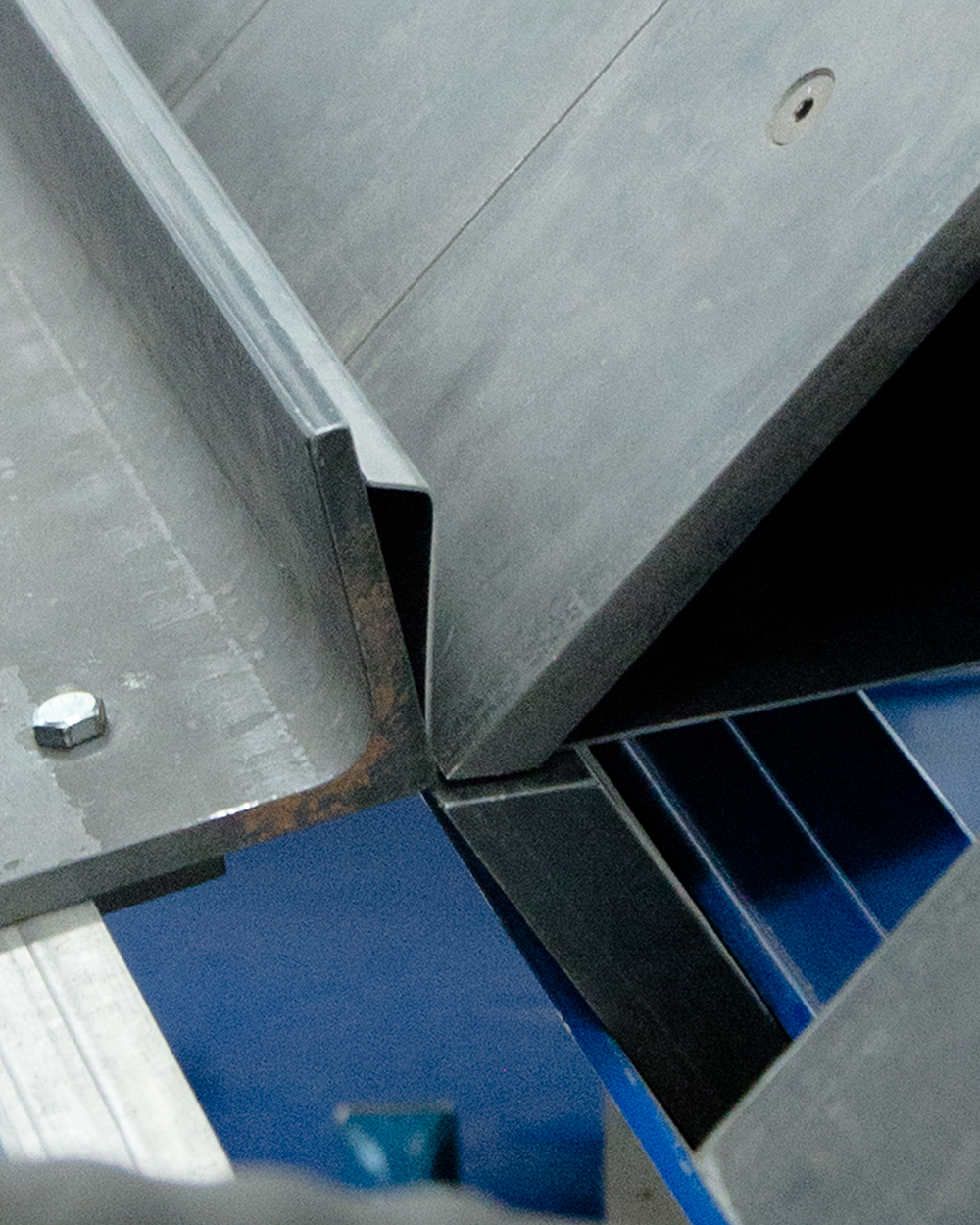
Update report - February 12, 2024
Edge and gap work
continues
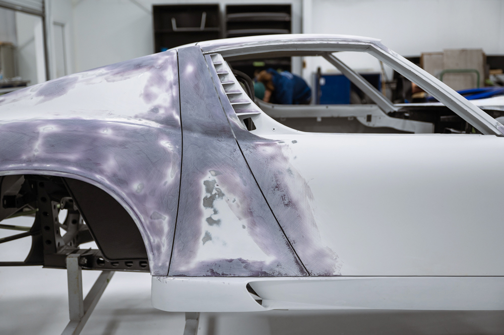
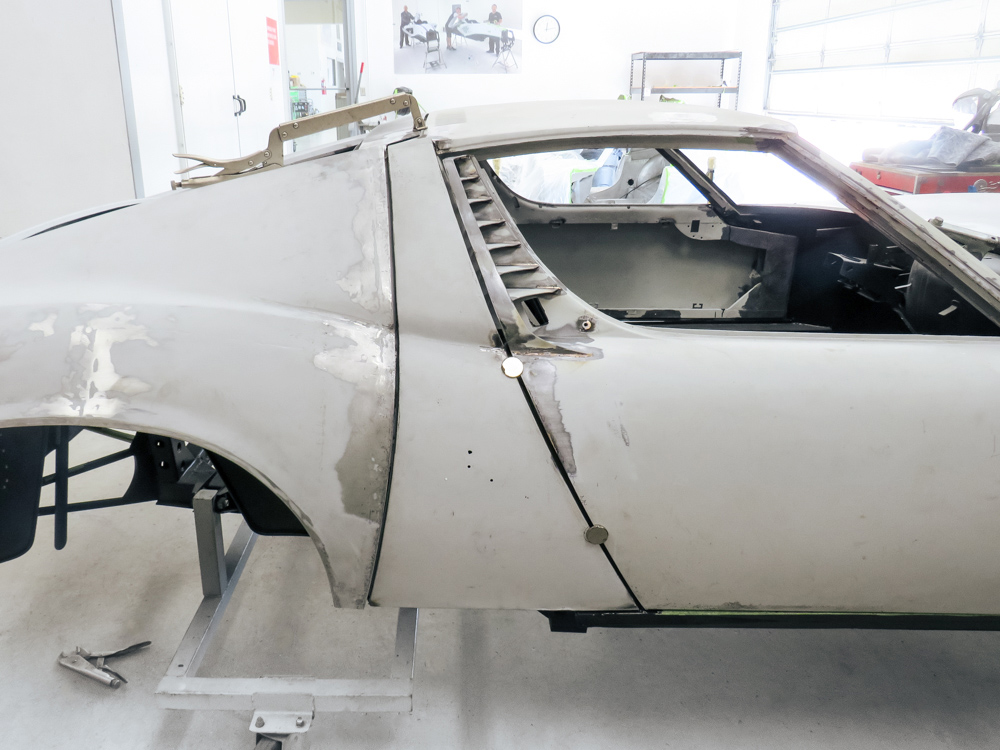
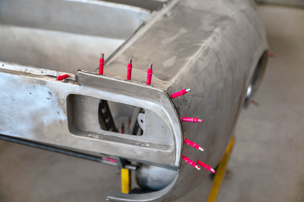
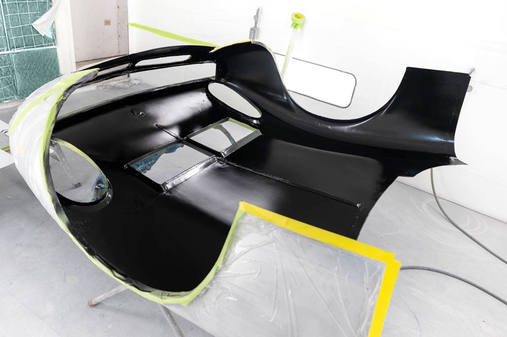
Update report - January 4, 2024
Panel gap work.
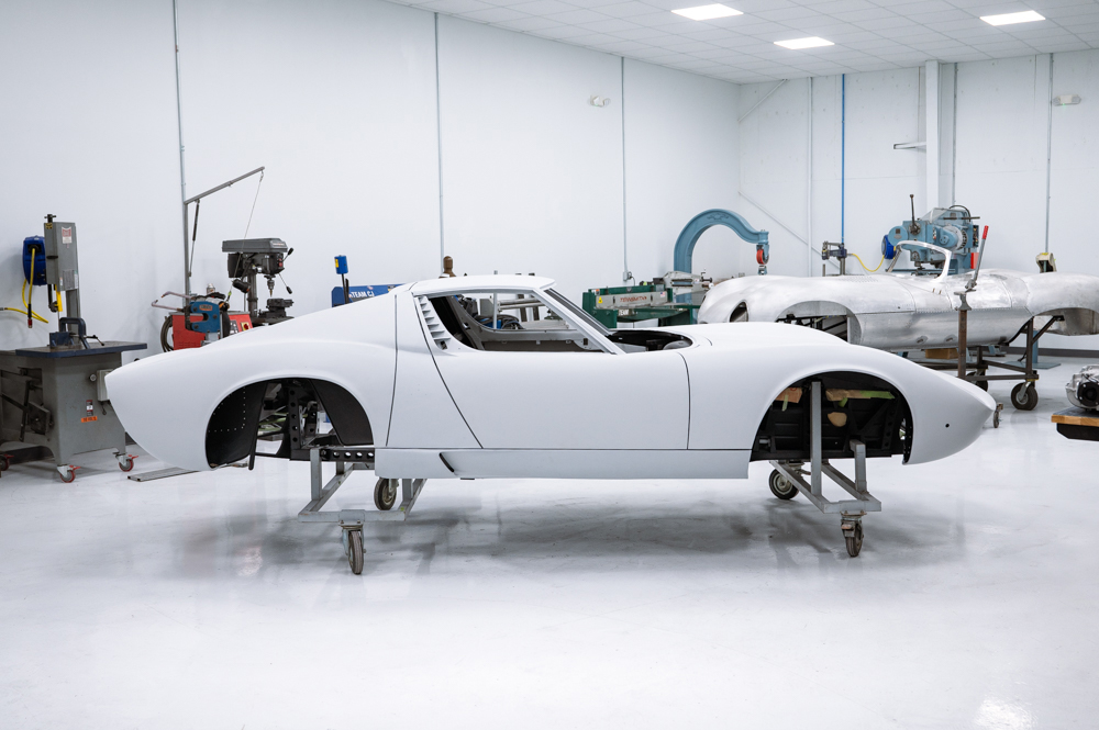
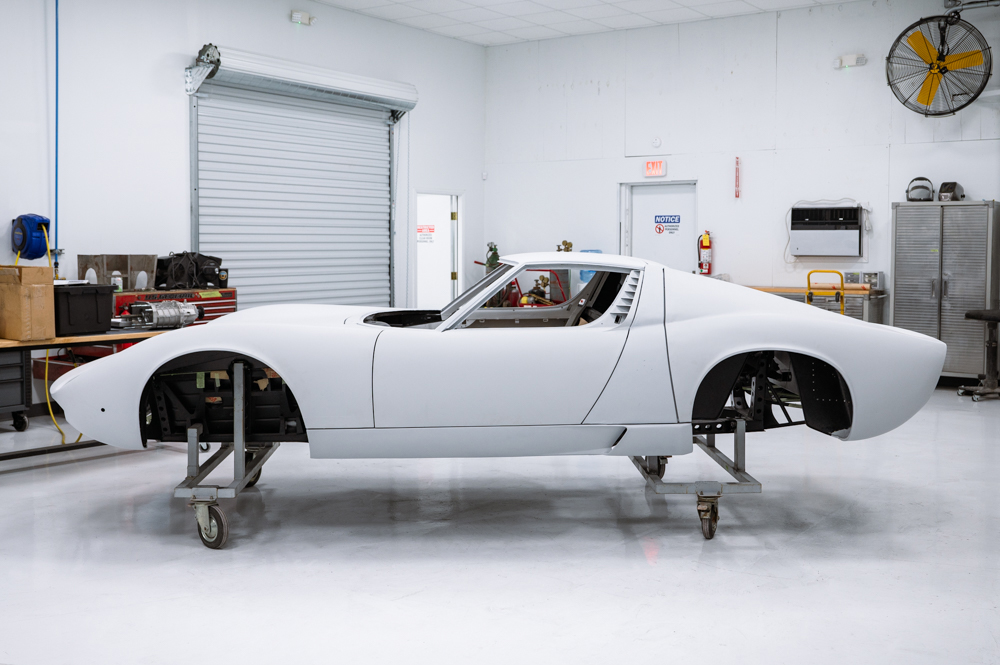
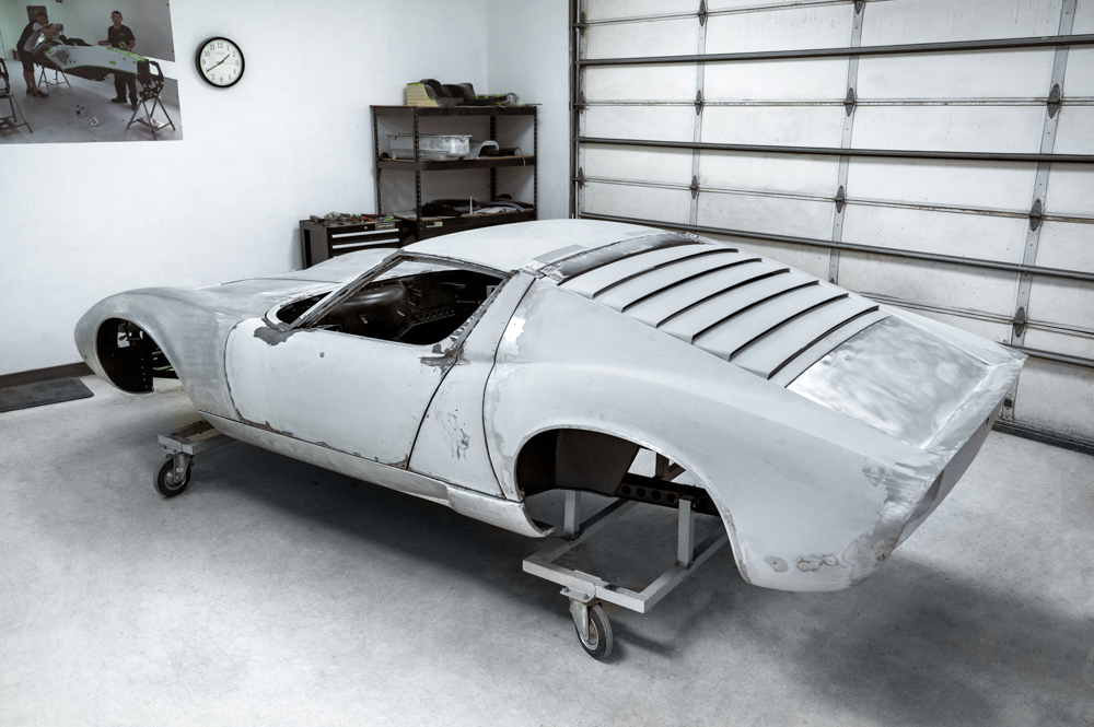
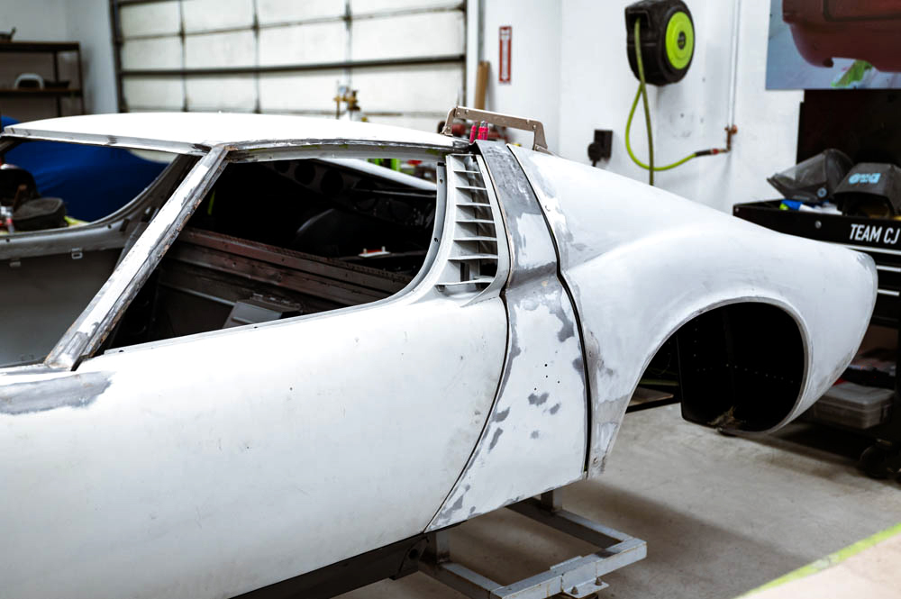
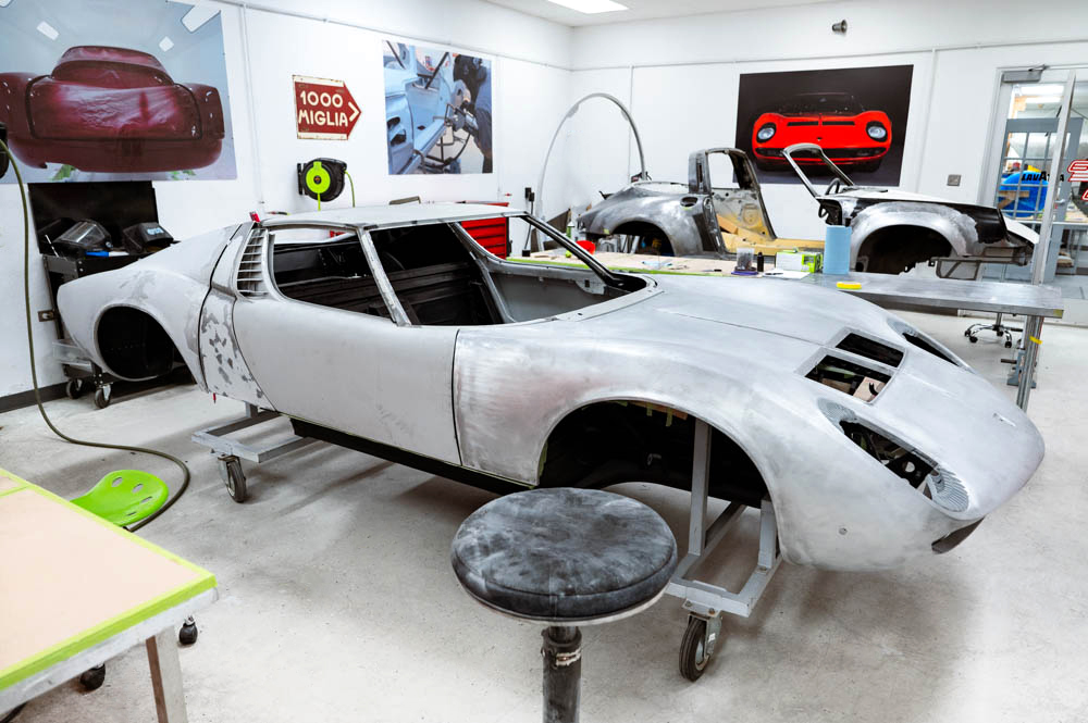
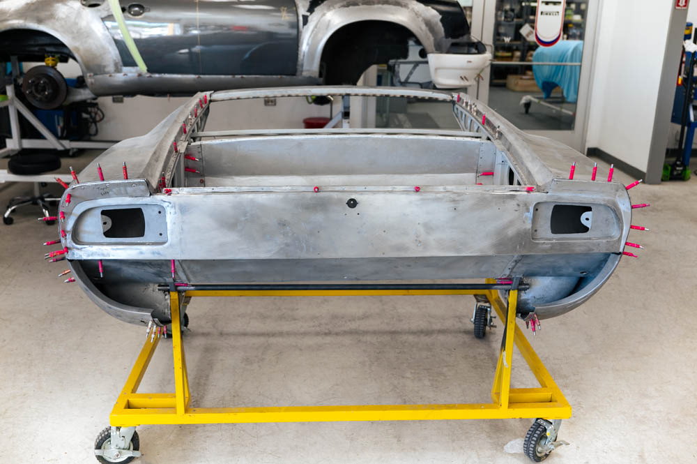
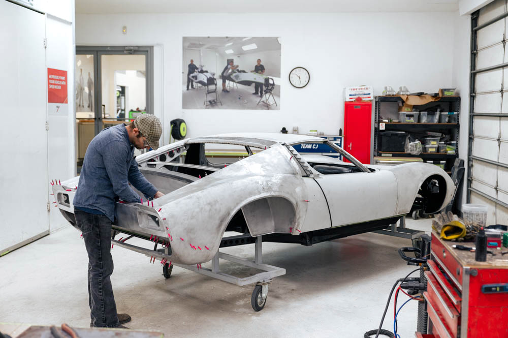
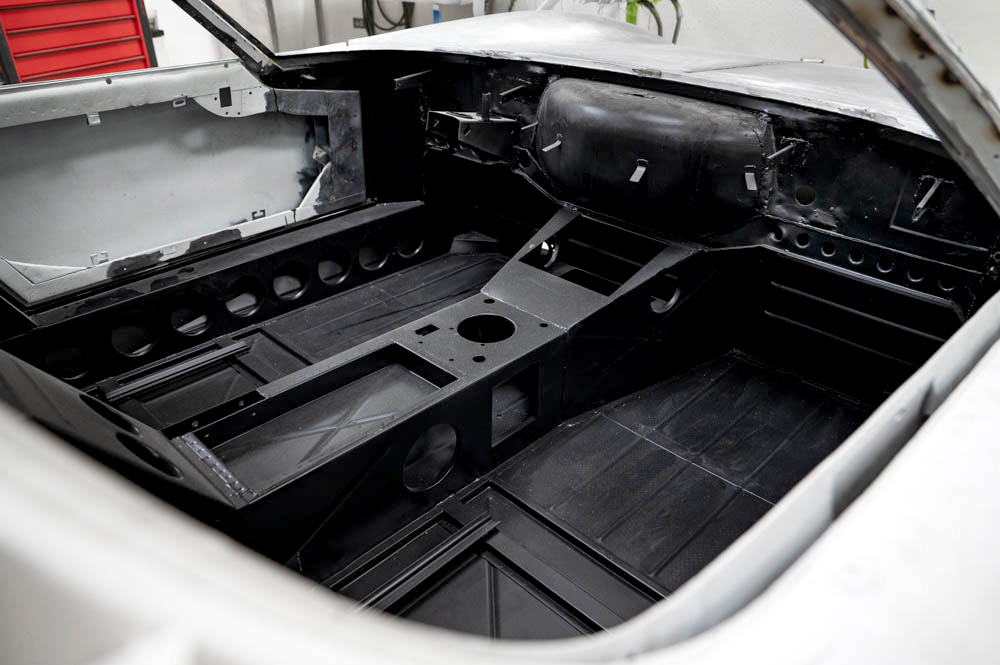
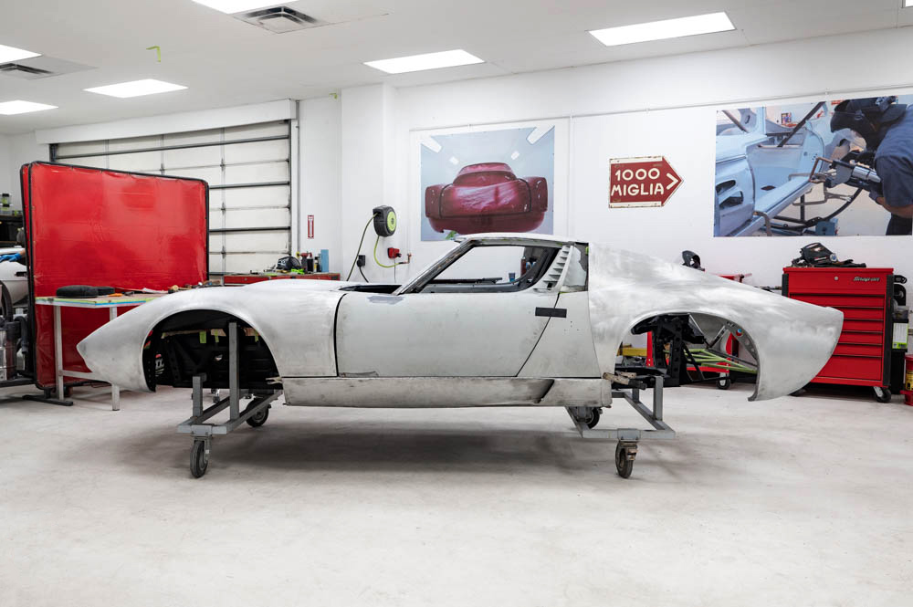
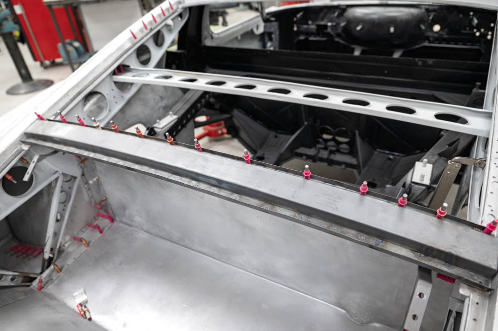
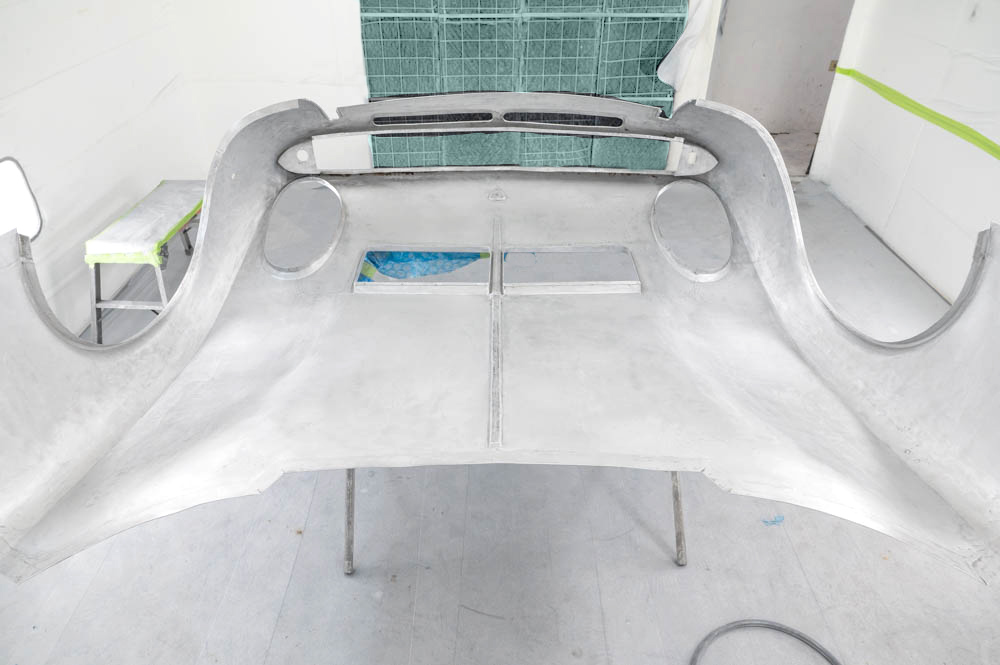
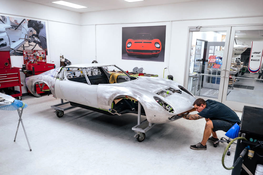
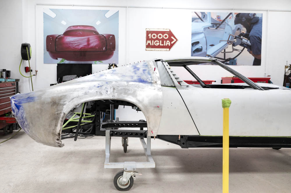
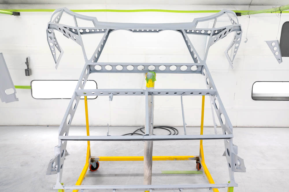
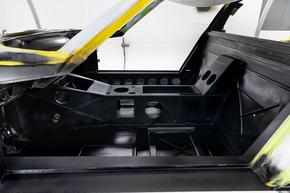
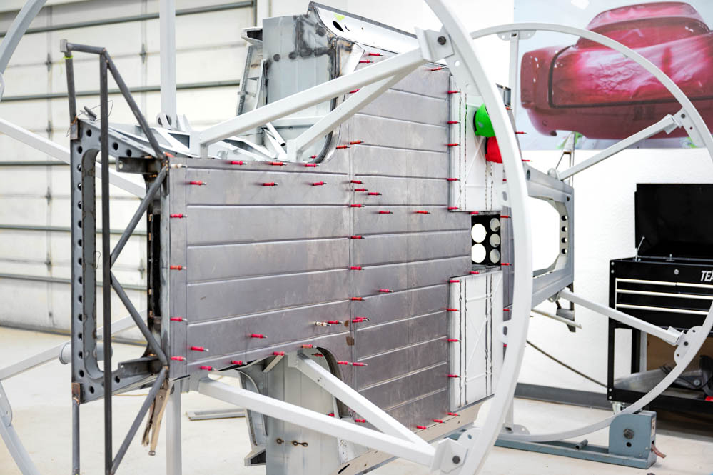
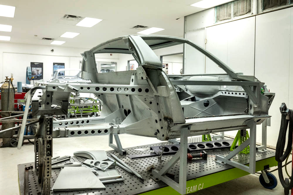
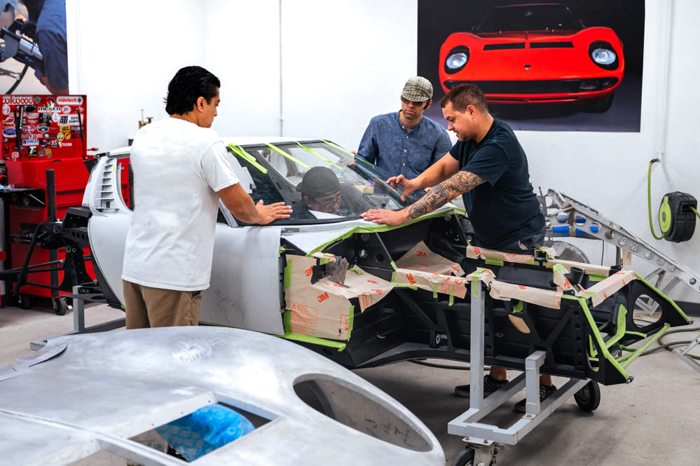
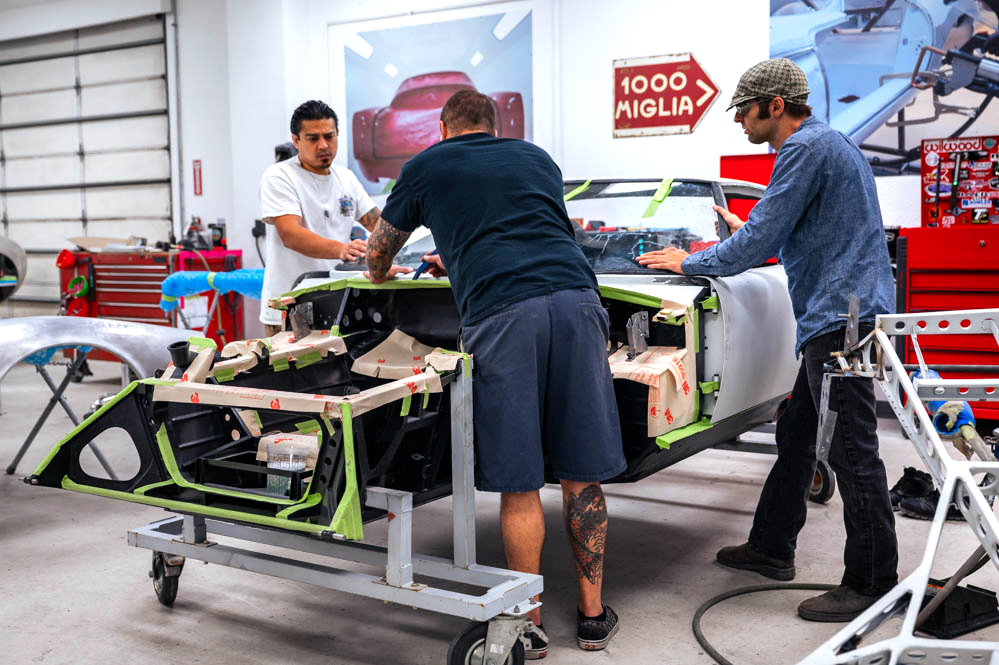
Update report - November 20, 2023
Ready for
bodywork
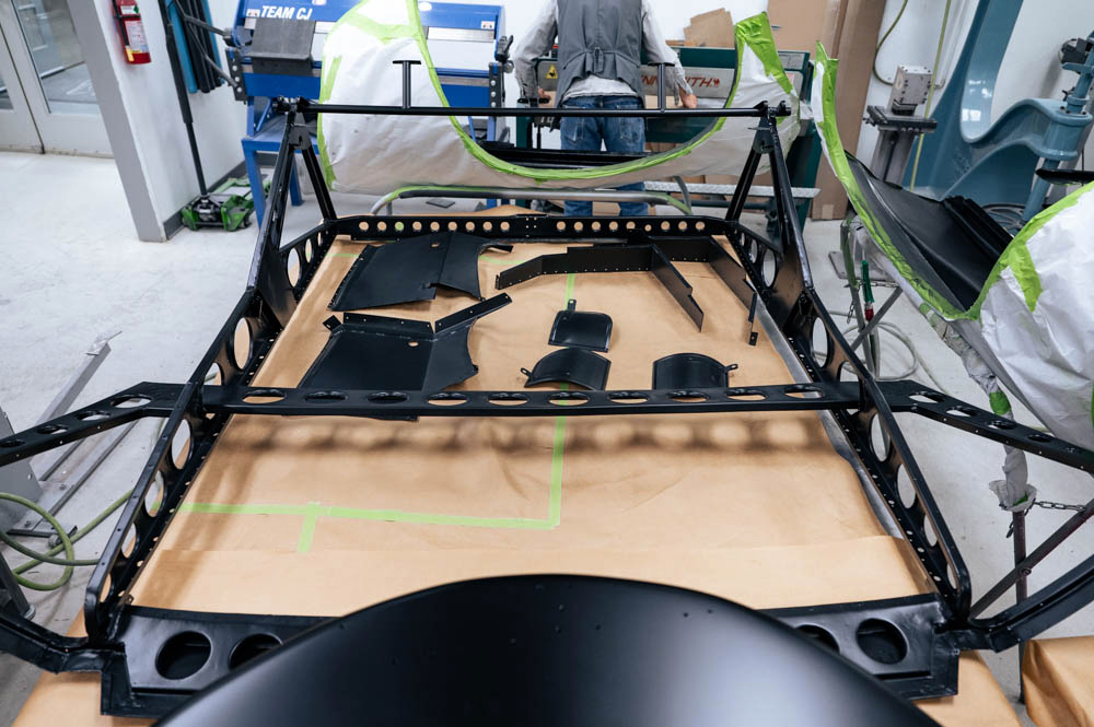
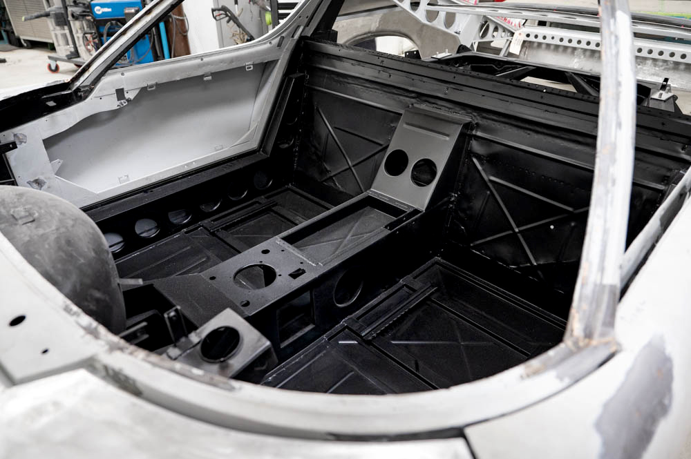
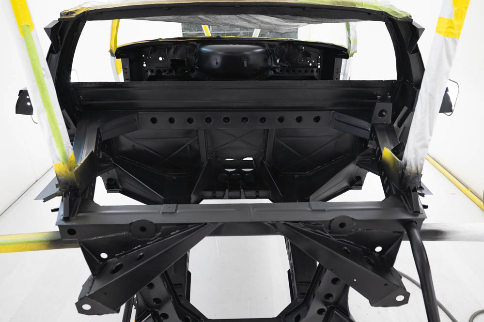
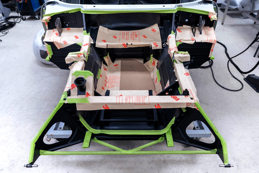
Update report - November 8, 2023
Front clip, rear
clip and doors sealed
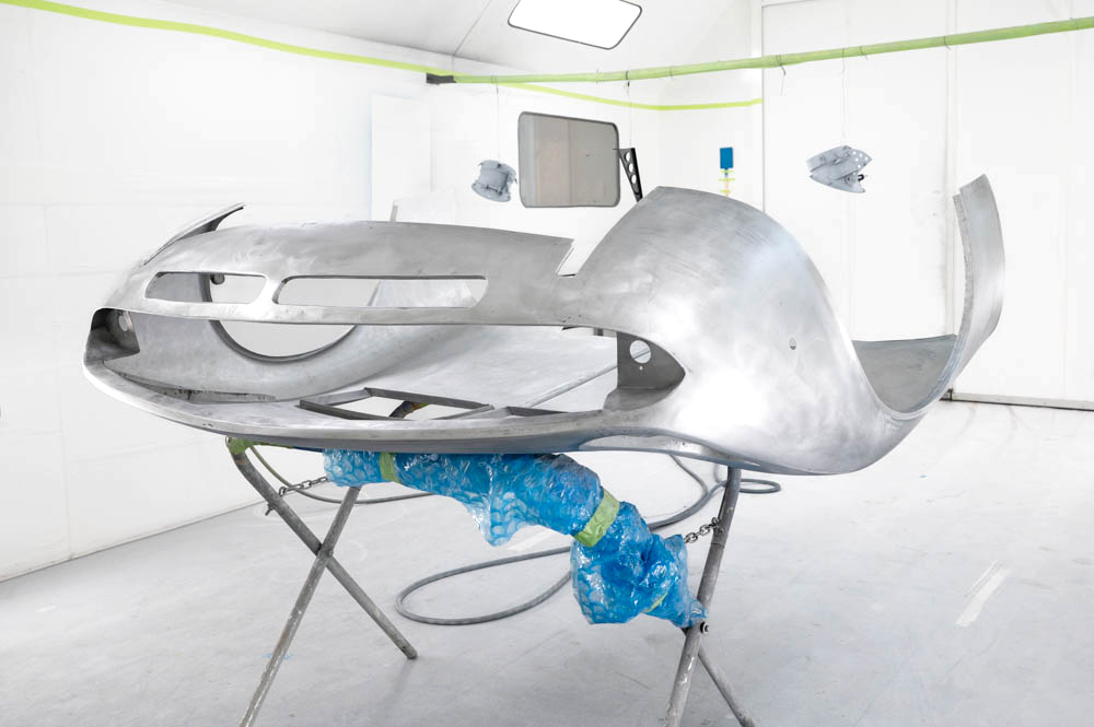
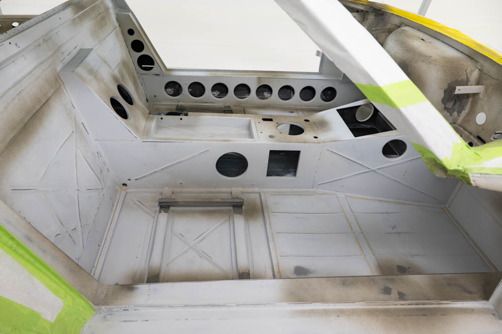
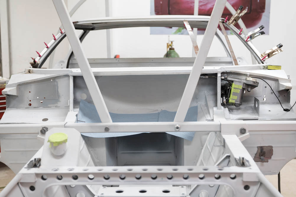
Update report - November 2, 2023
Sealed and ready
for bodywork.
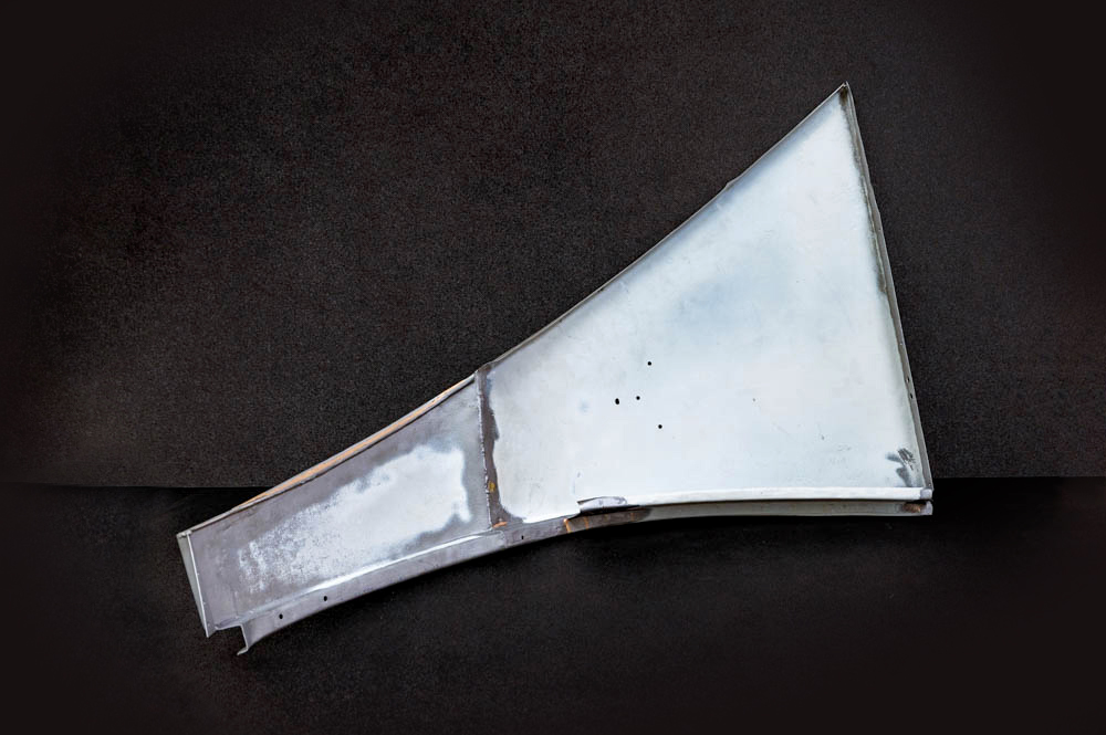
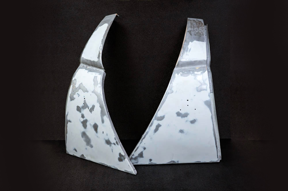
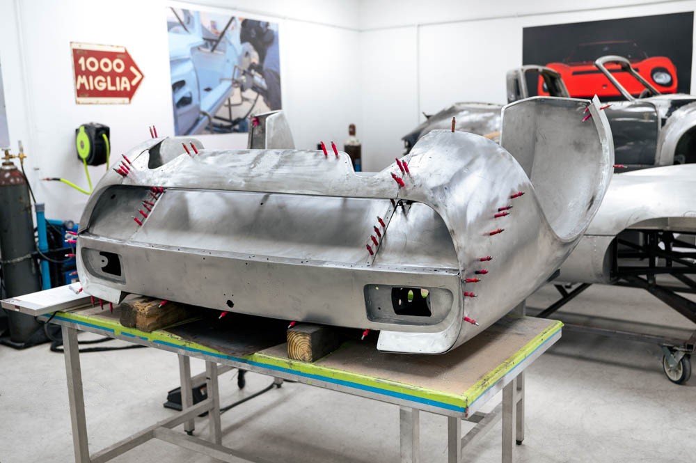
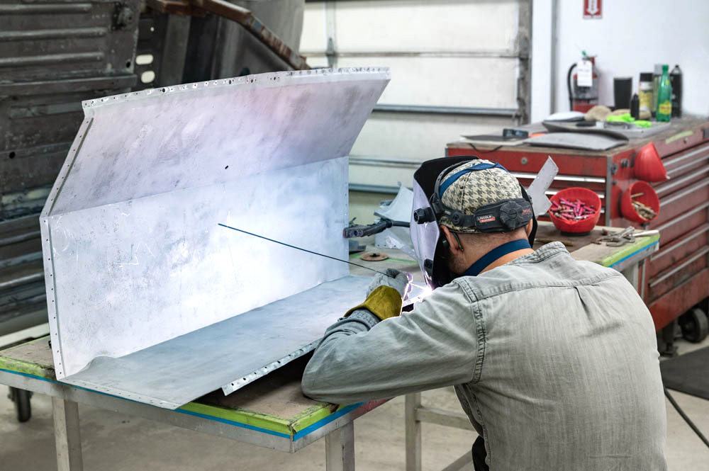
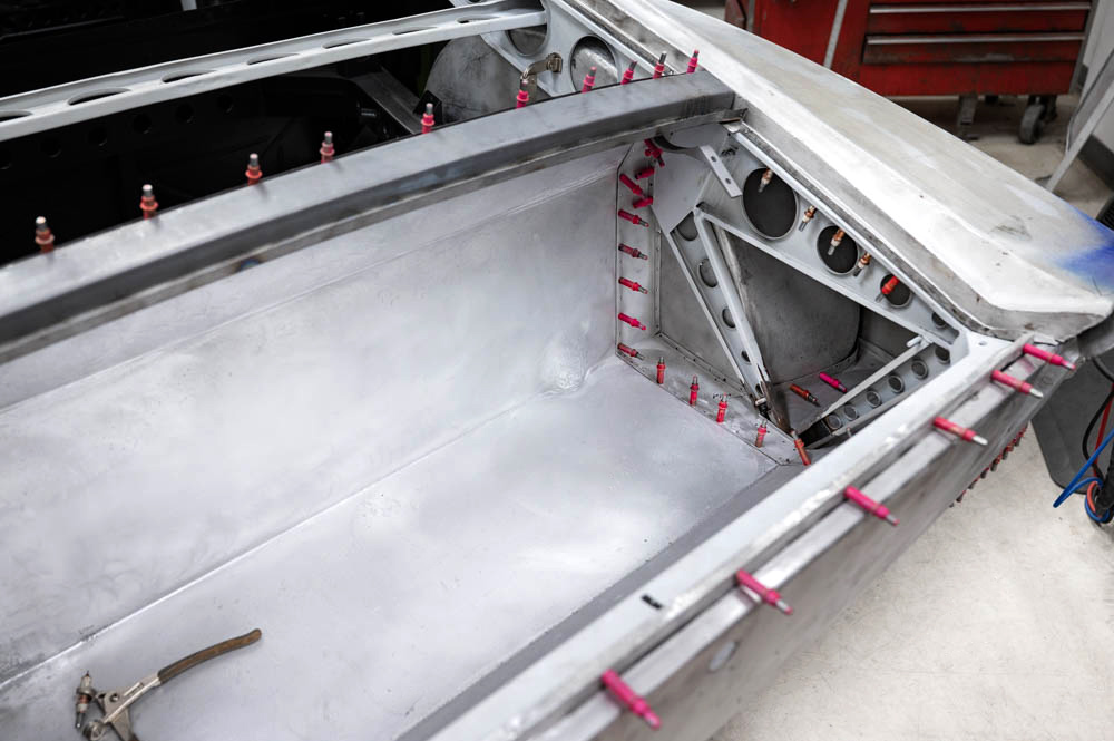
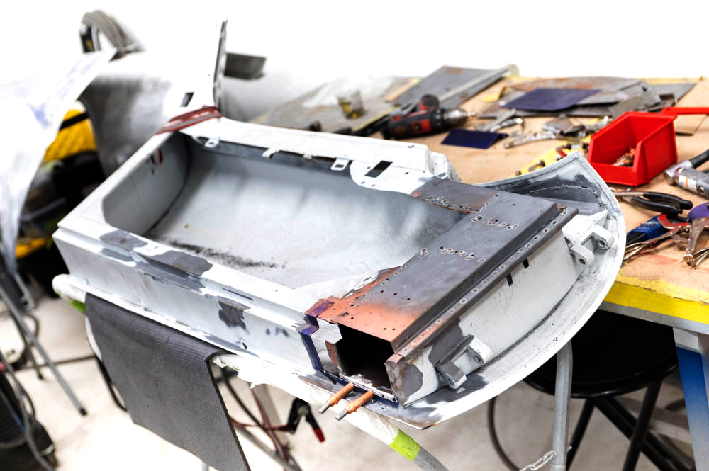
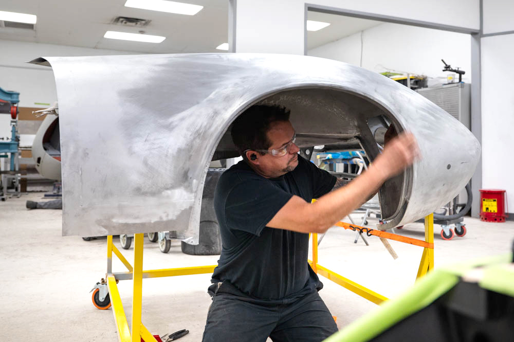
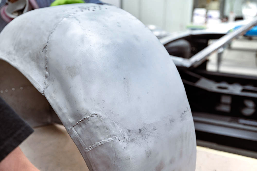
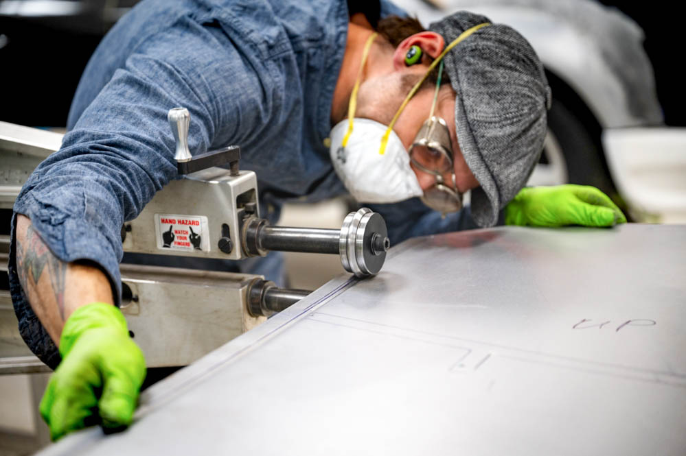
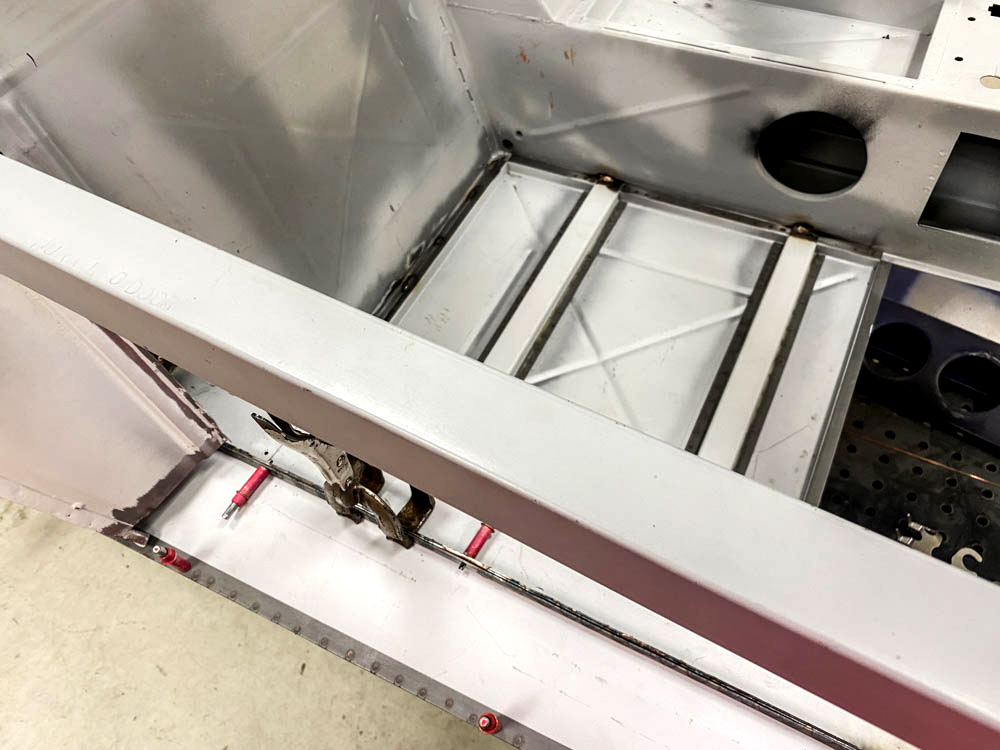
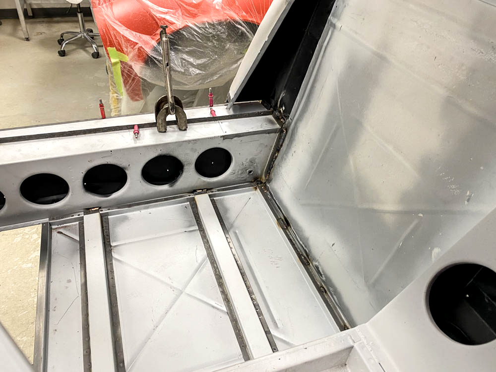
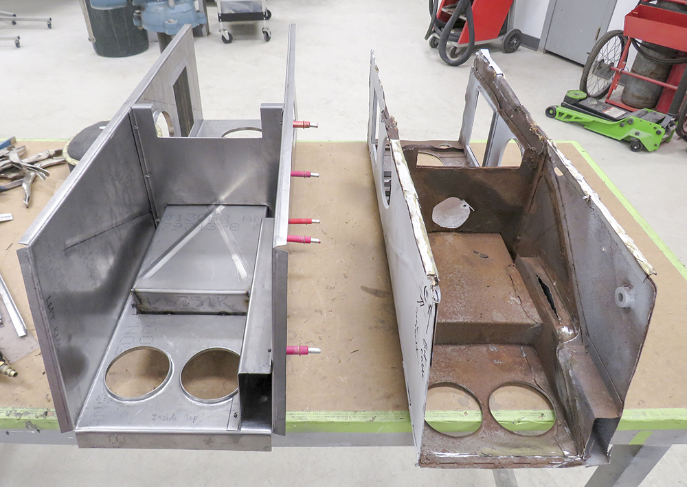
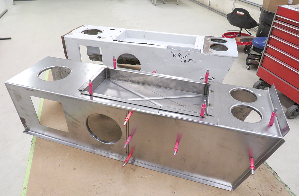
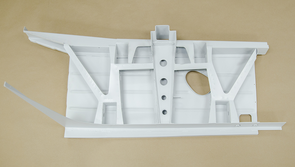
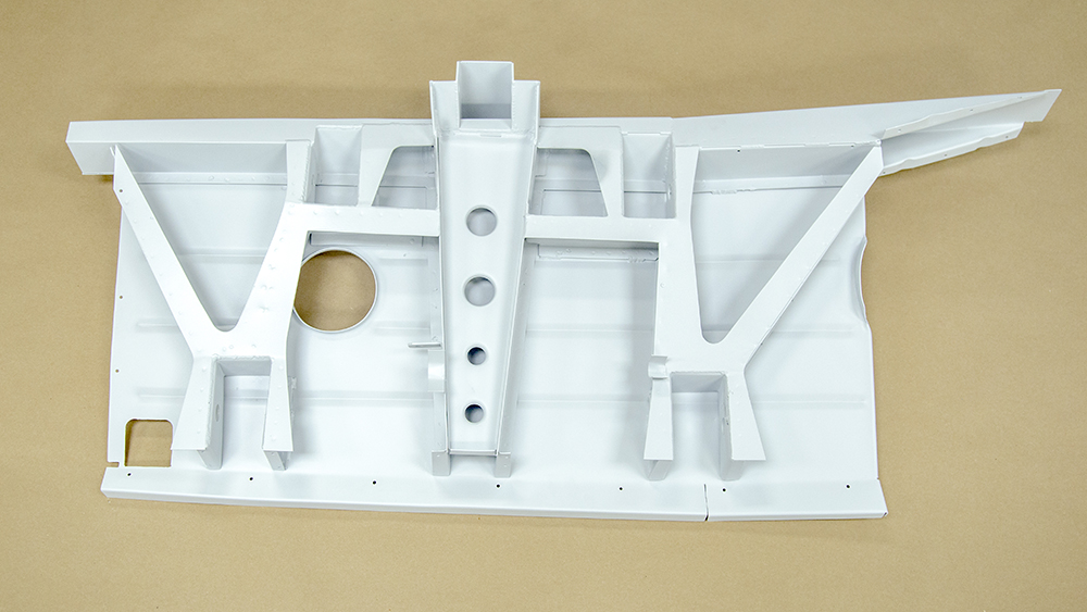
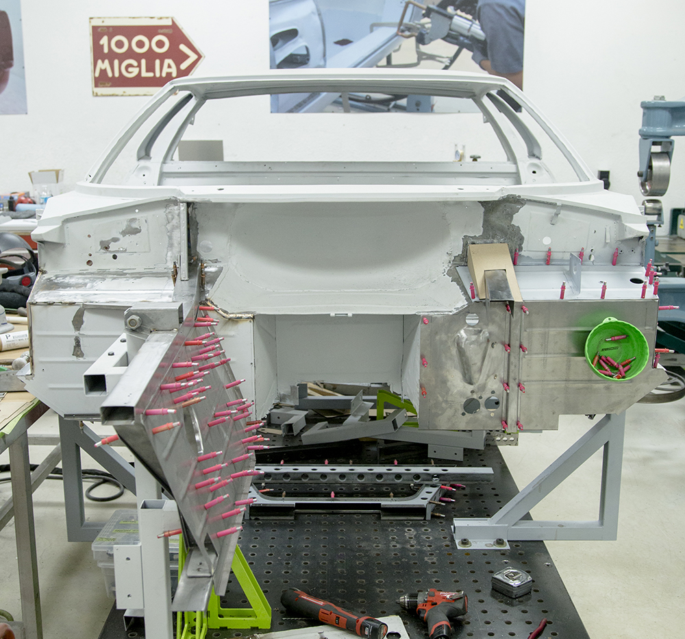
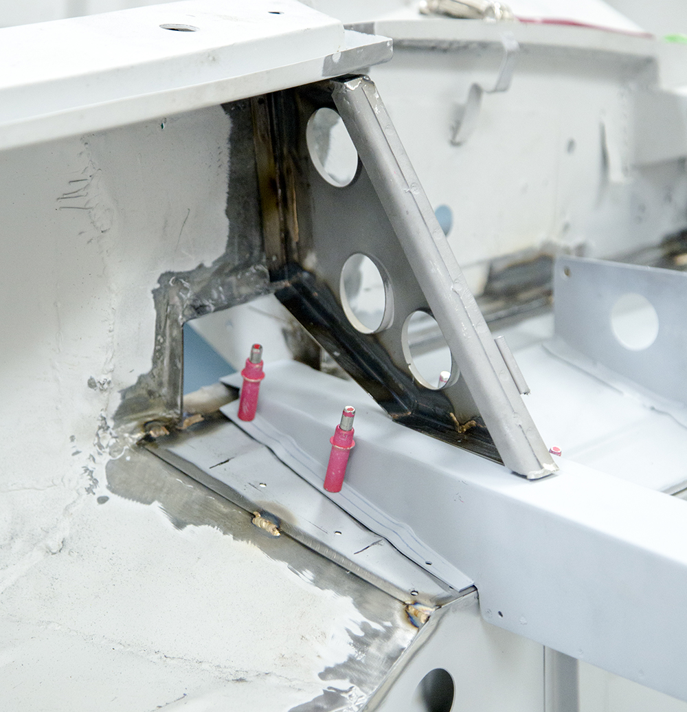
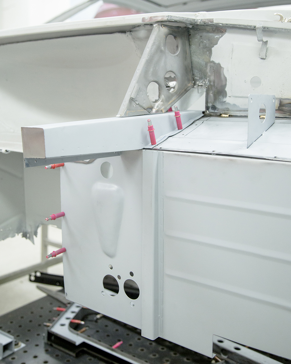
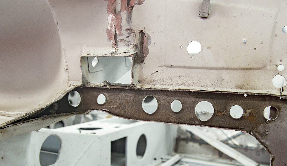
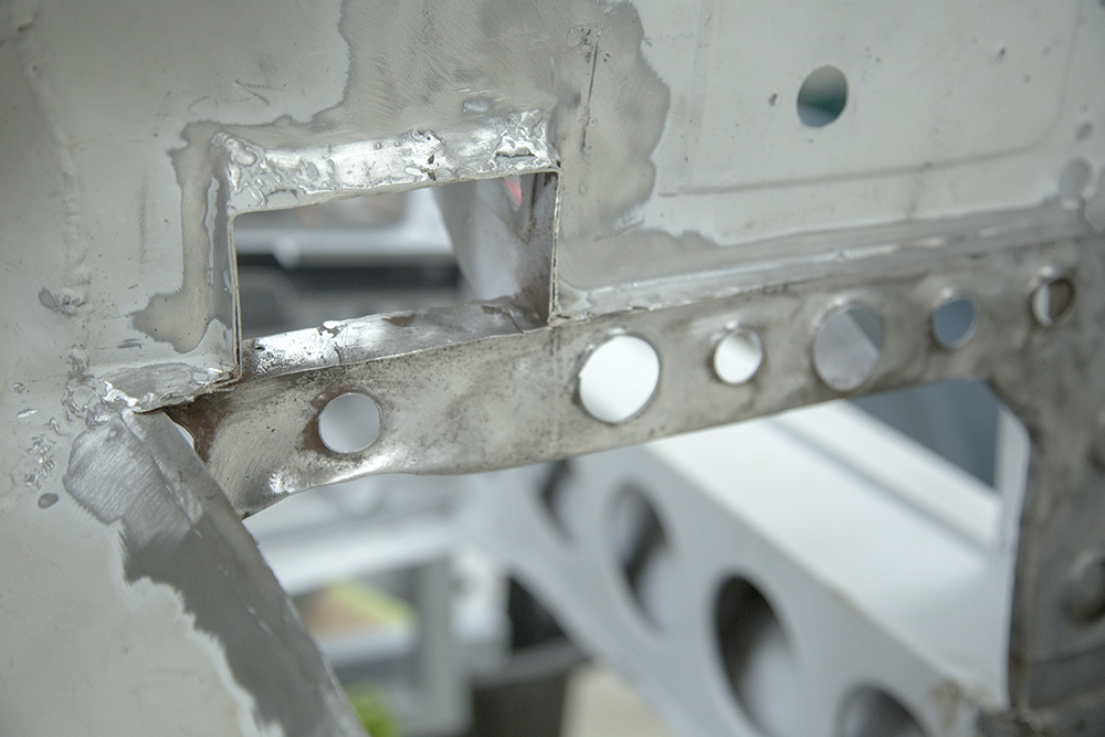
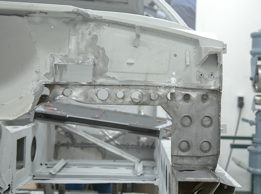
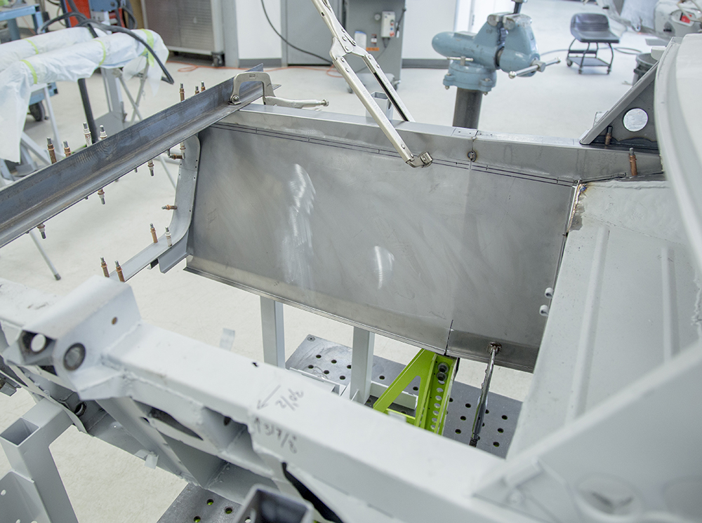
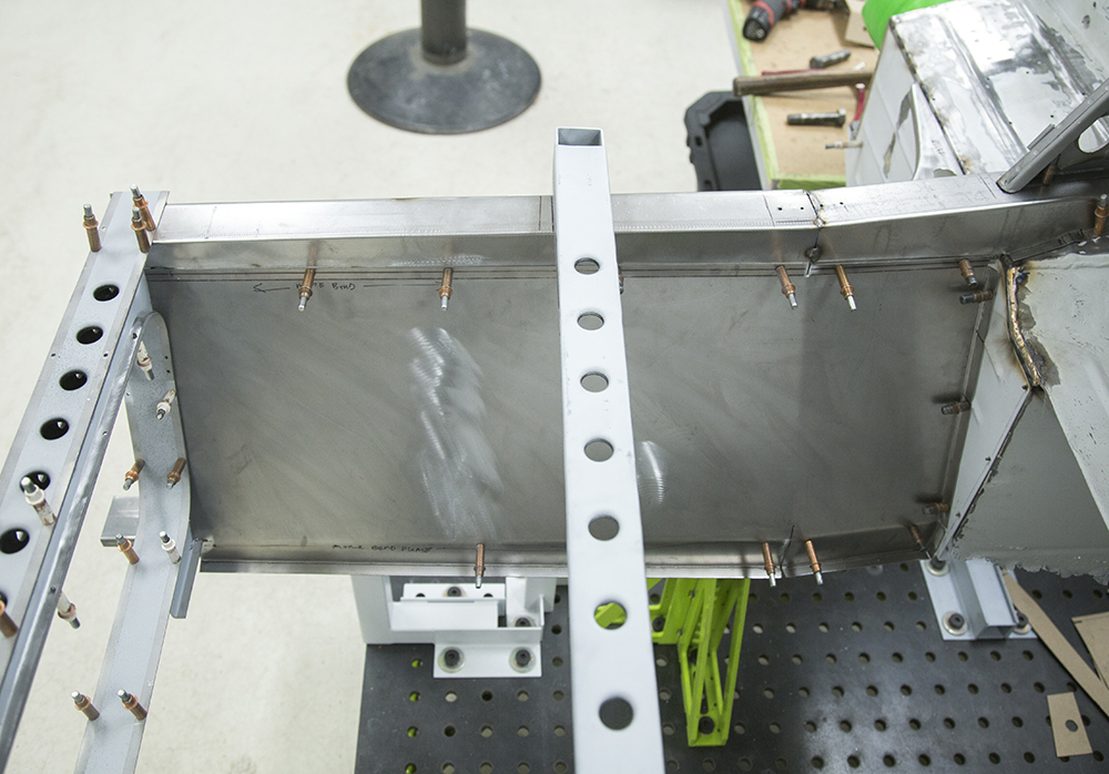
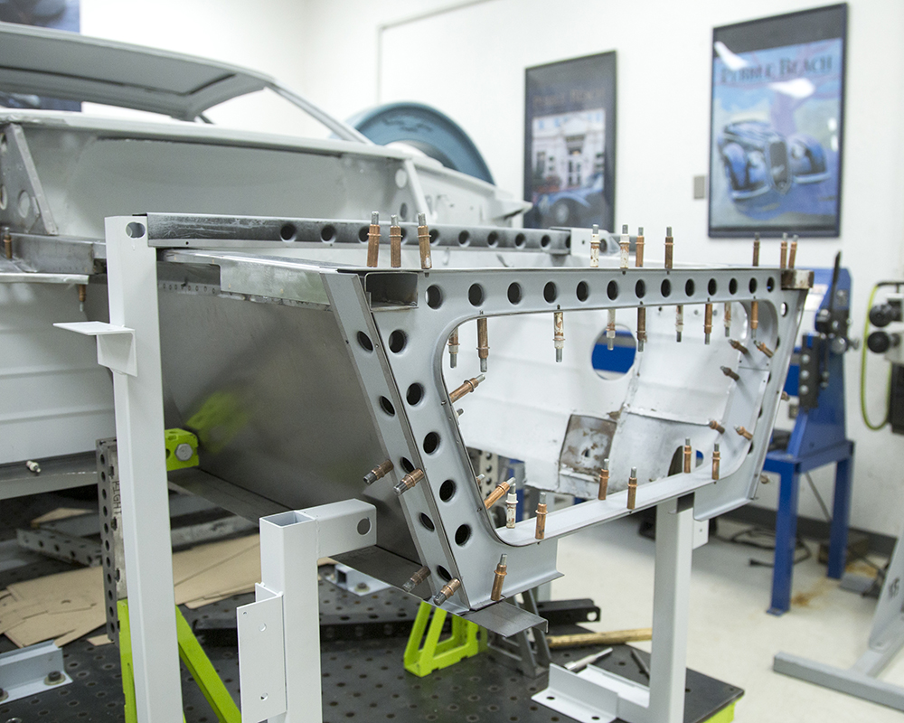
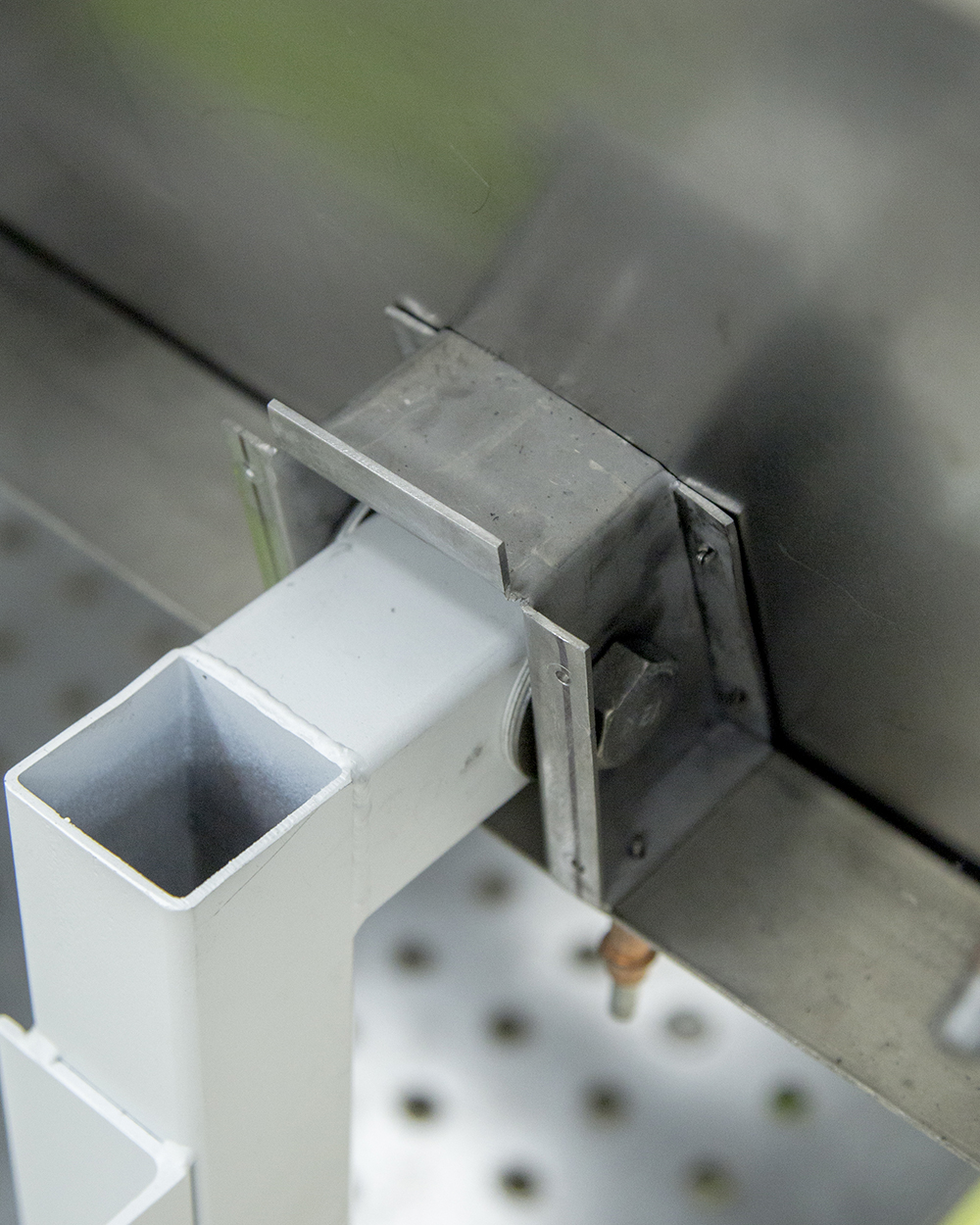
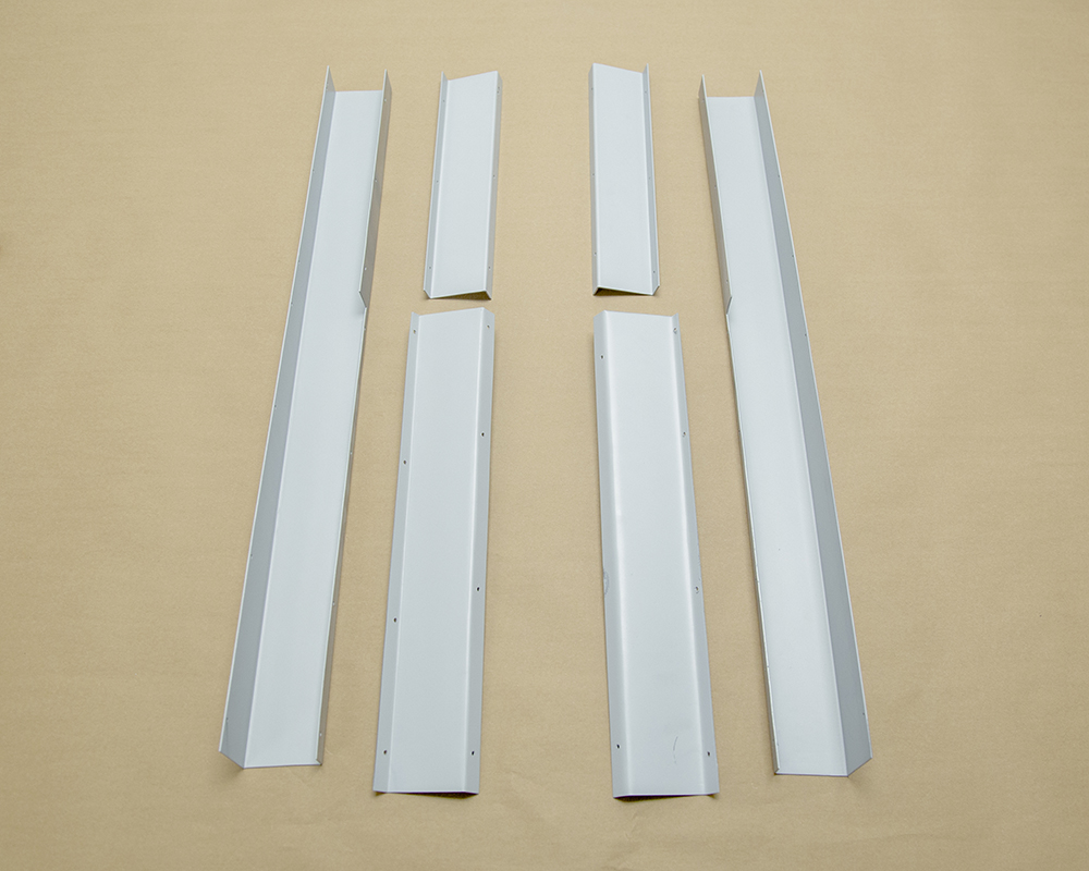
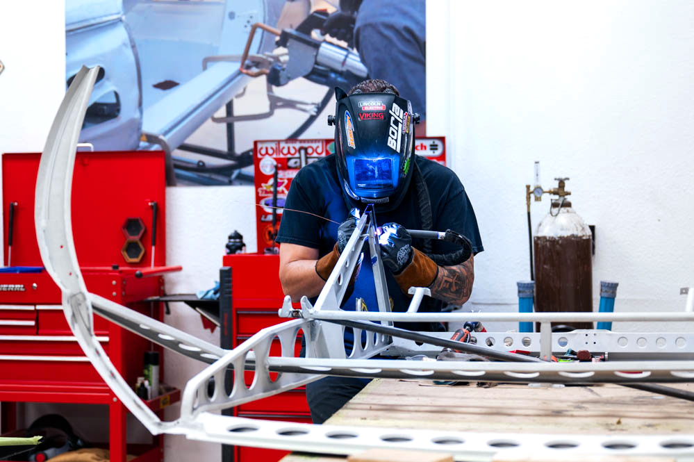
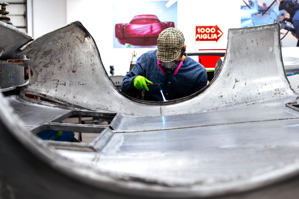
Update report - April 11, 2023
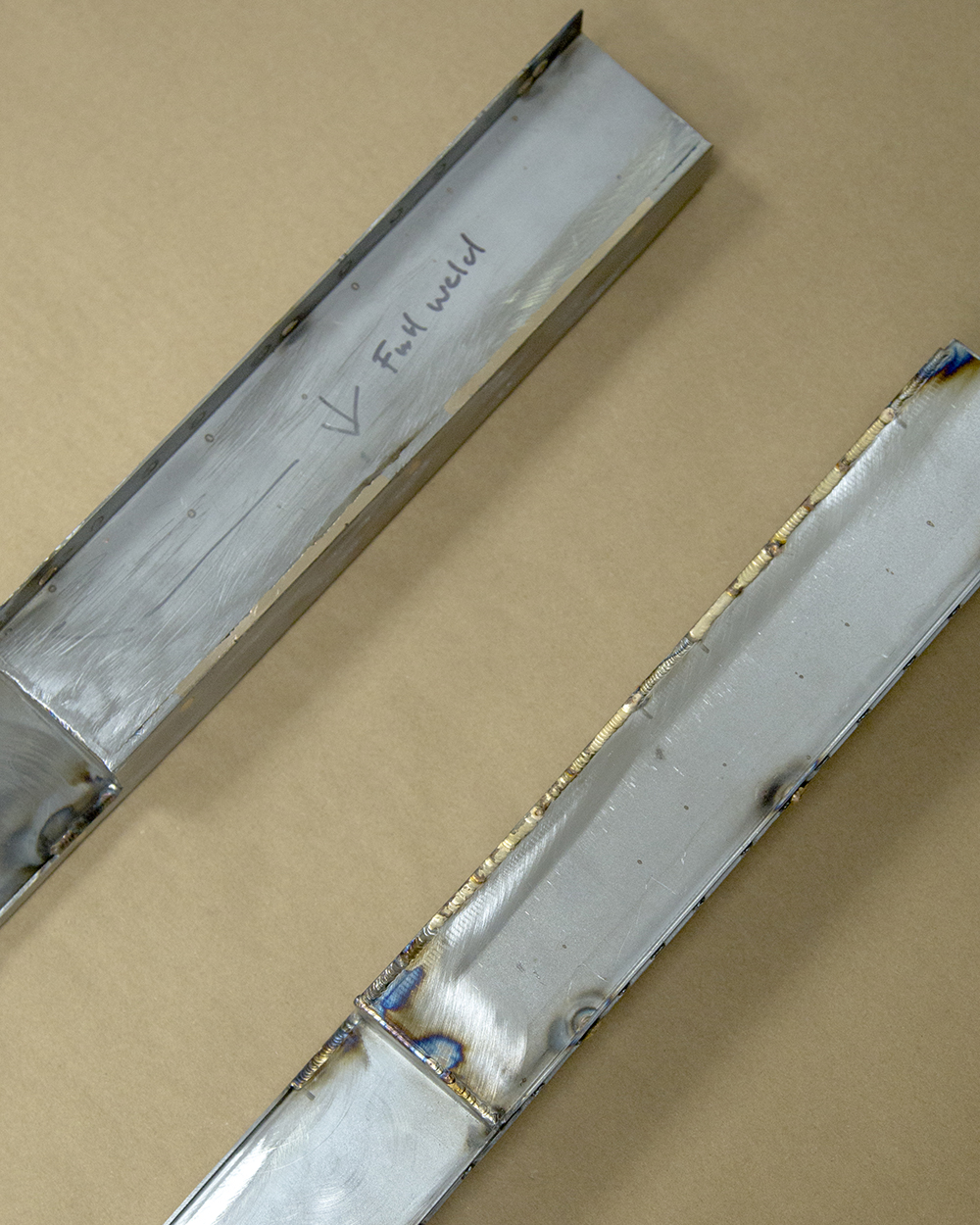
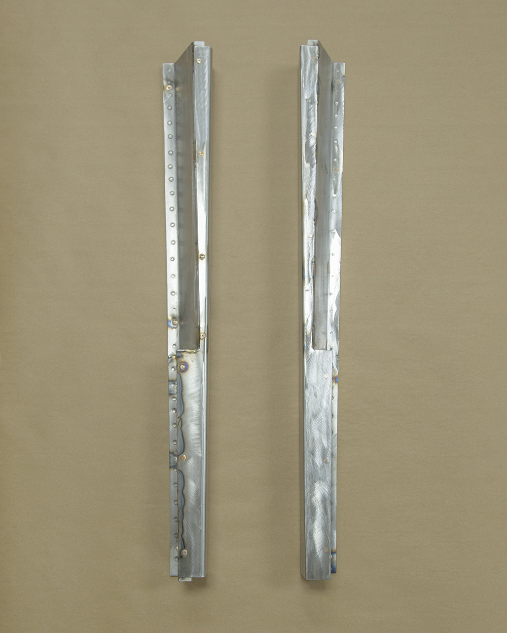
Sheet metal
work complete, ready for sealing and body work.
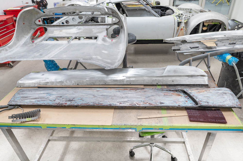
Update report - April 7, 2023
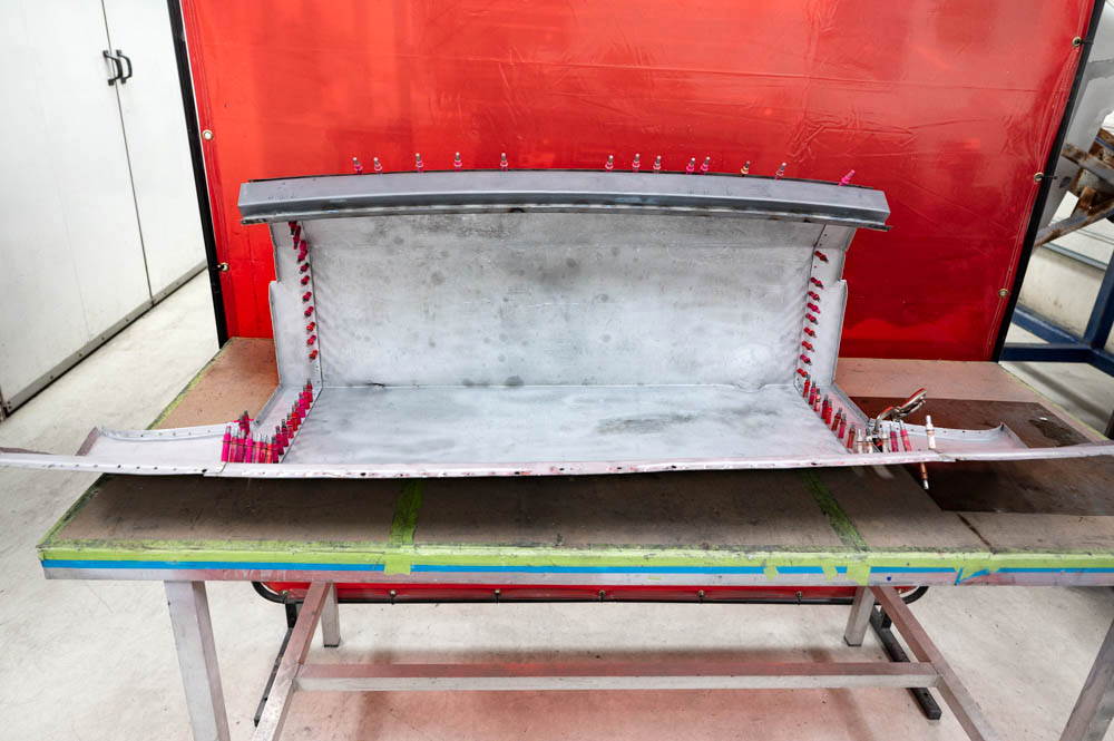
Boot lid
reskinned
Update report - March 27, 2023
Update report - February 8, 2023
Update report - January 13, 2023
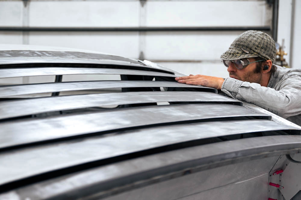
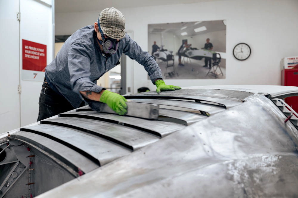
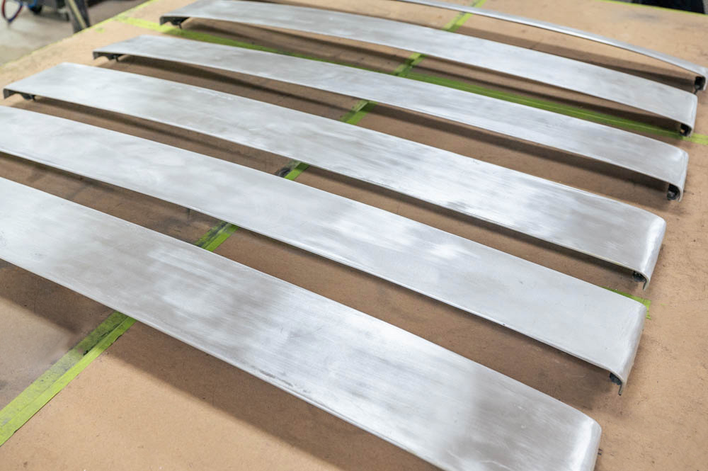
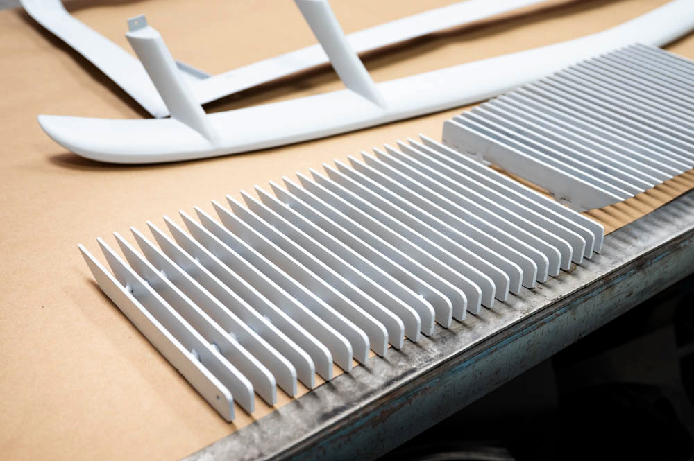
Update report - November 15,
2022
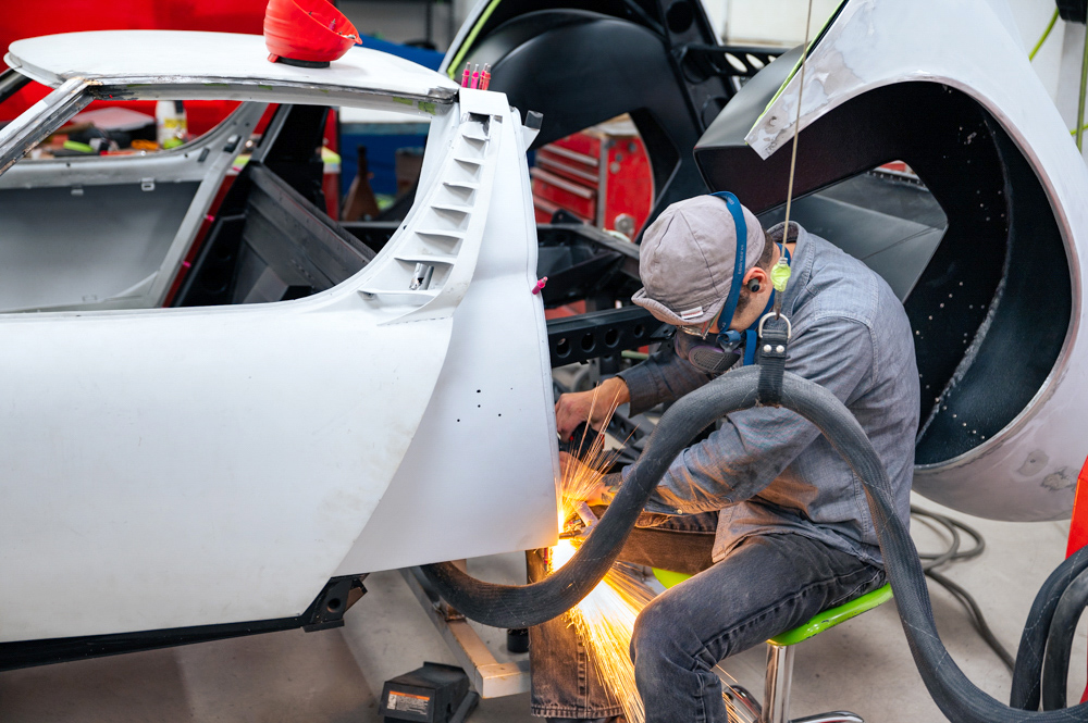
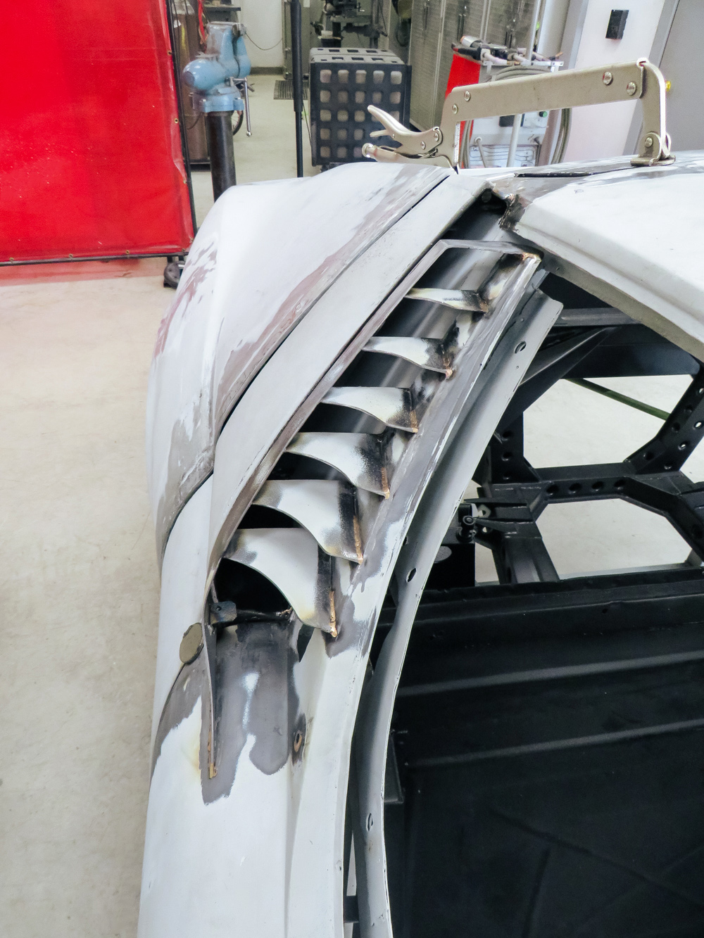
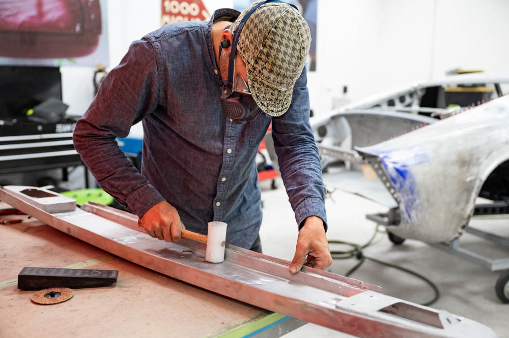
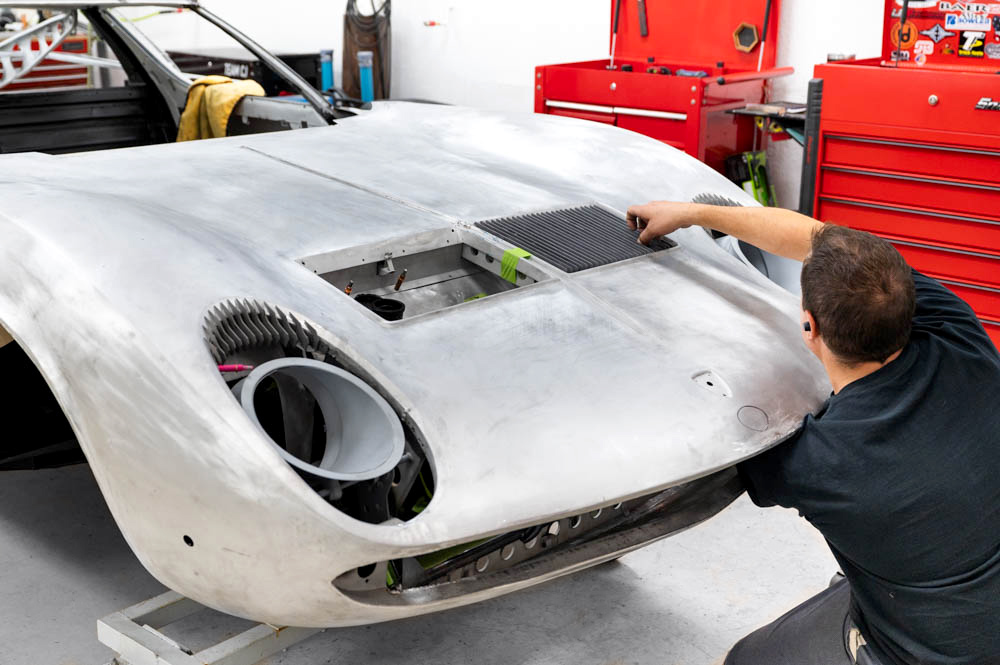
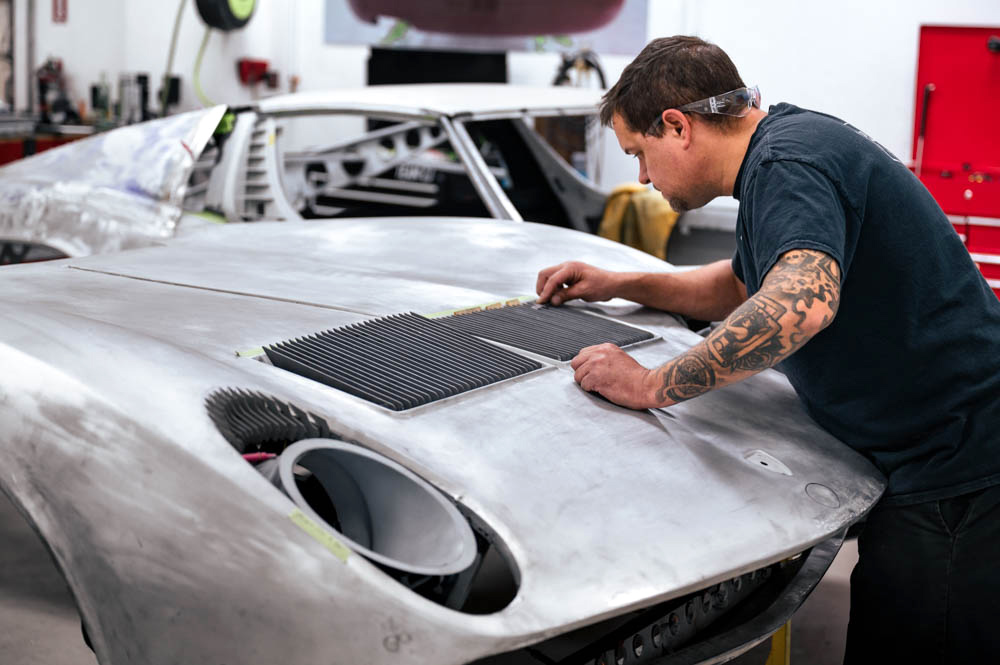
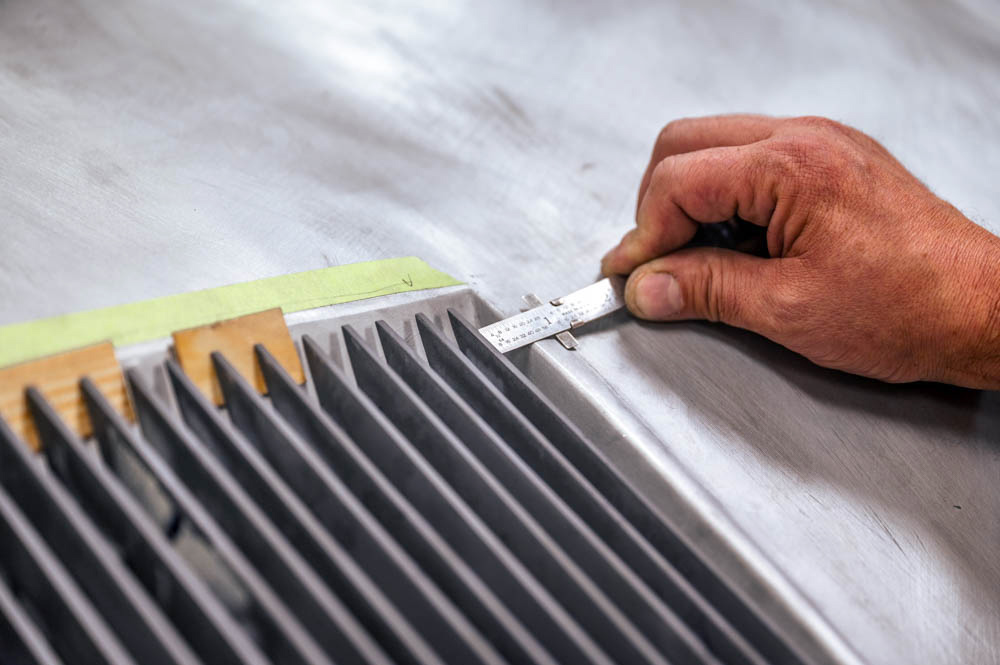
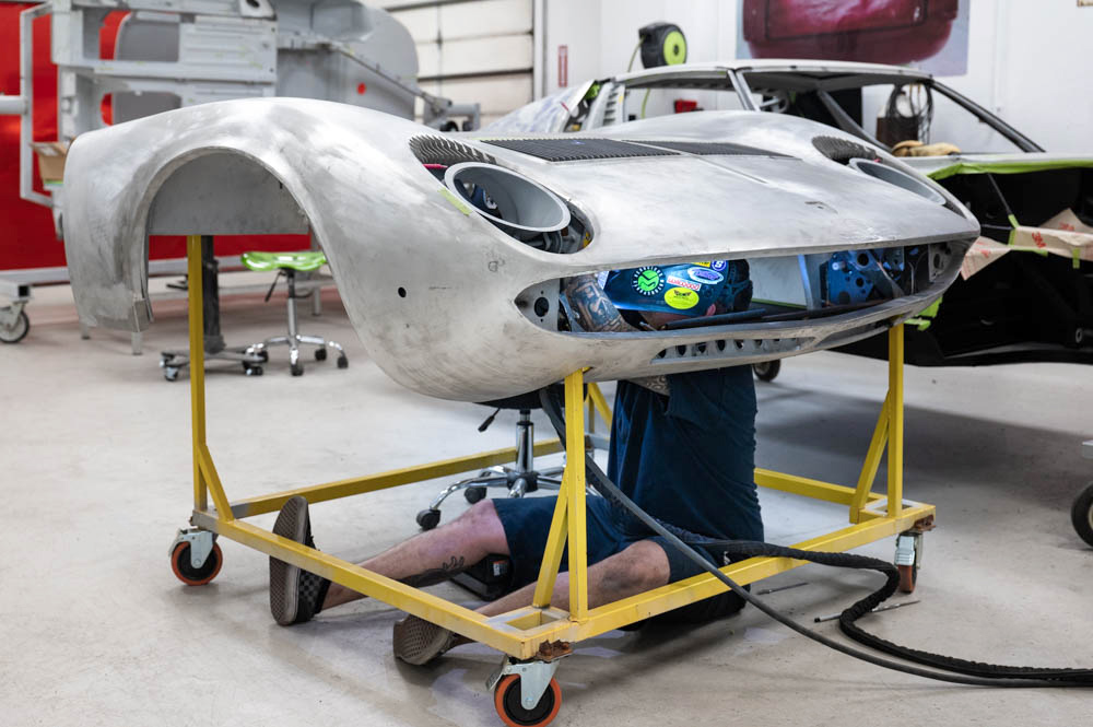
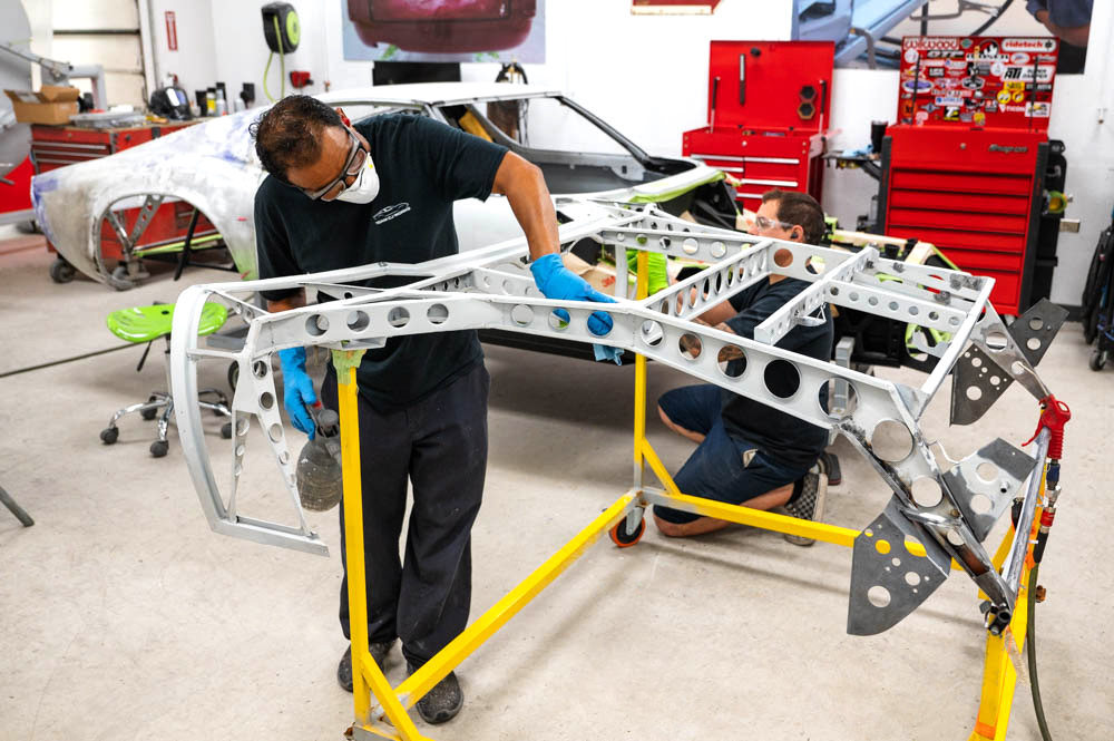
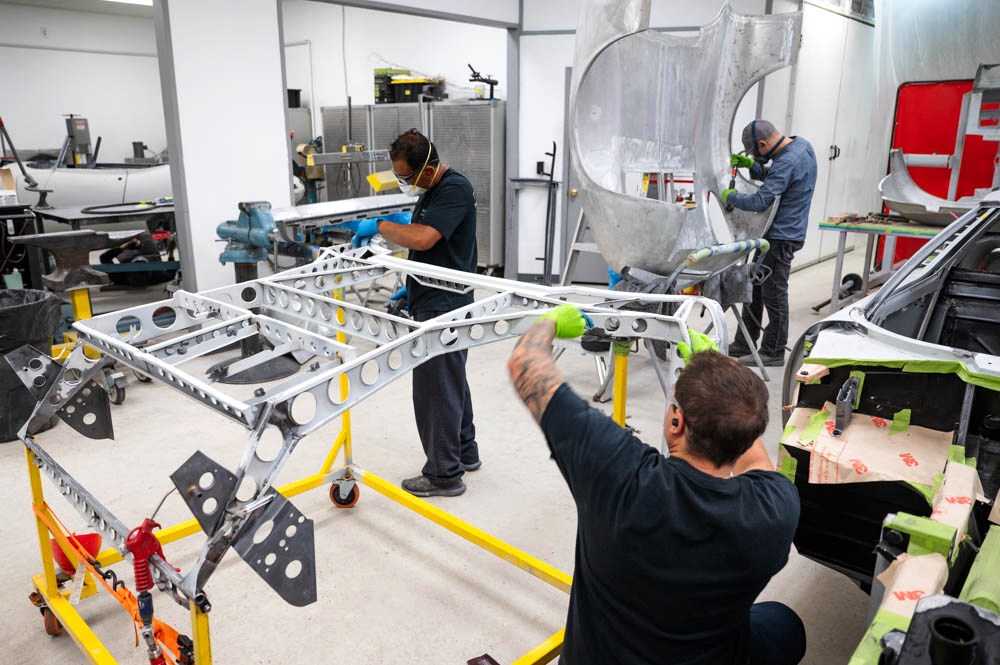
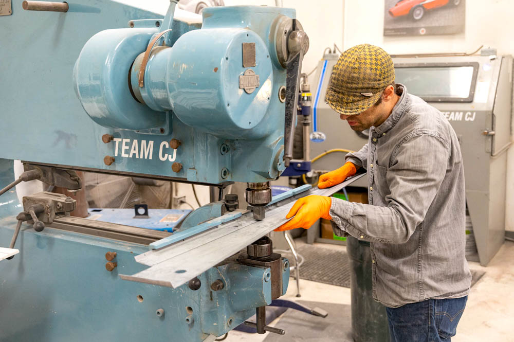
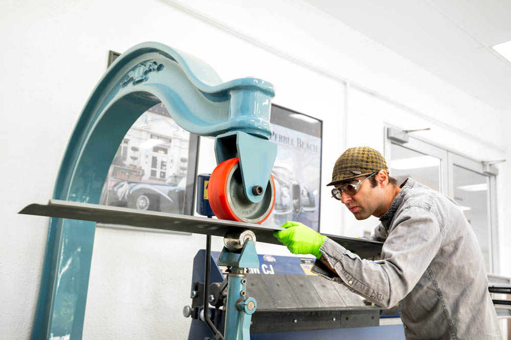
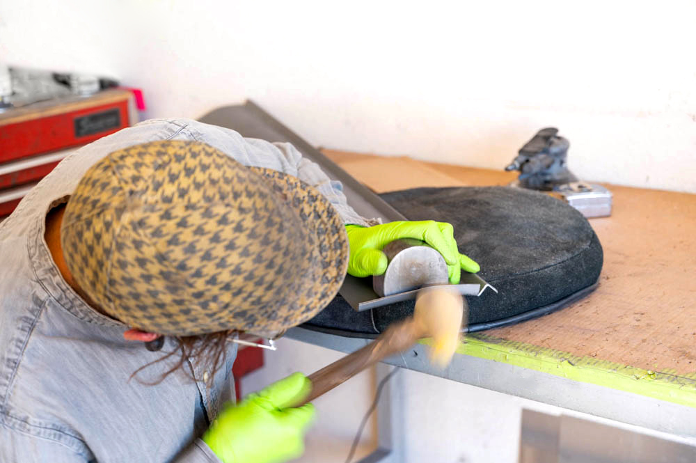
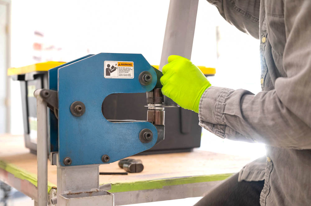
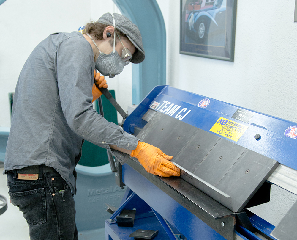
Beginning slat adjustment and profiling
Update report - September 13,
2022
Update report - August 22, 2022
Update report - August 11, 2022
Update report - July 15, 2022
Update report - July 5, 2022
Update
report - May20, 2022
Update report - May 5,
2022
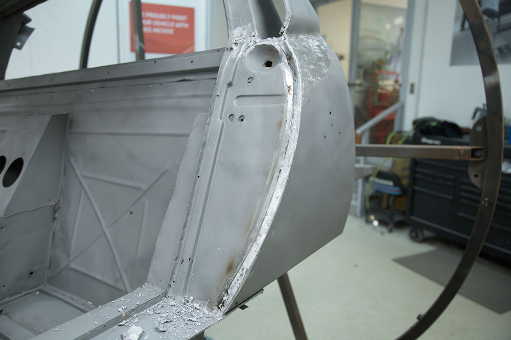
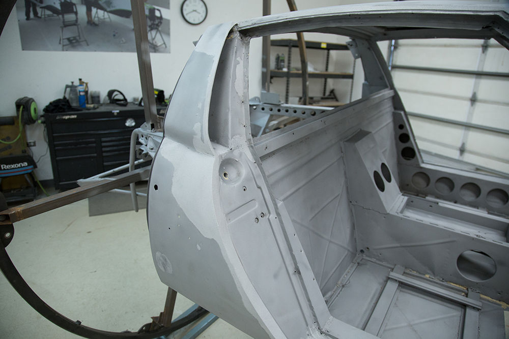
Update
report - April 6, 2022
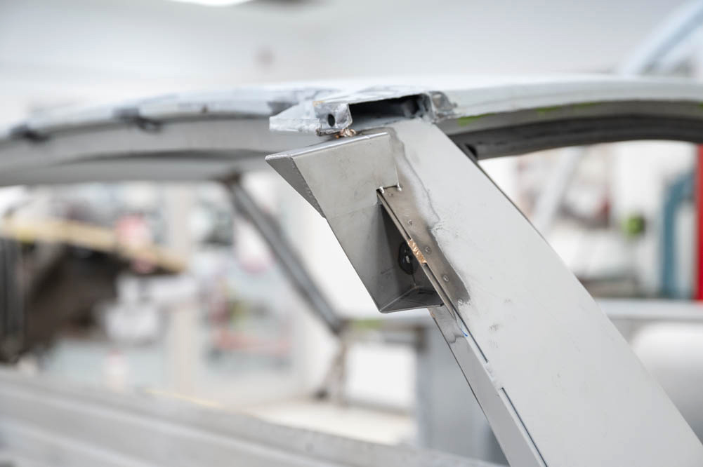
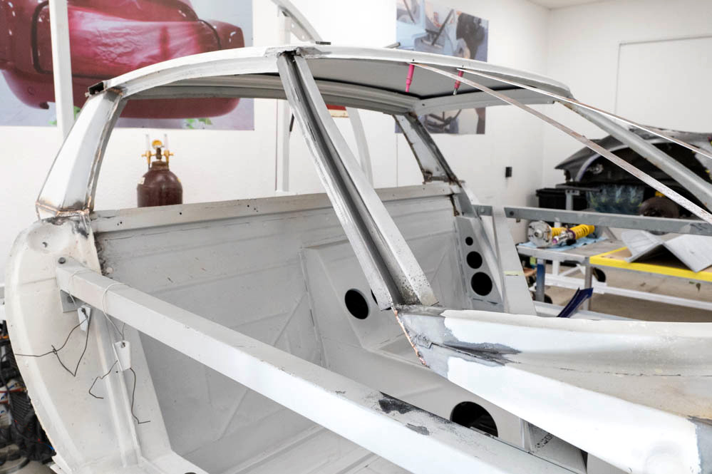
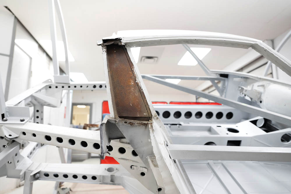
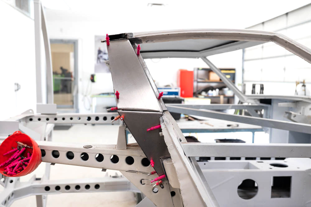
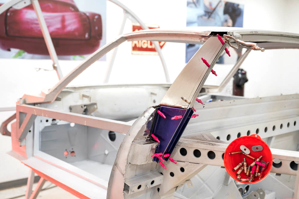
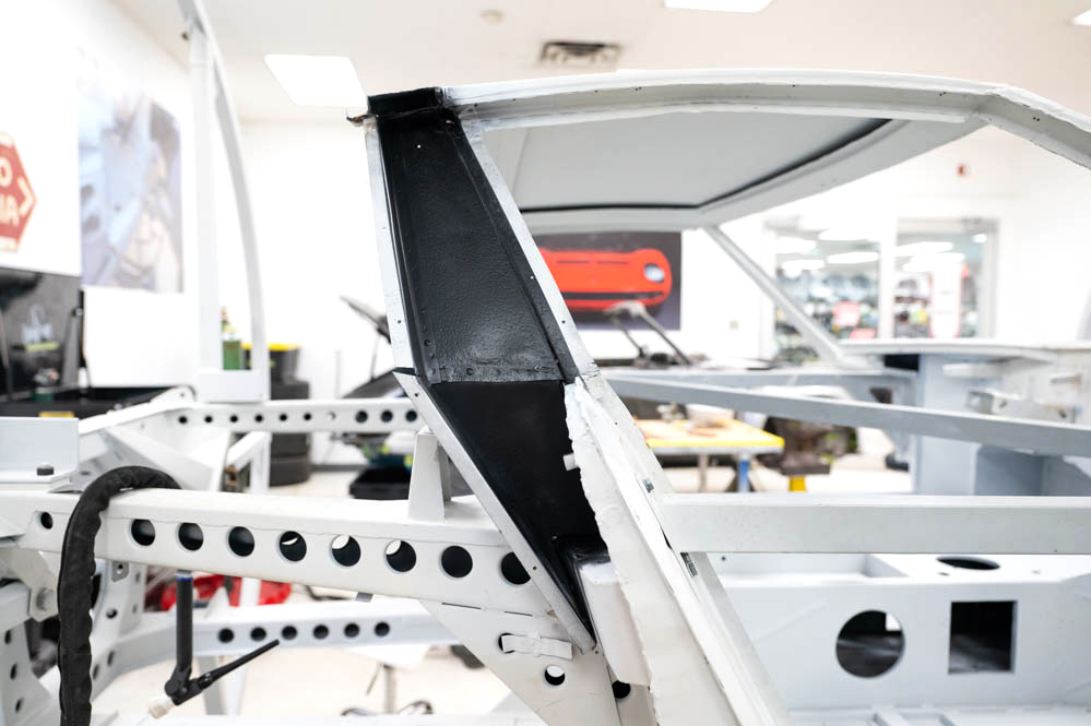
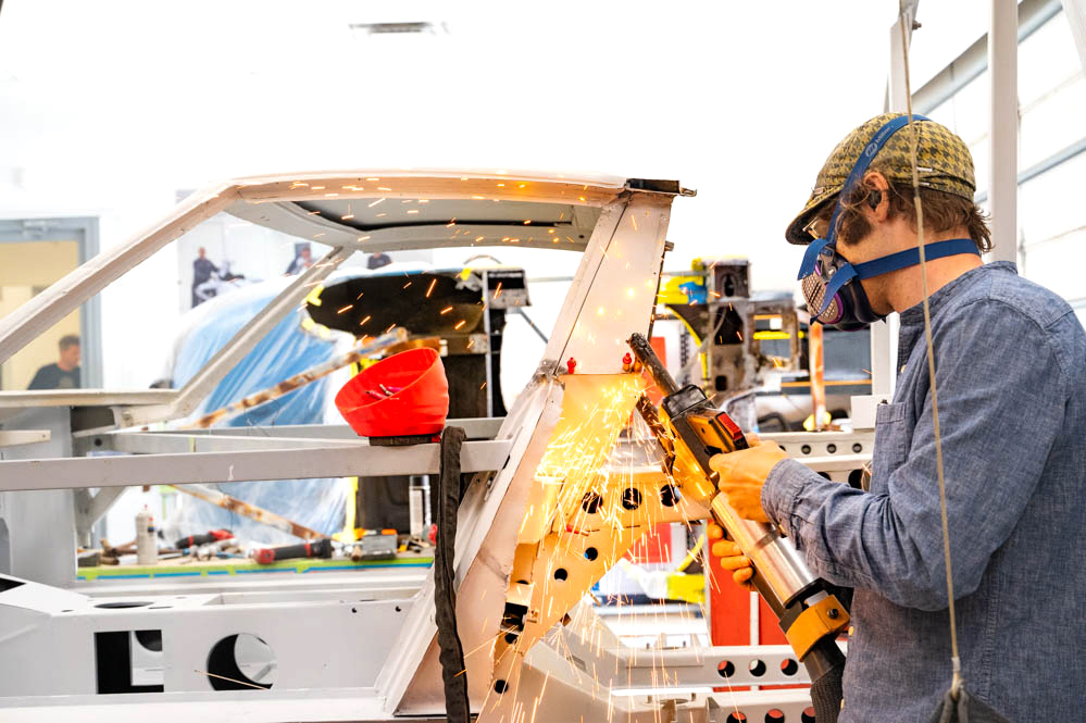
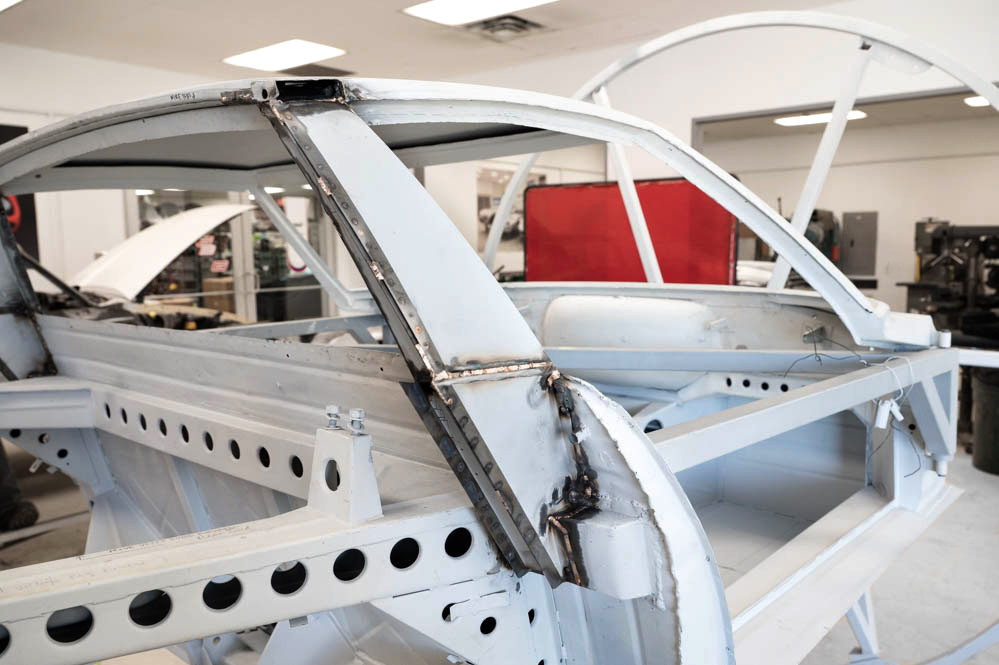
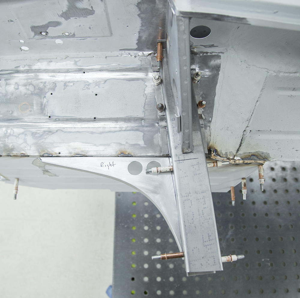
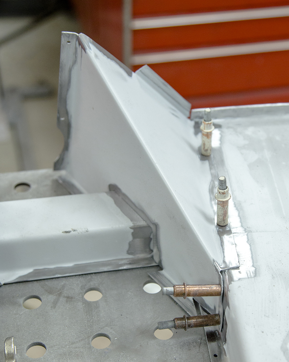
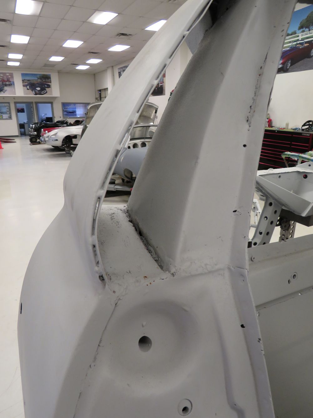
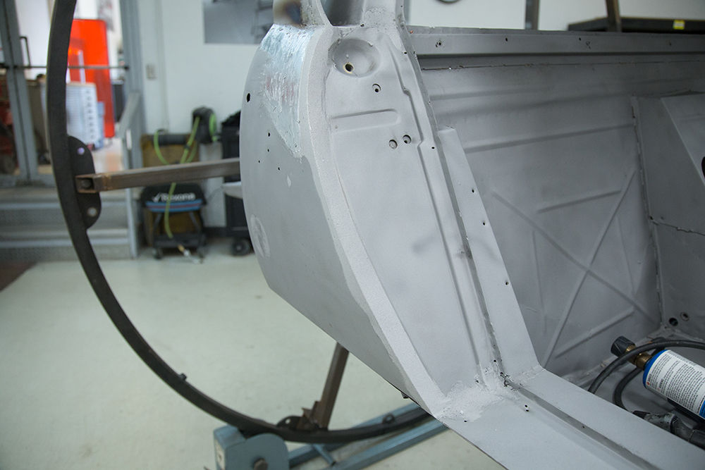
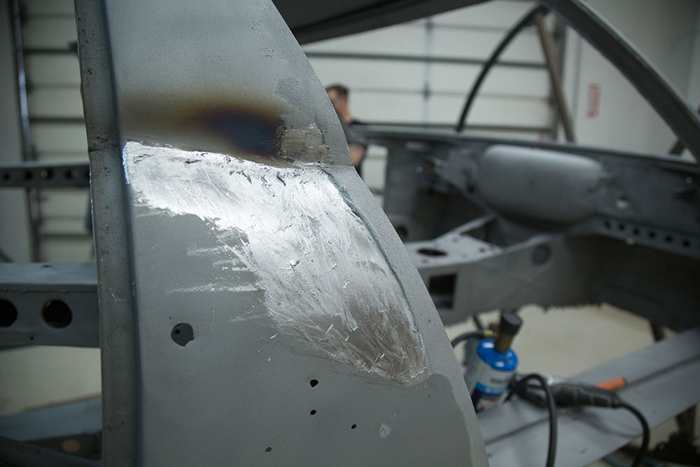
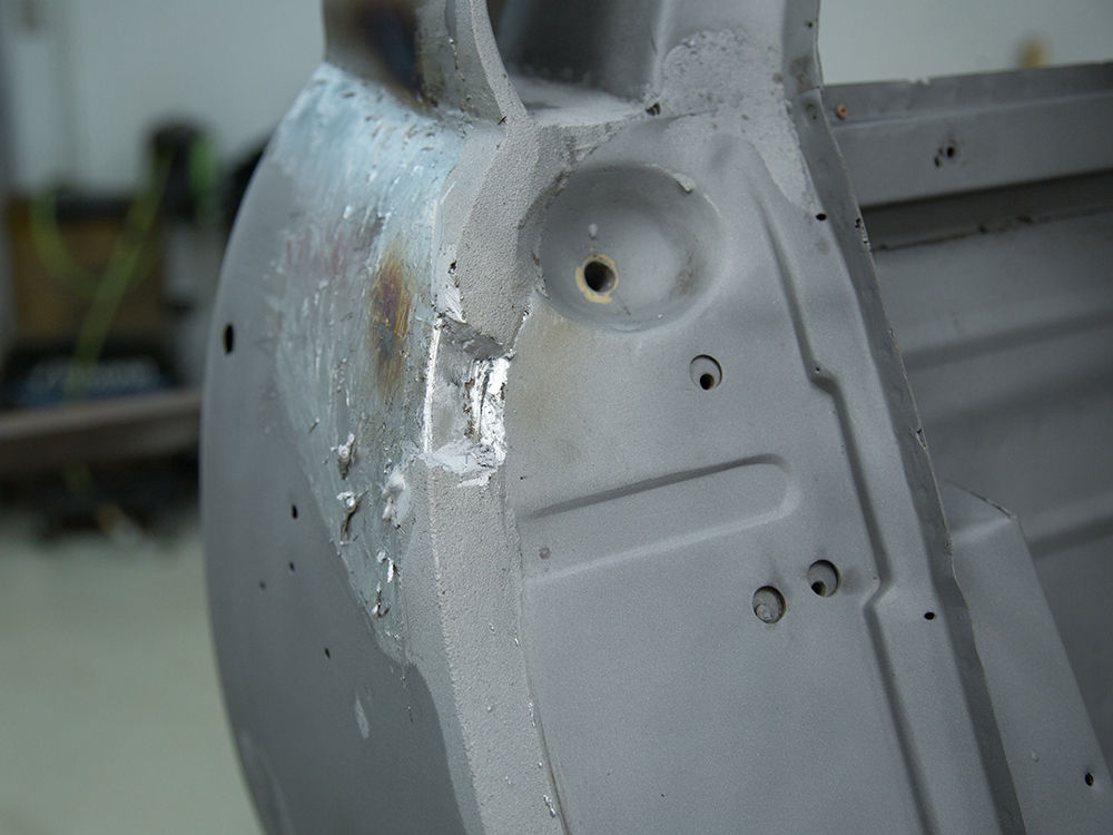
A
pillar work.
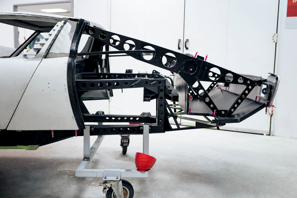
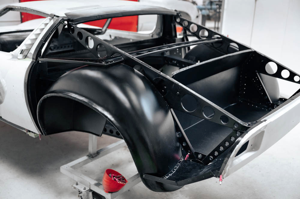
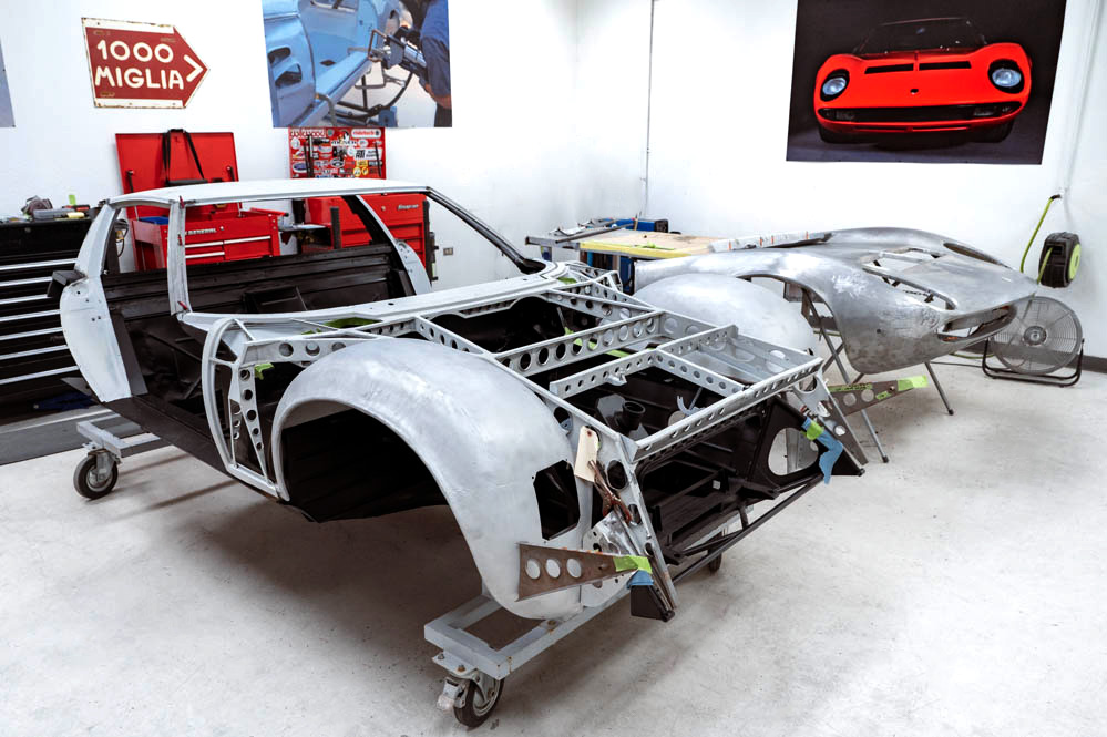
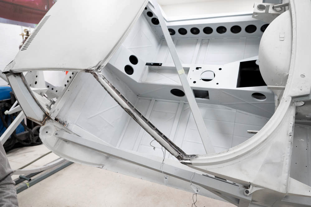
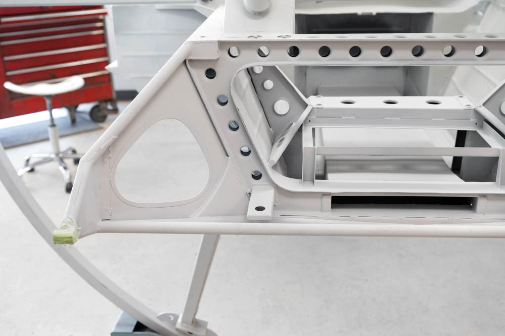
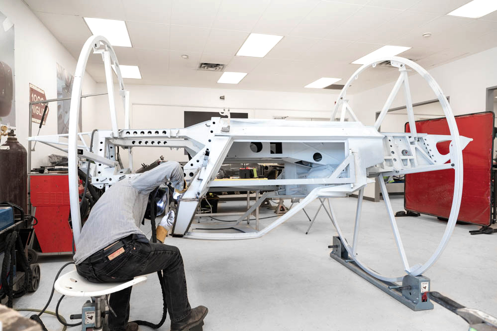
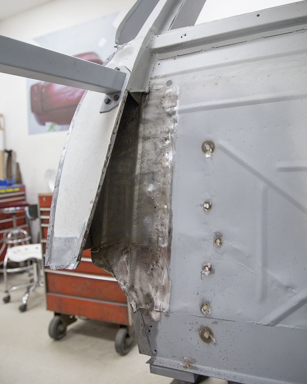
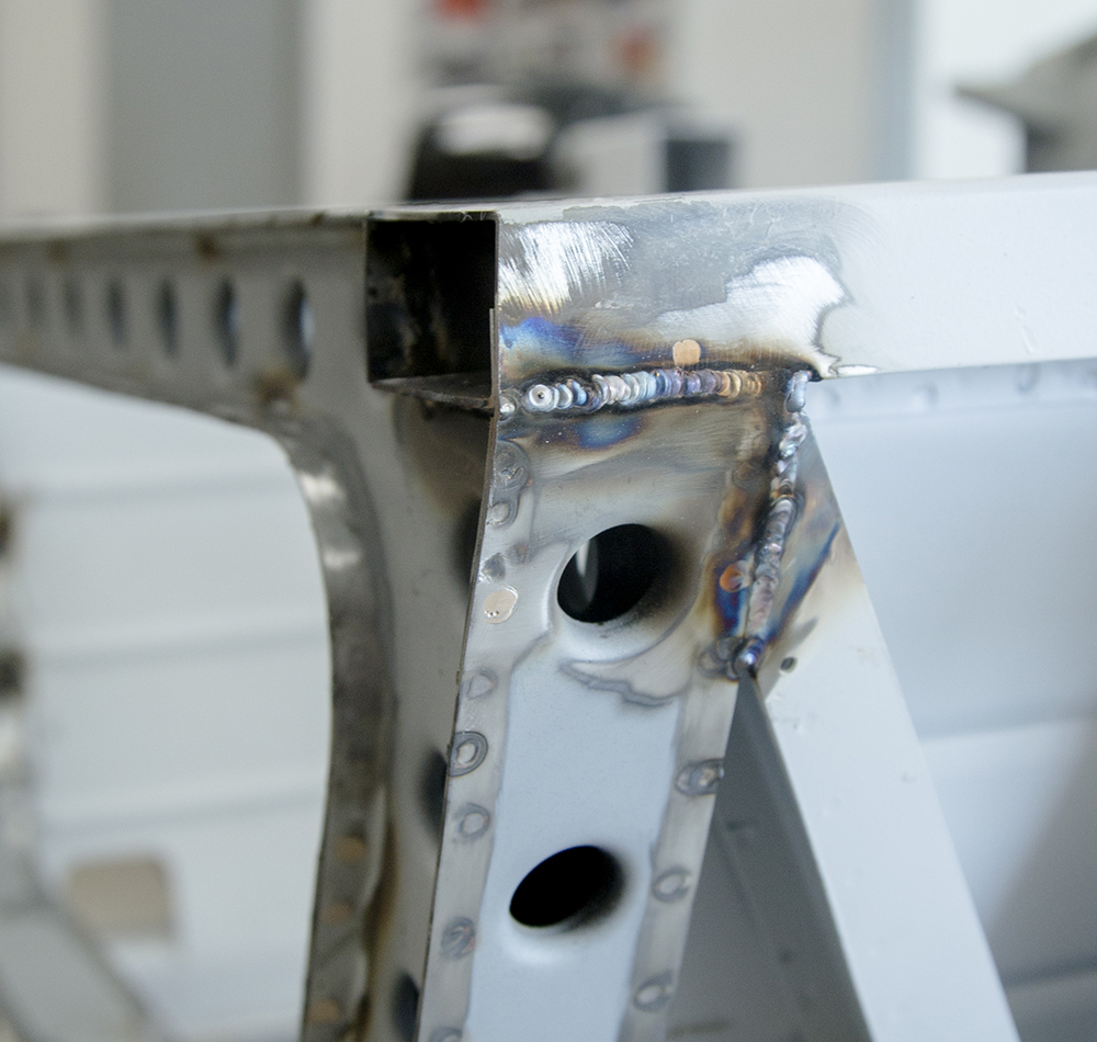
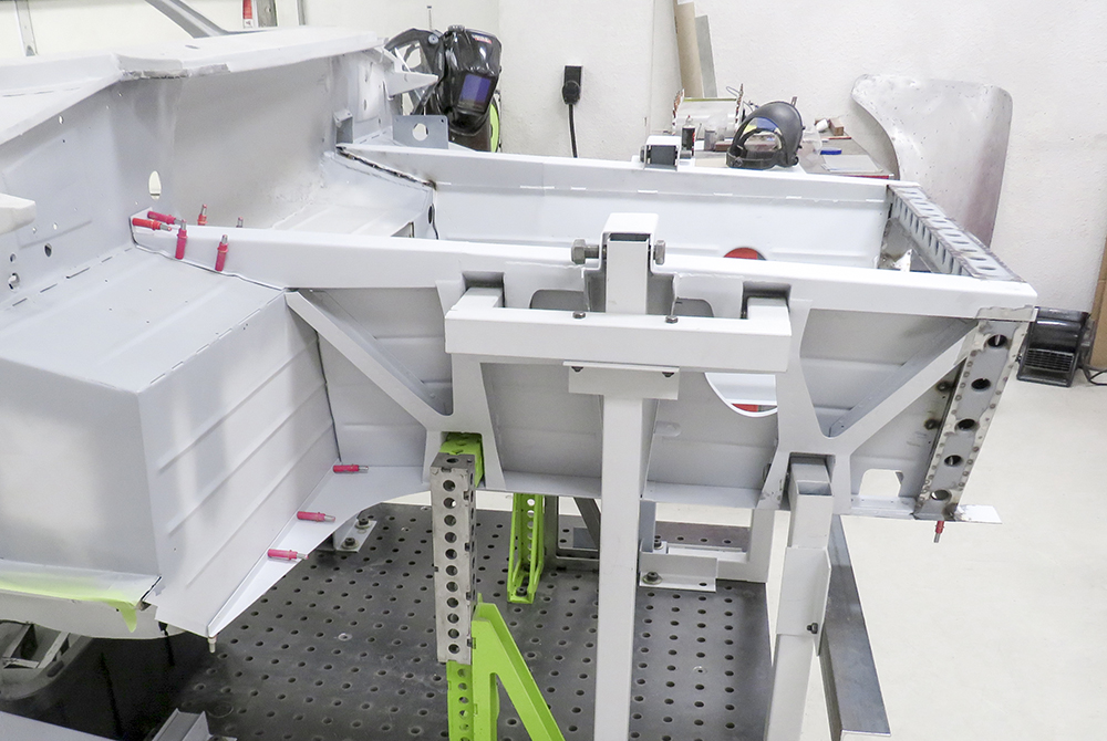
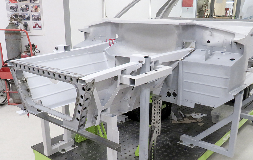
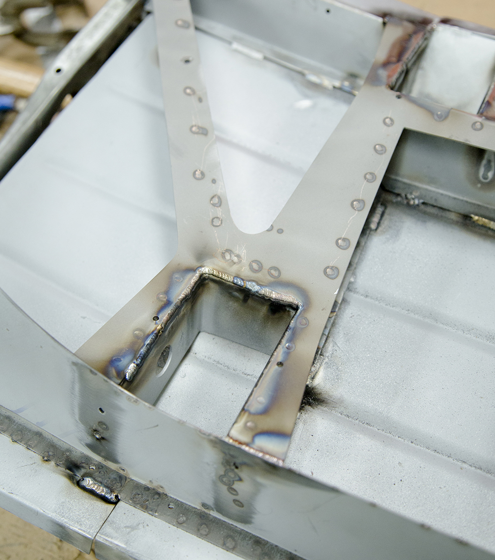
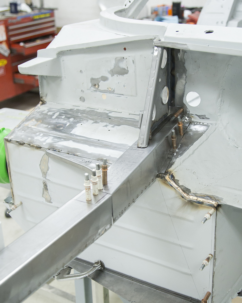
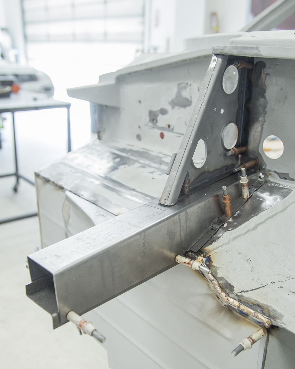
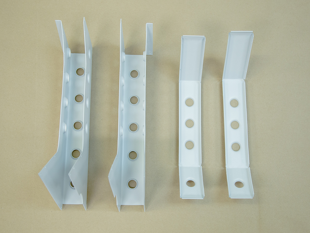
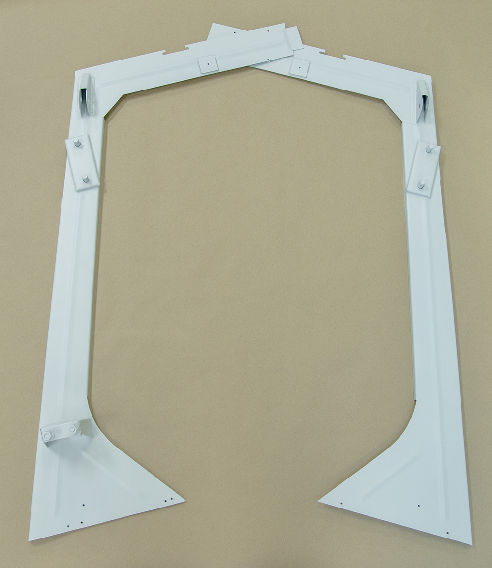
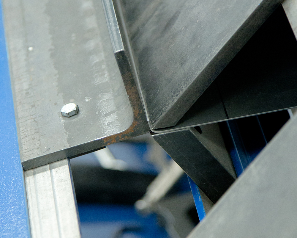
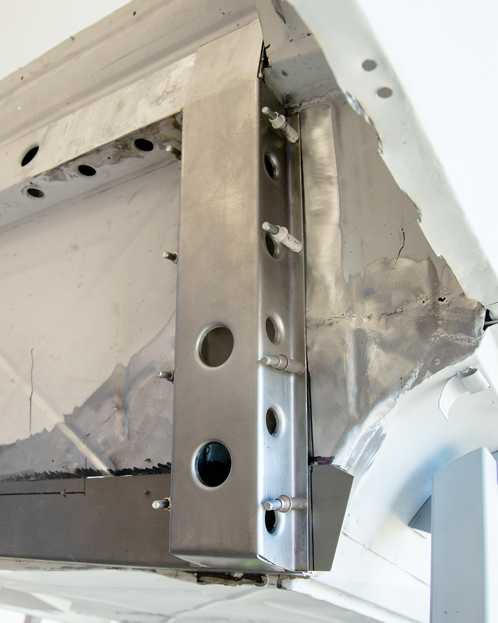
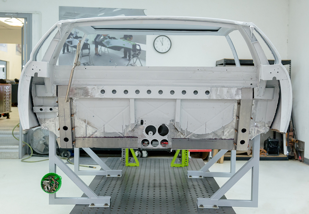
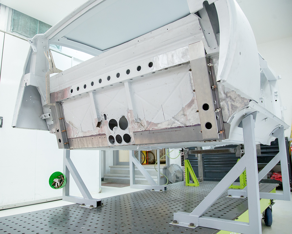
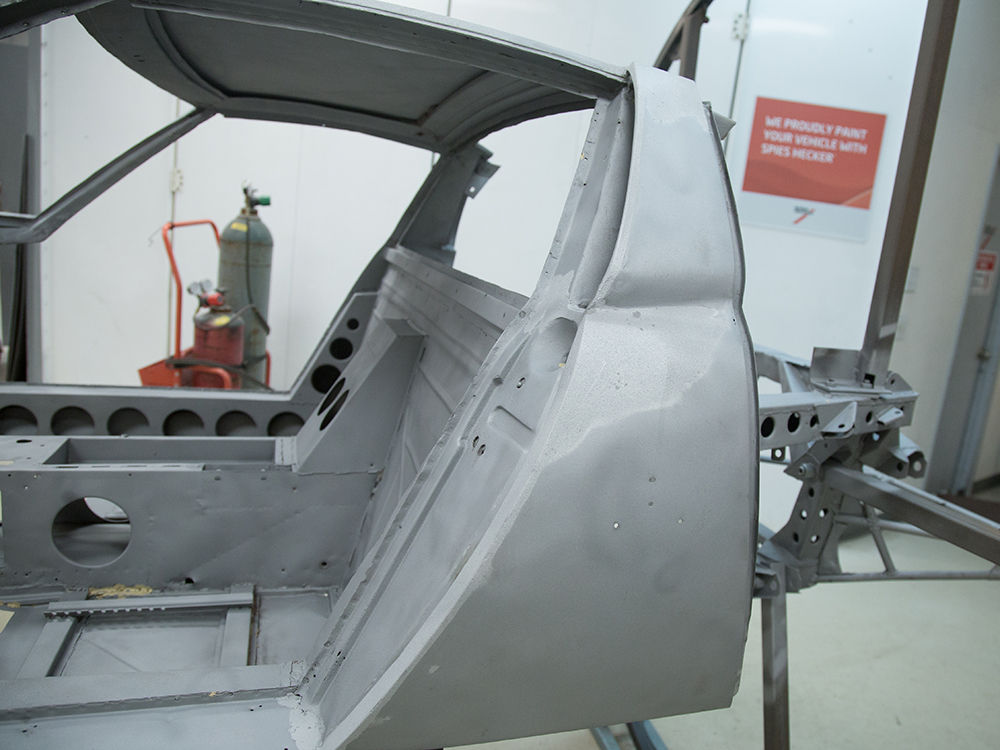
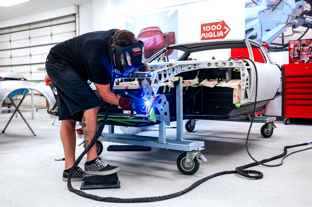
Update report - March 31, 2022
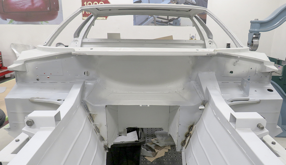
Front superstructure
complete and new b pillar structures fabricated and
installed.
Update report - March 10,
2022
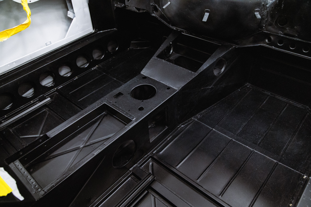
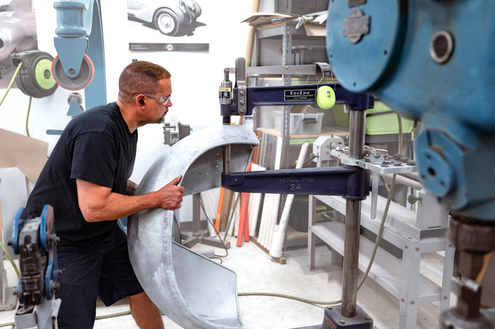
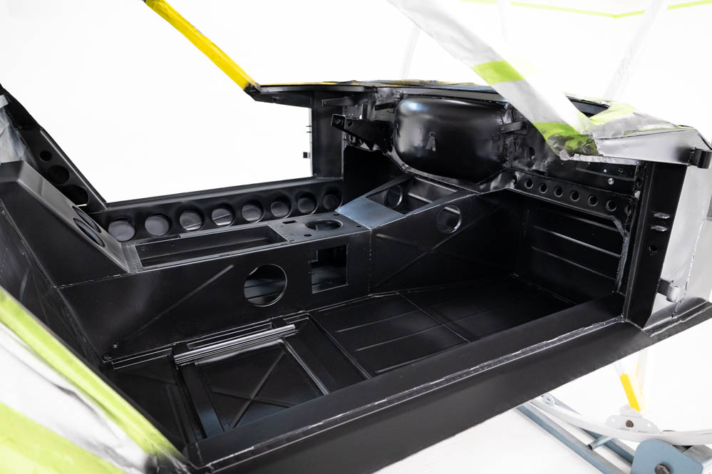
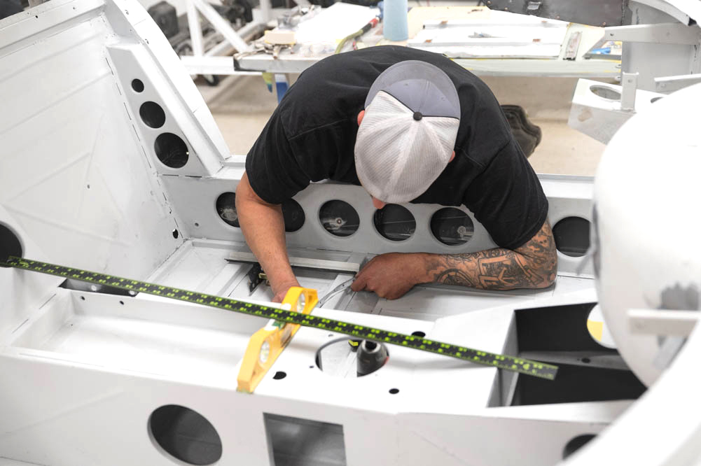
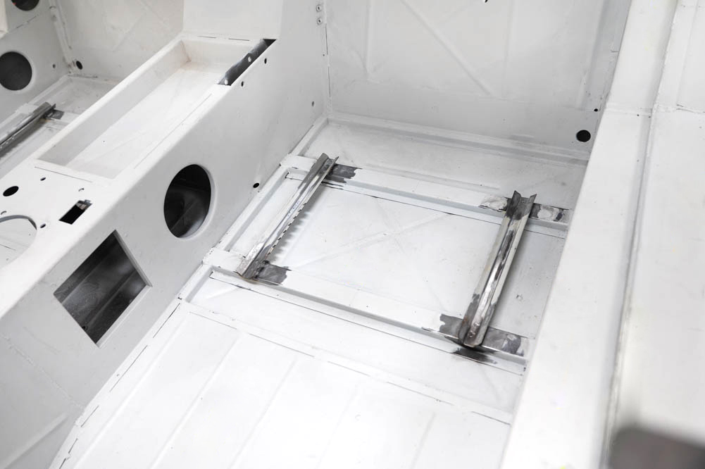
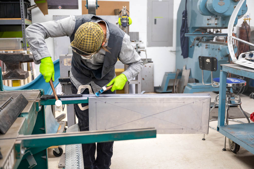
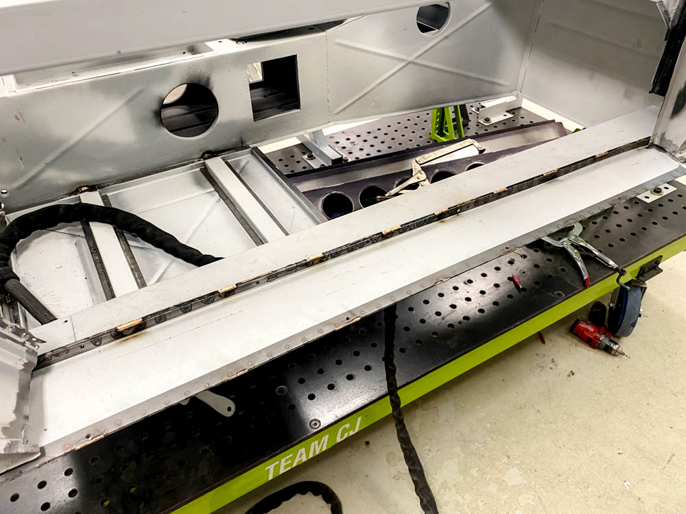
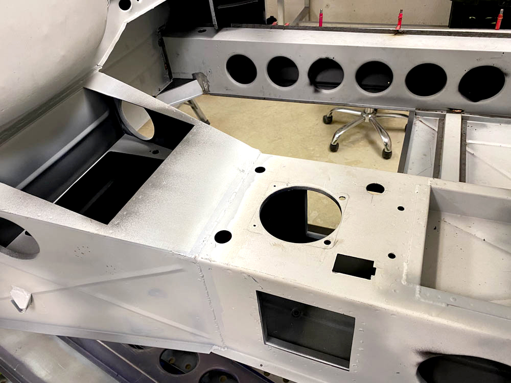
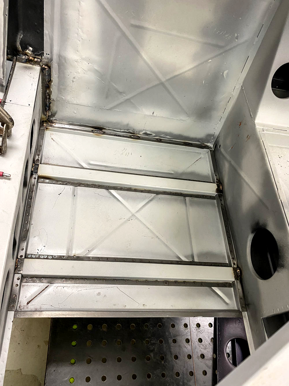
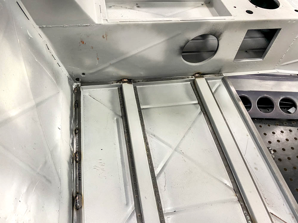
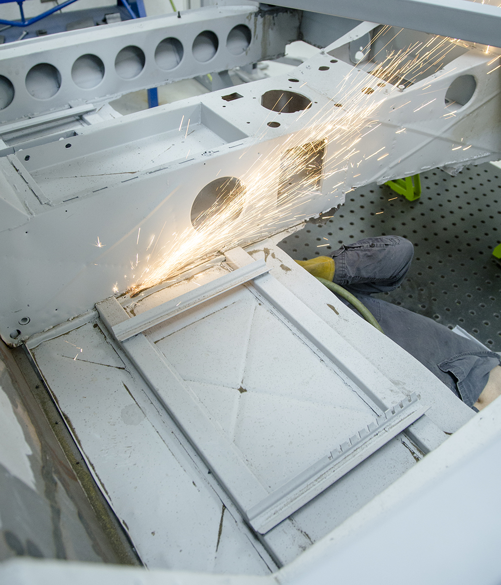
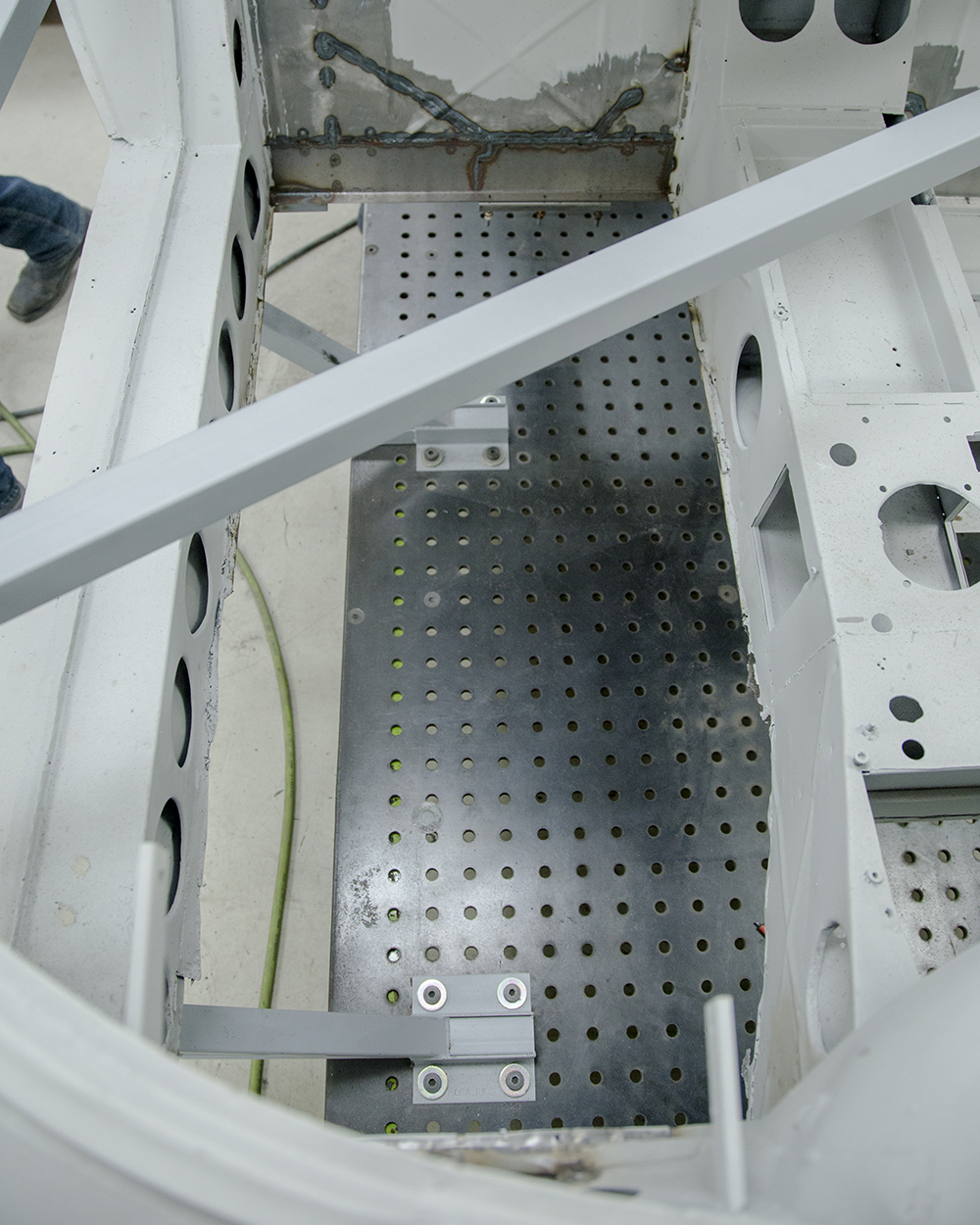
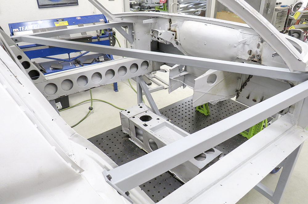
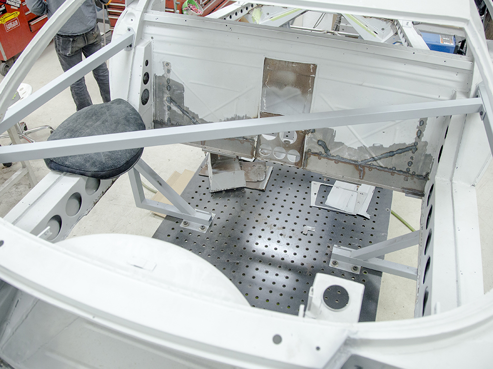
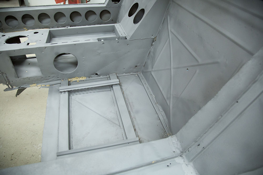
Andy has made great
progress in the coachworks including the completed floor.
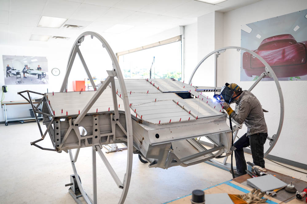
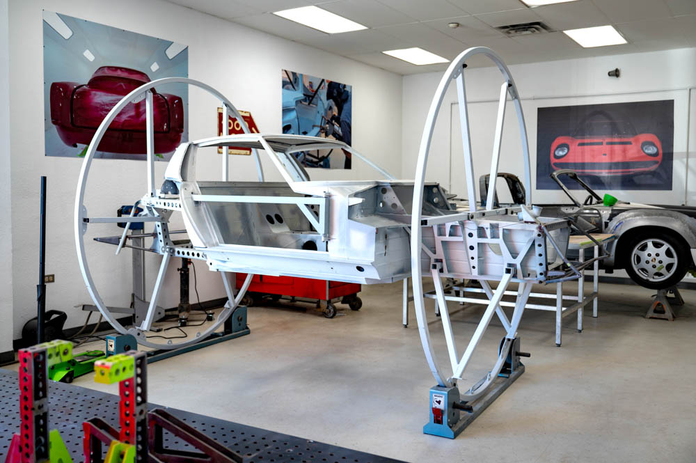
Update report - January 7, 2022
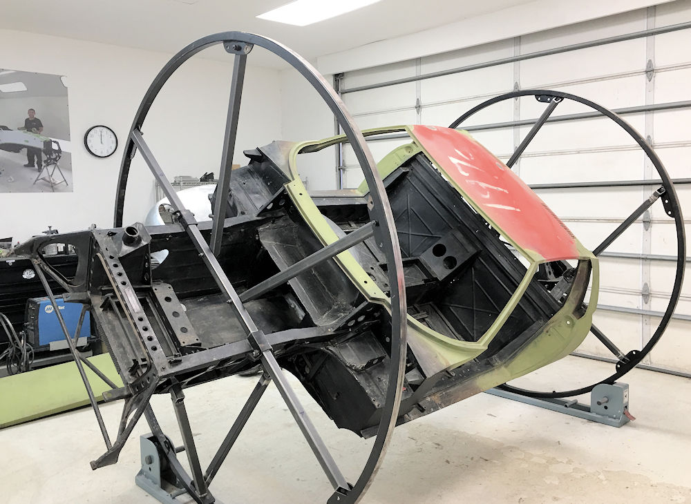
On the rotisserie and
continuing fabrication from all angles.
Update report - December 14, 2021
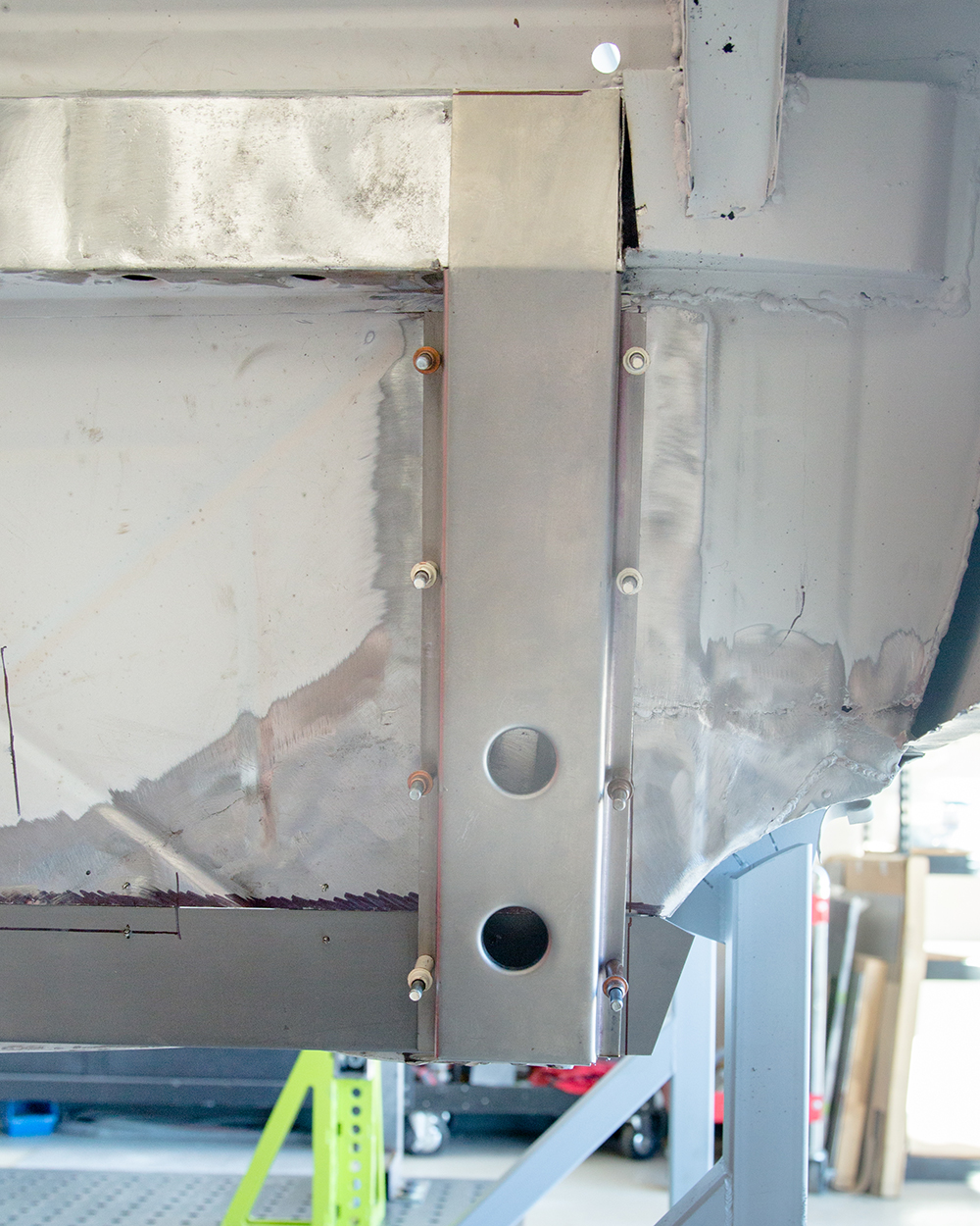
Newly fabricated left
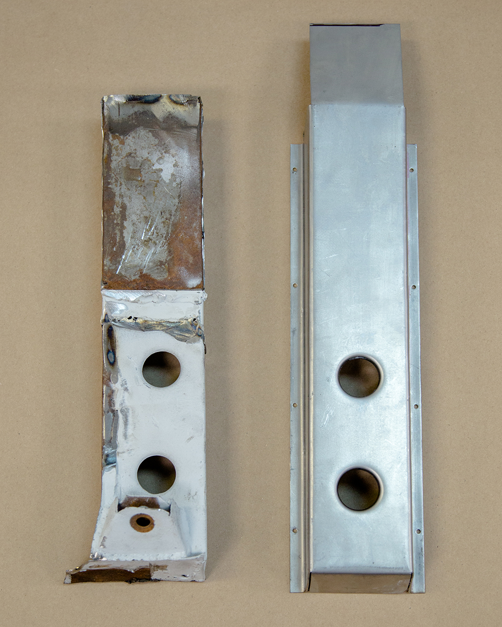
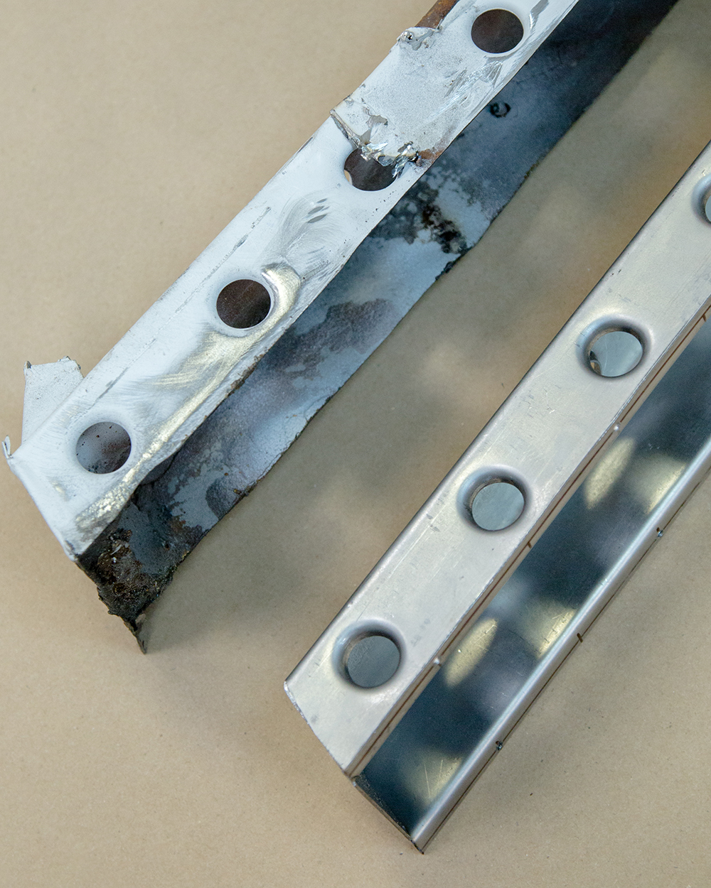
door sill installed.
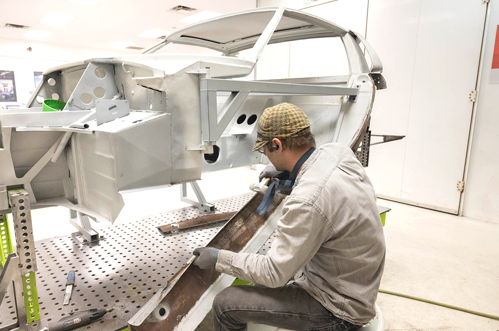
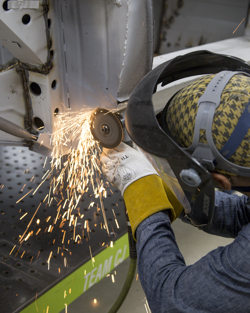
Update report - October 1, 2021
Left door sill has been
removed with areas cleaned and ready for the newly
fabricated door sill.
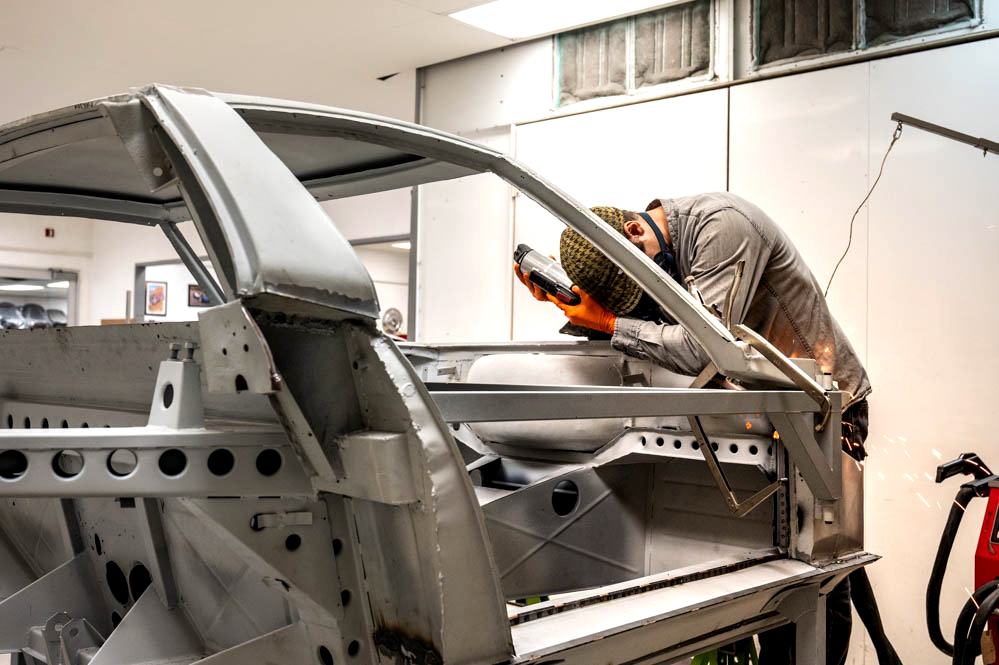
Andy removing the left hand sill panel
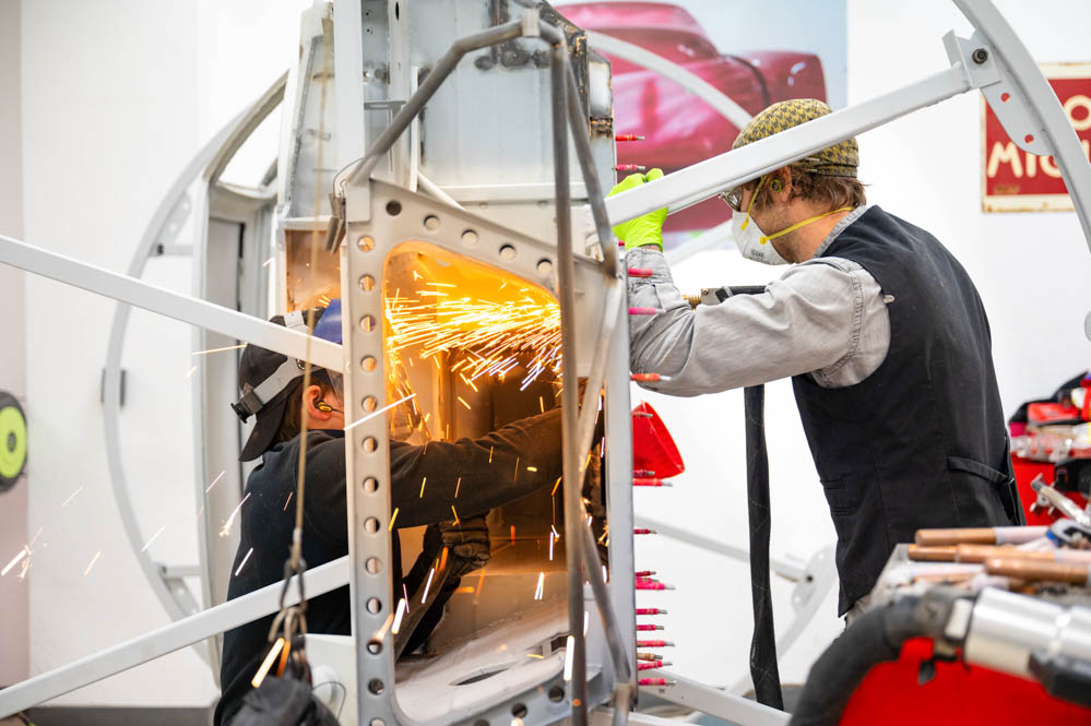
Update report - September 28, 2021
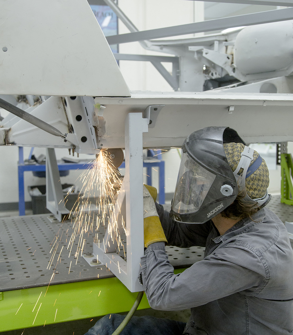
Andy has been making
excellent progress with the sheet metal repairs, and Darien
and Corey have now completed the engine and transaxle
rebuild.
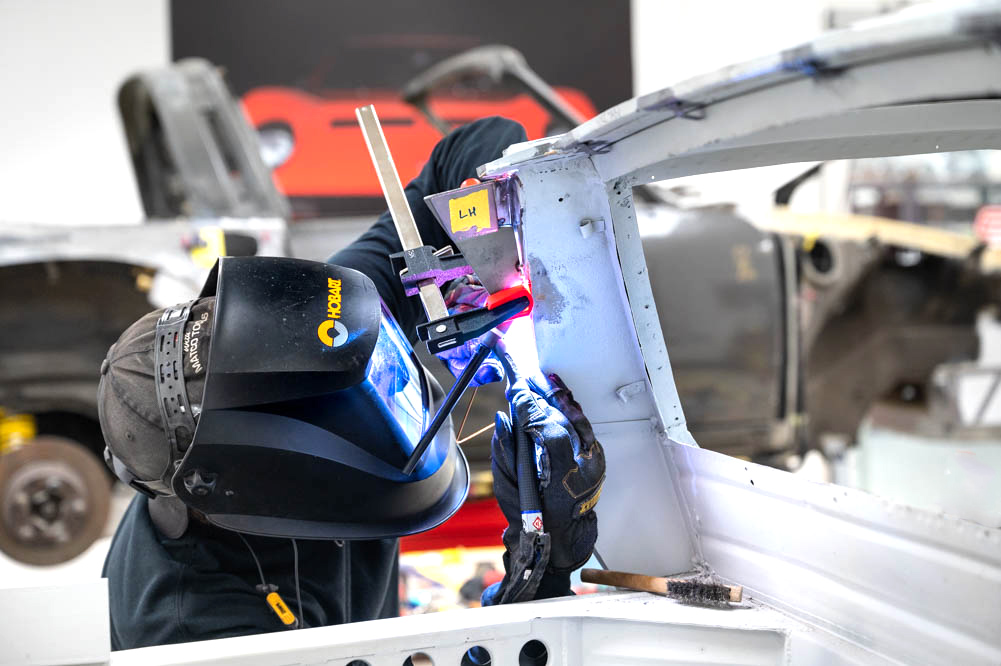
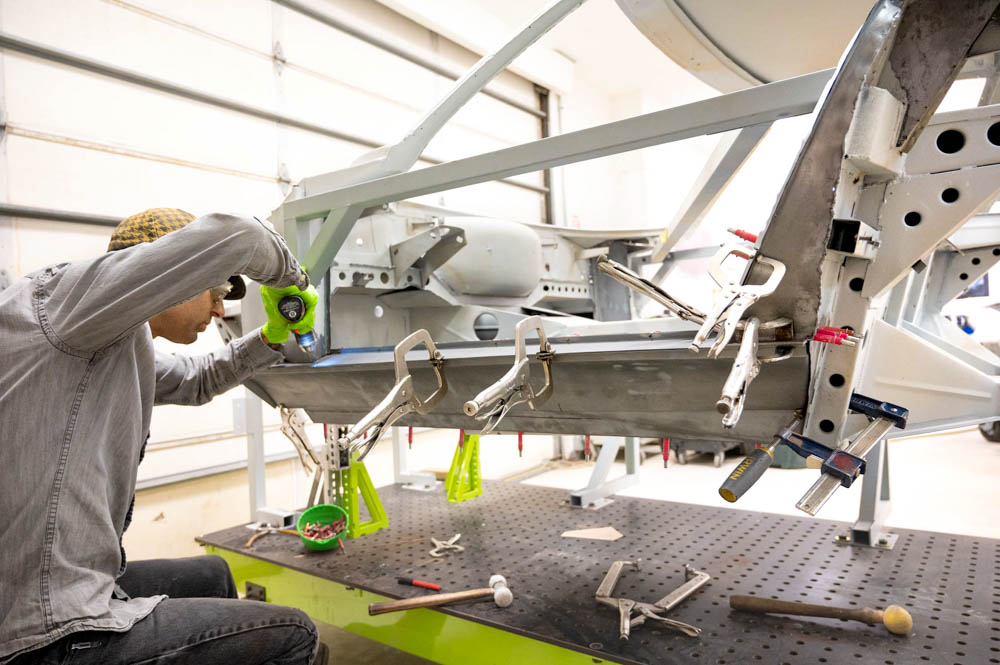
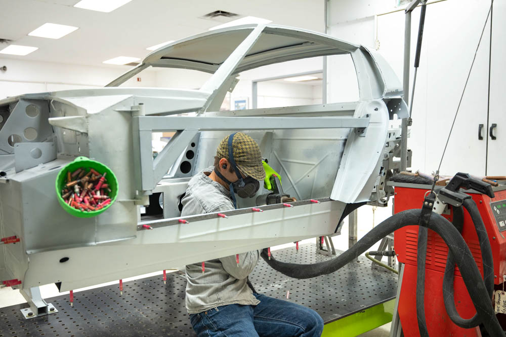
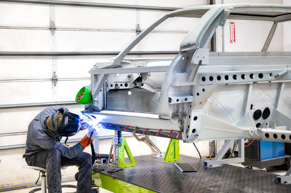
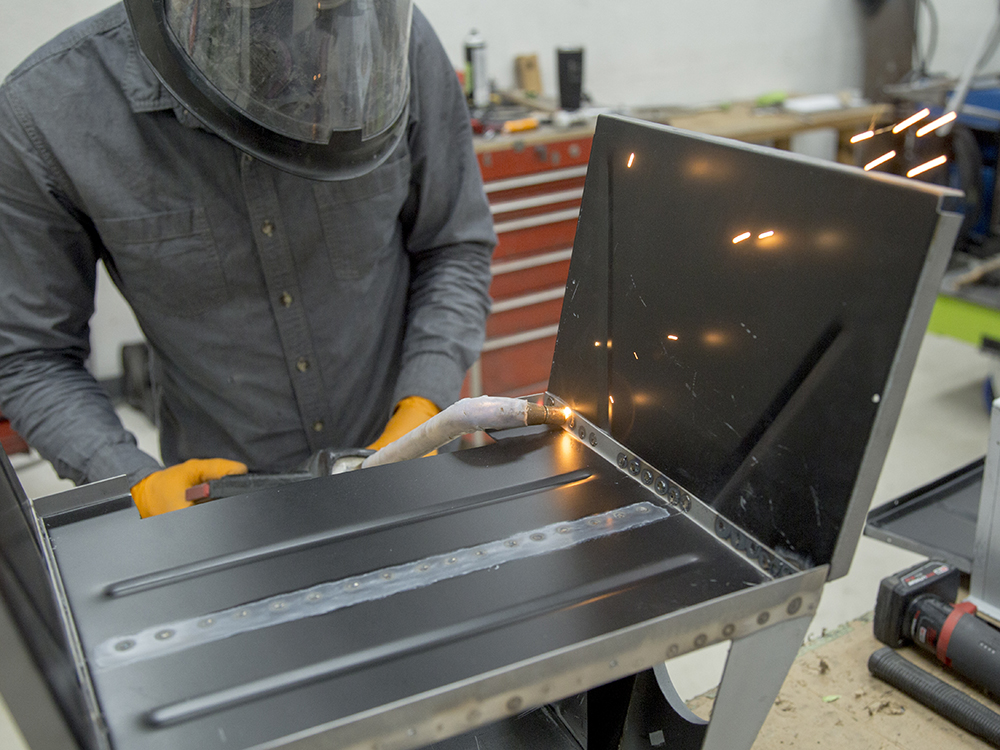
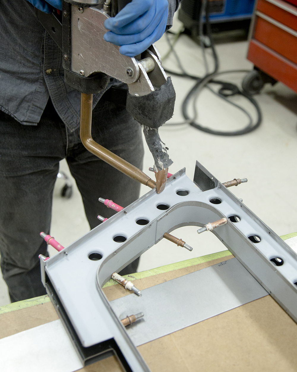
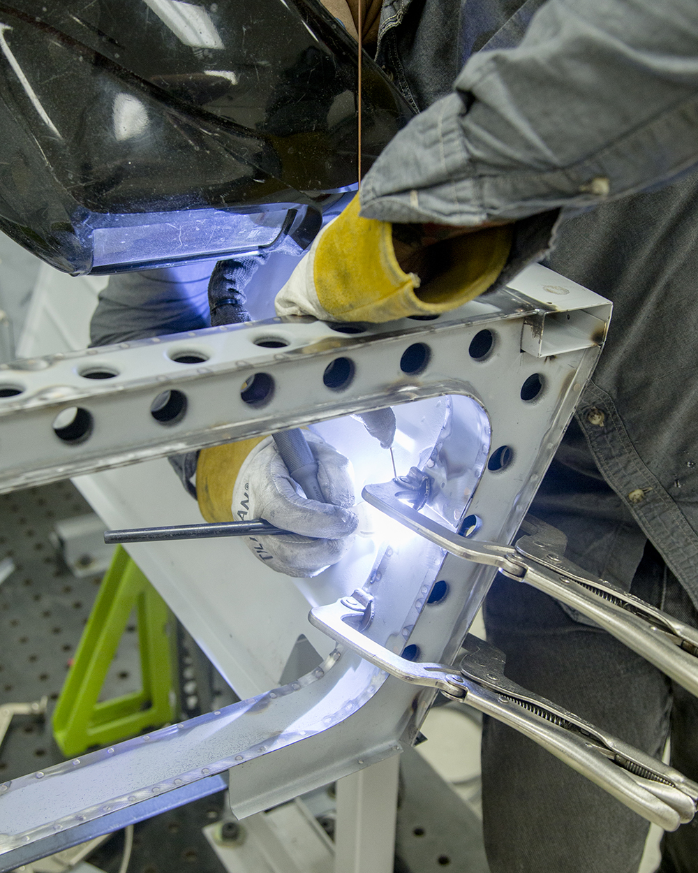
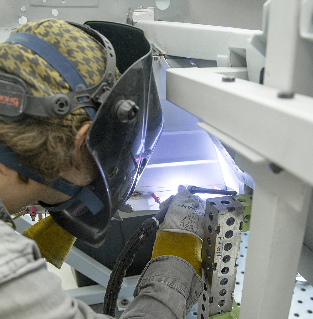
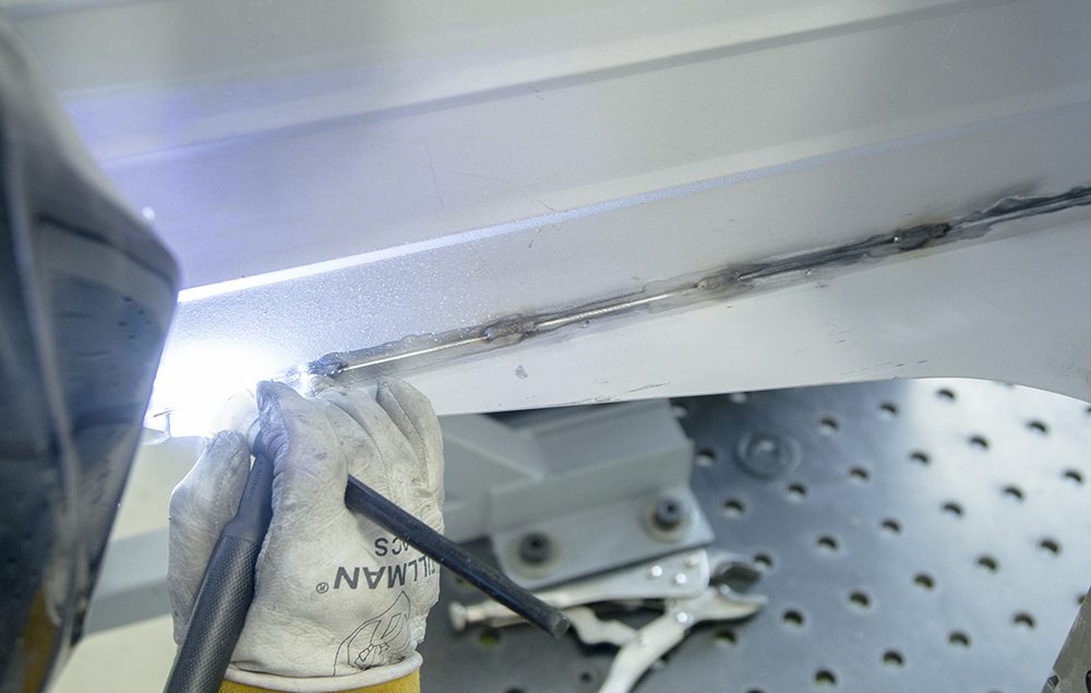
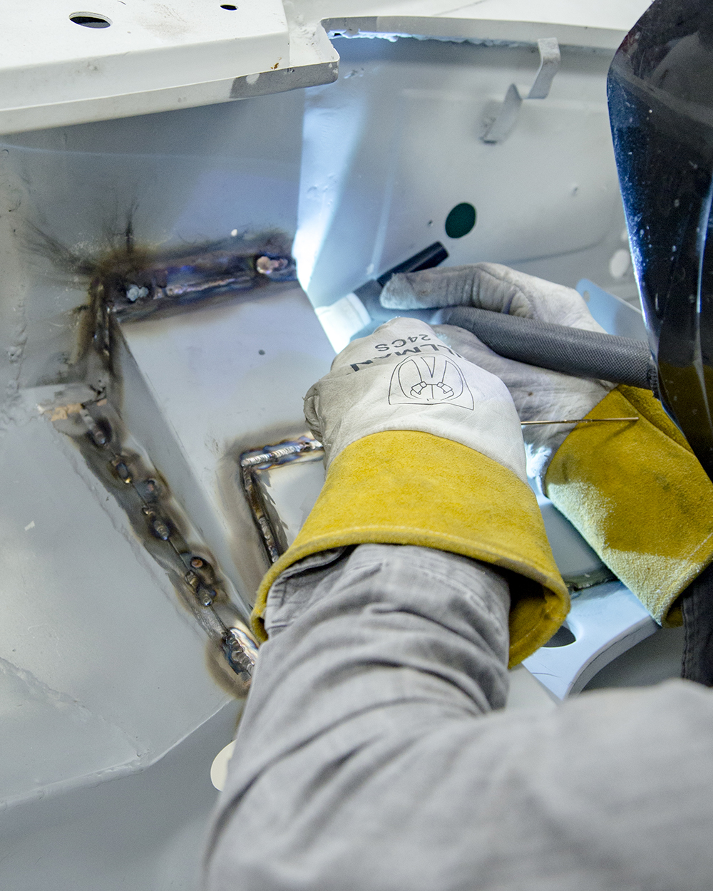
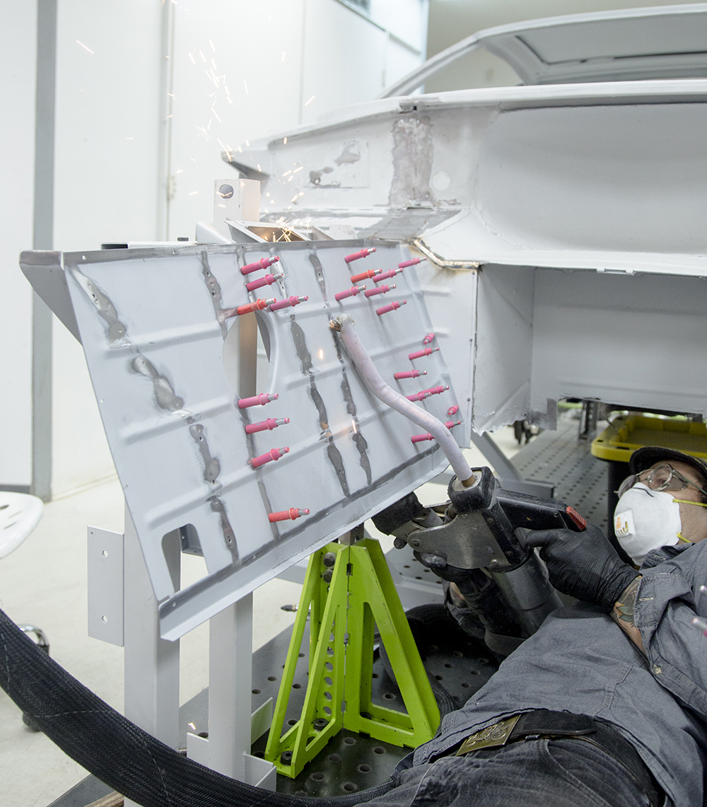
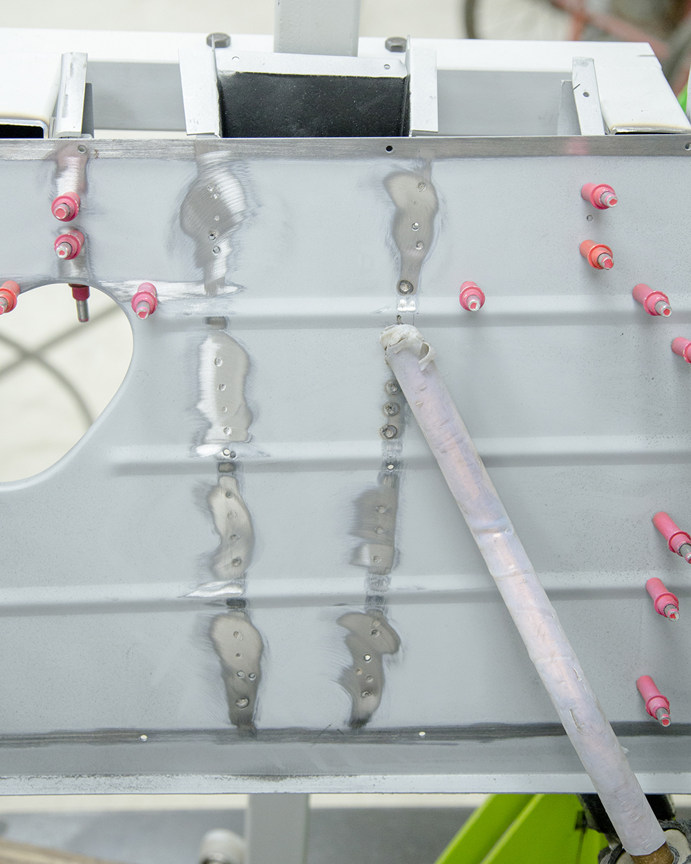
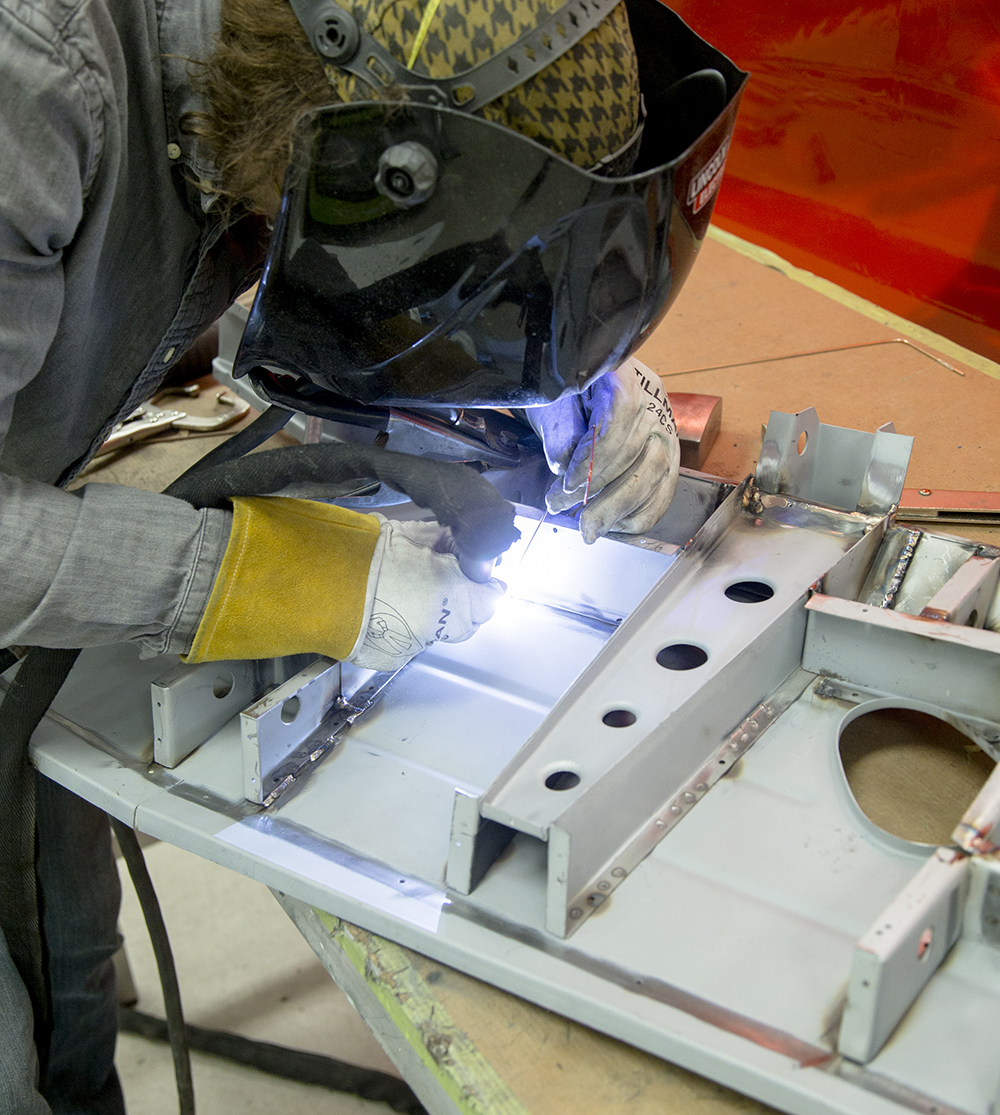
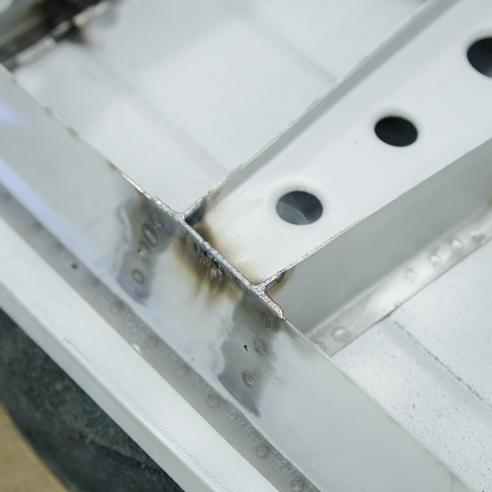
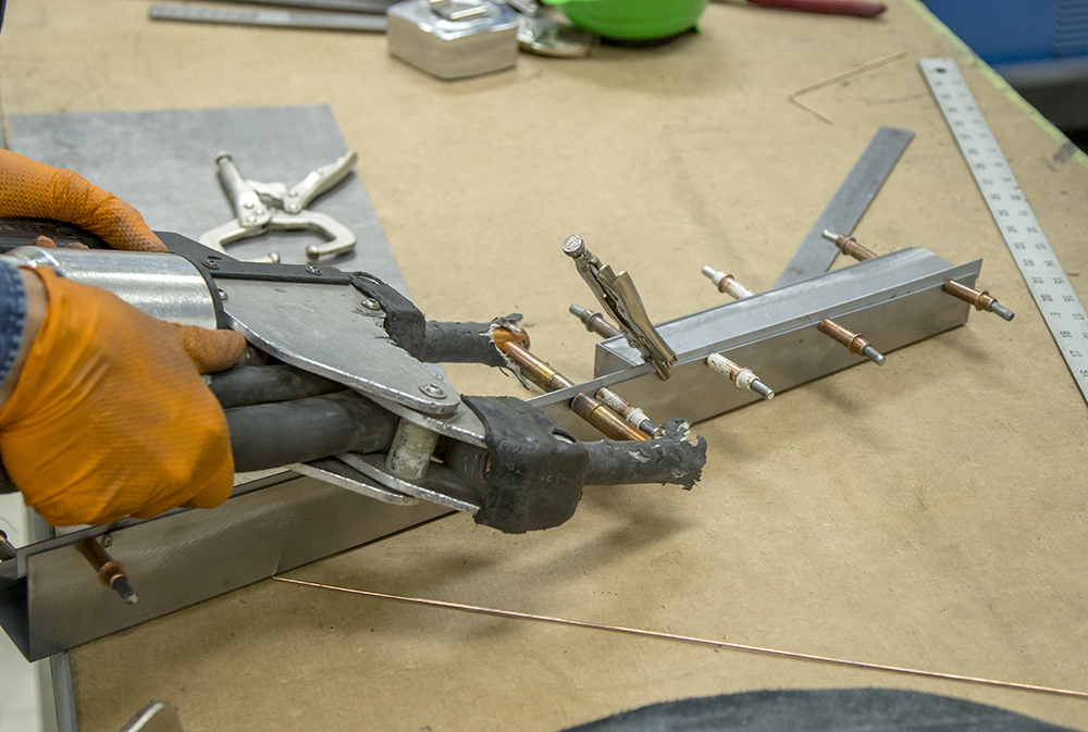
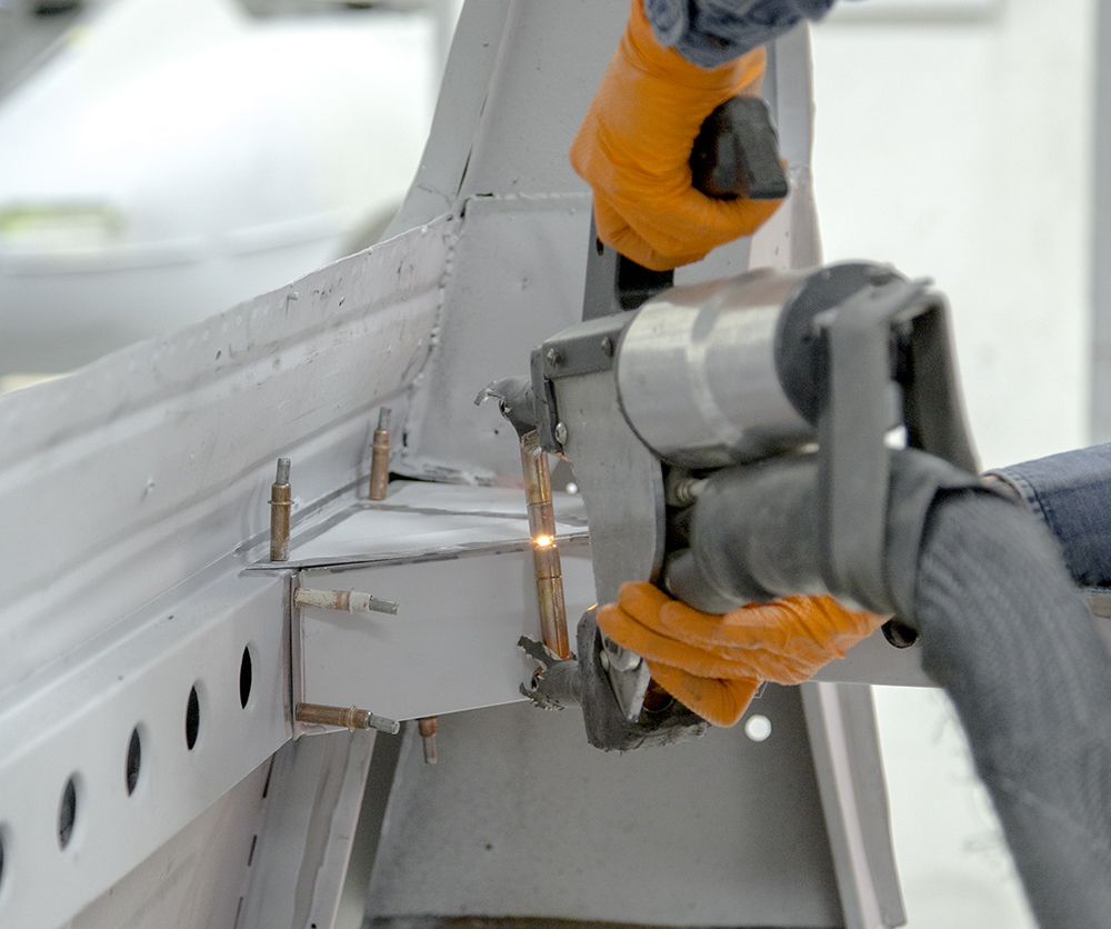
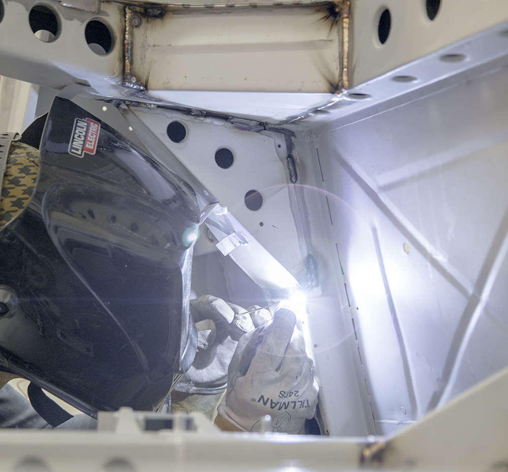
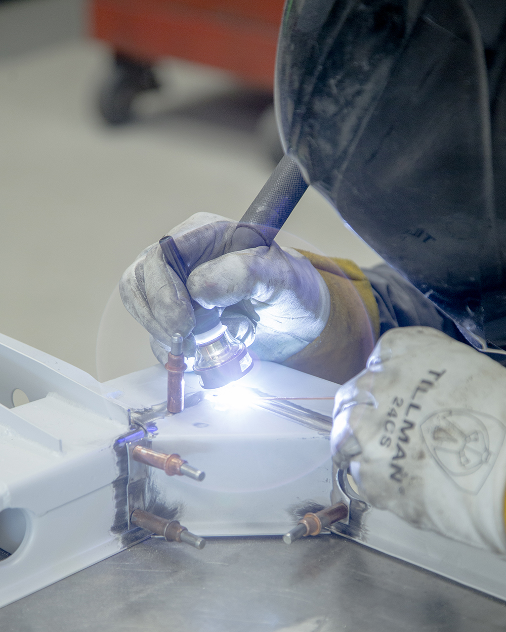
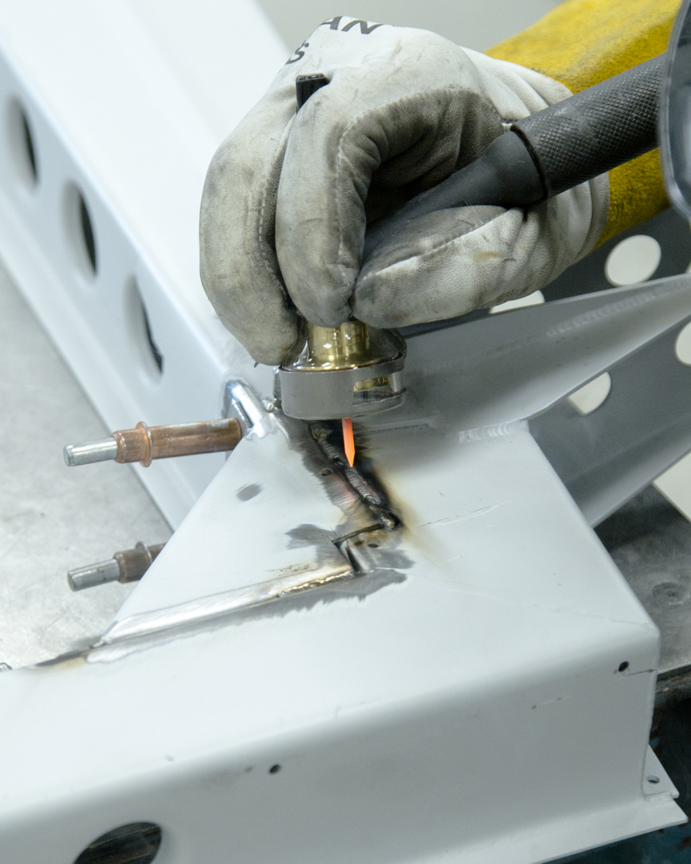
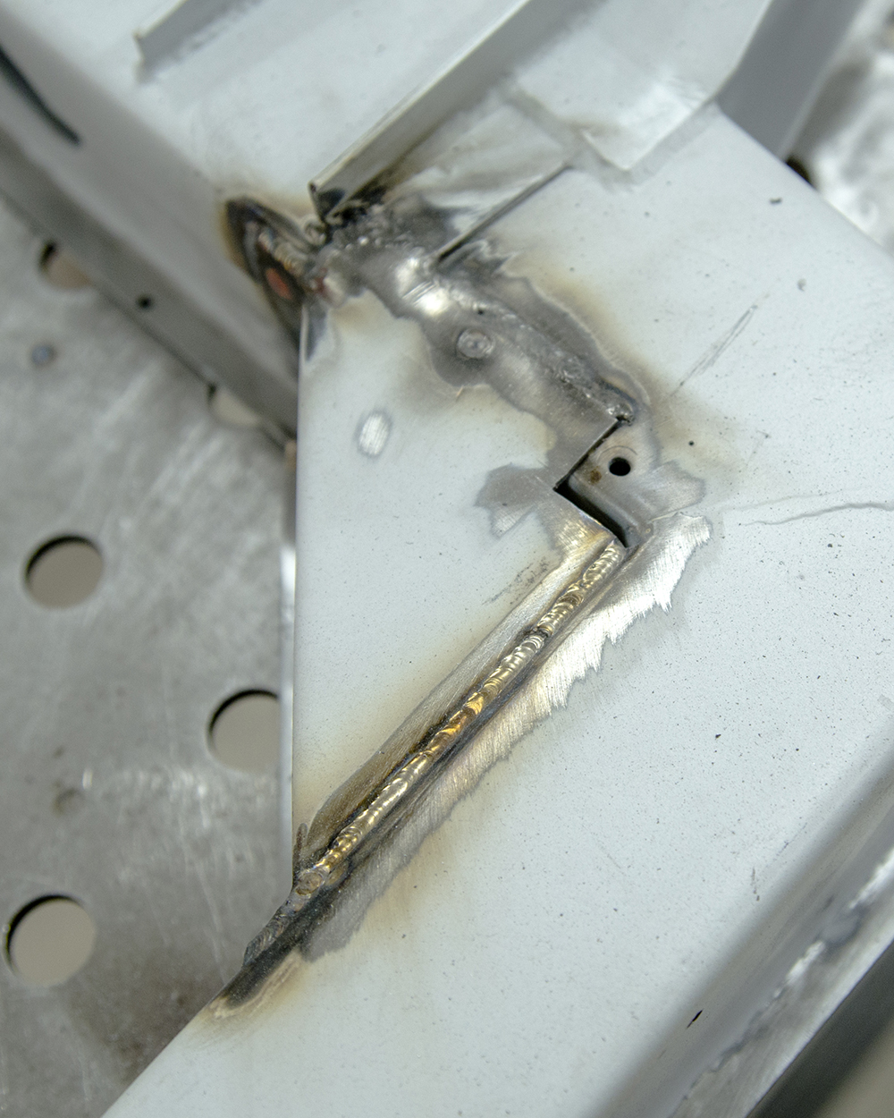
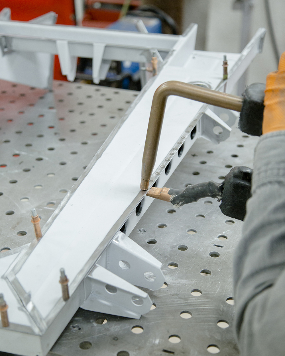
Andy welding the new right hand sill panel in
place
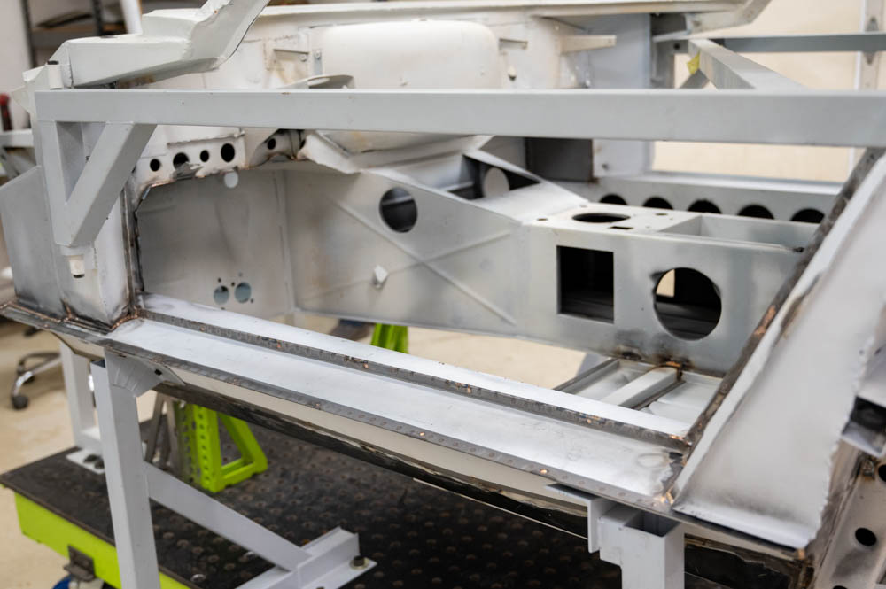
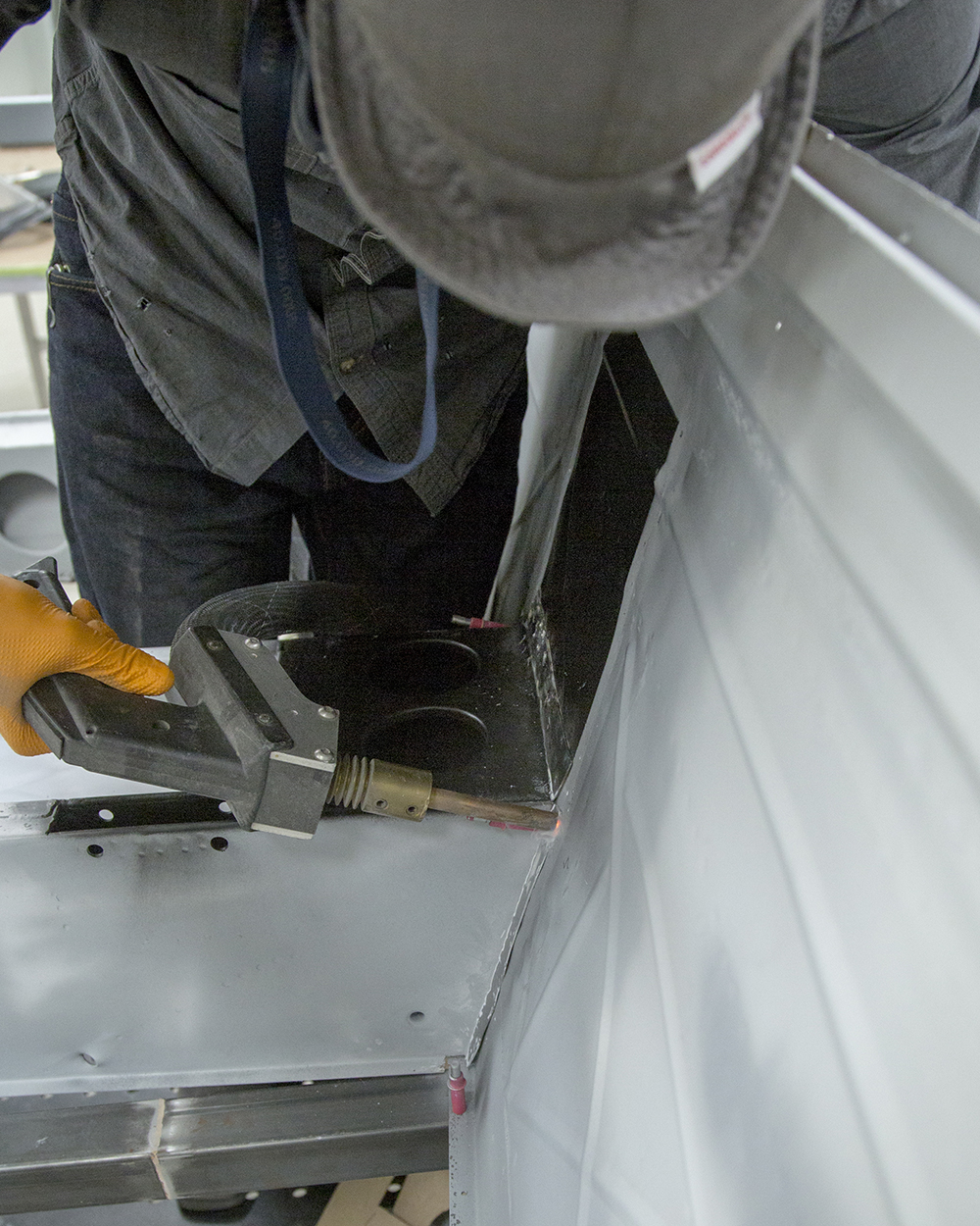
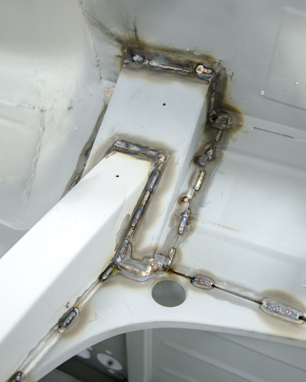
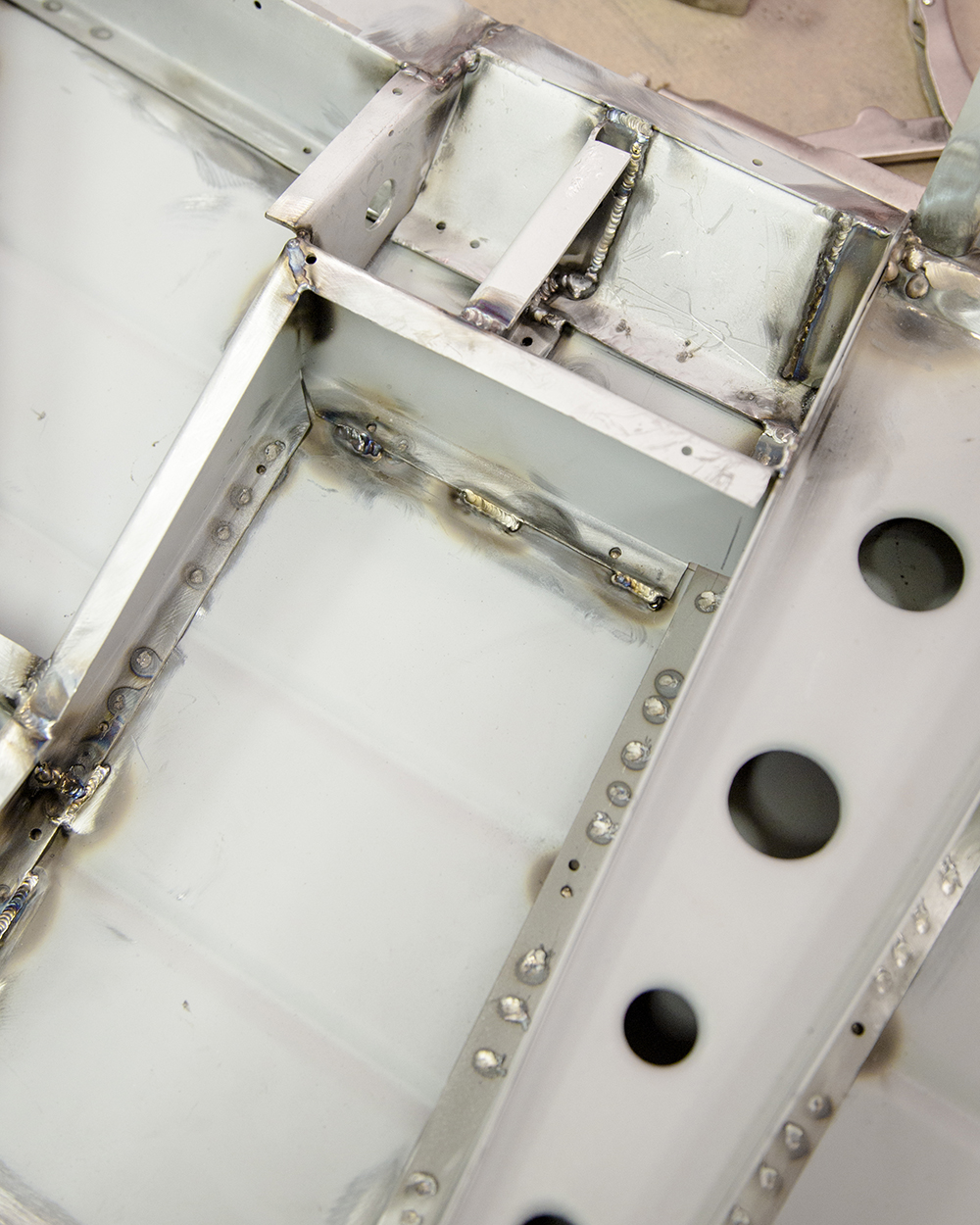
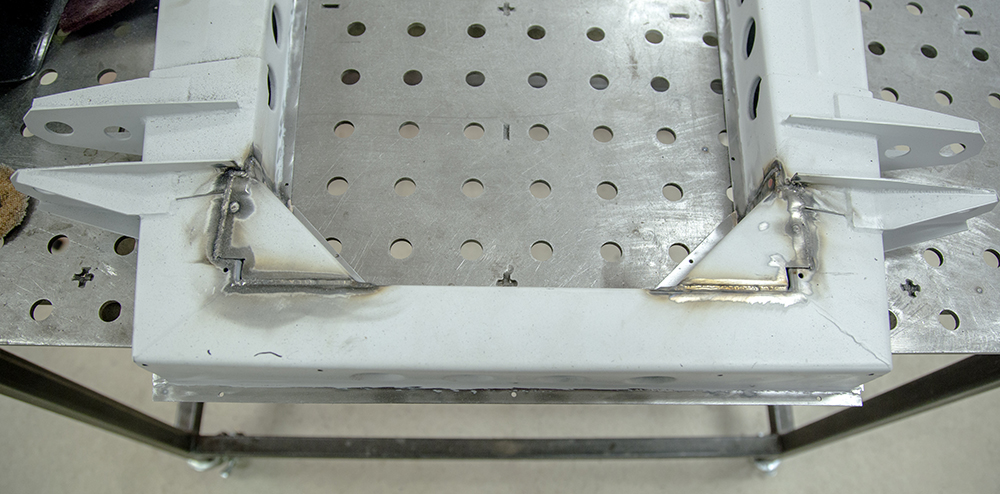
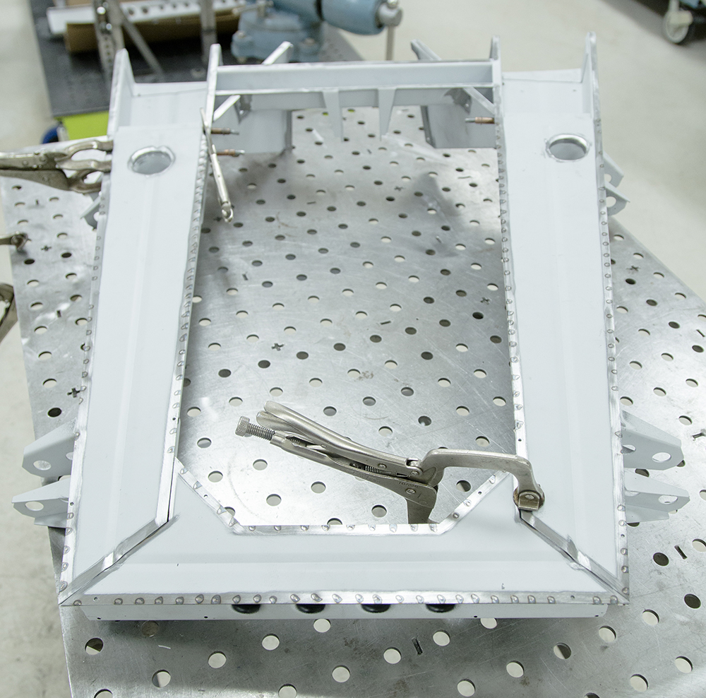
Right hand floor pan now welded in position
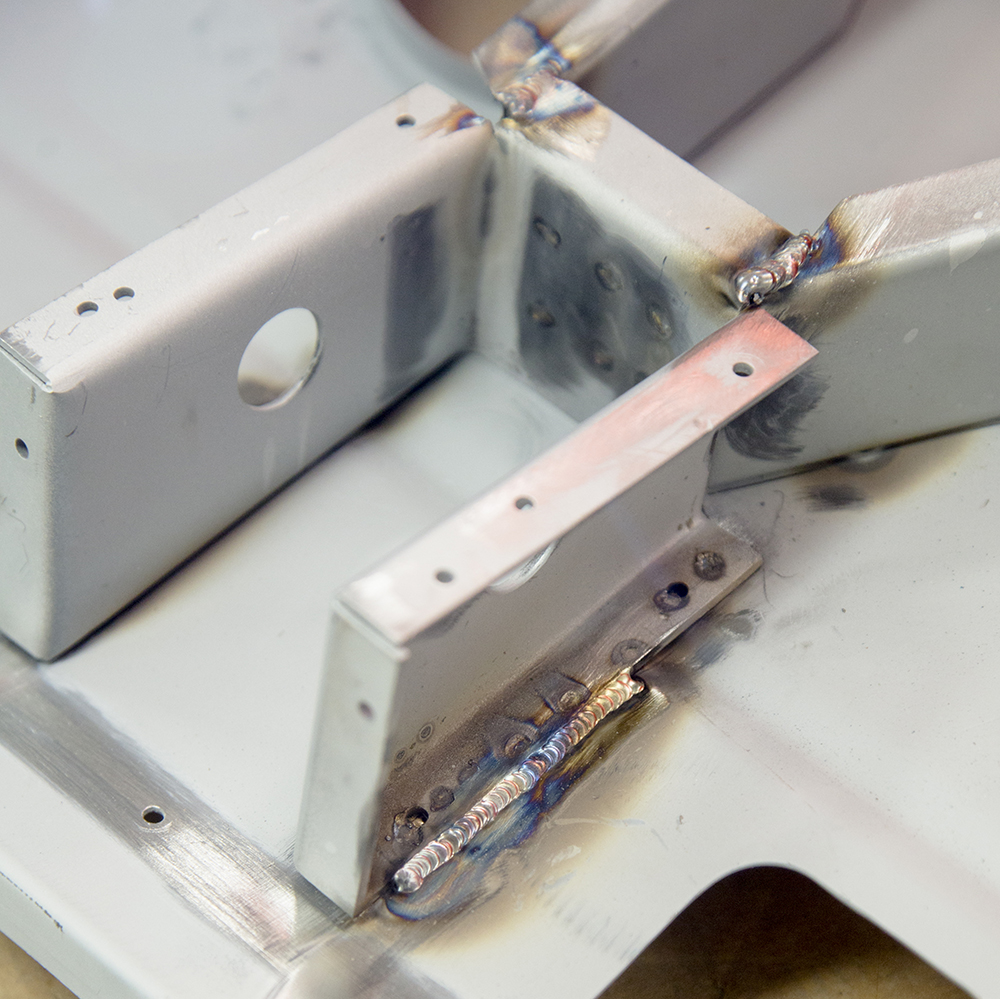
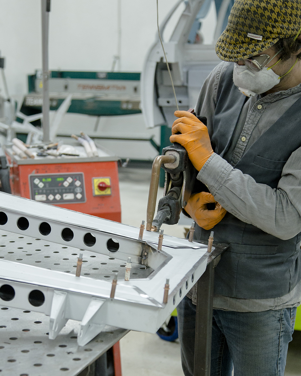
Spot welding the A pillar to the cowl panel
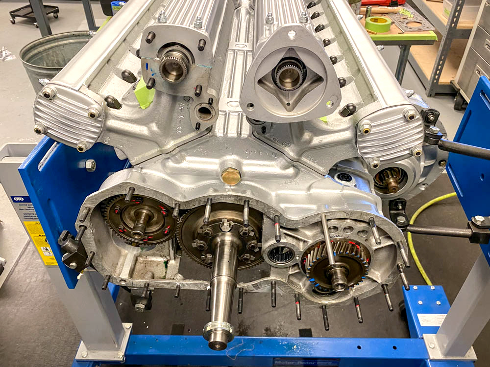
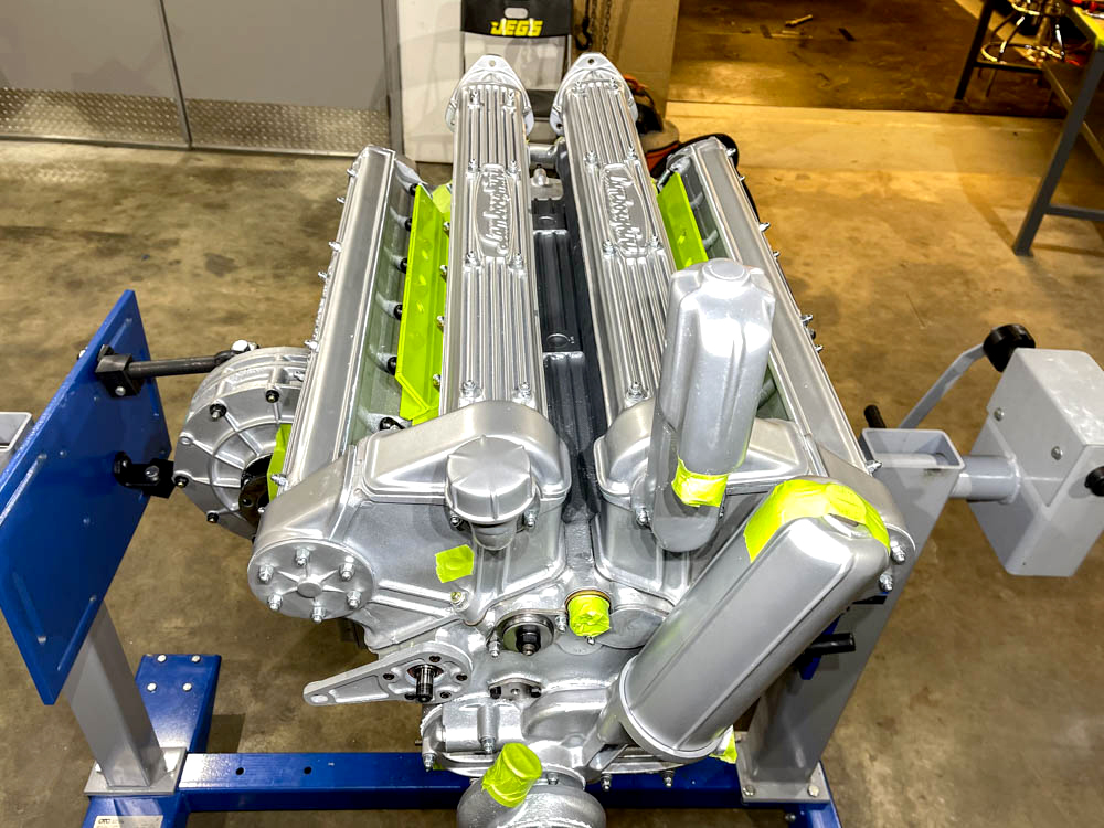
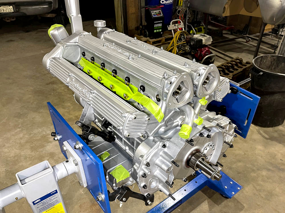
Putting the finishing touches to the engine
and transaxle rebuild
Update
report - July
16, 2021
Update report
- July 9, 2021
Update report
- July 6, 2021
Update report
- June 29,
2021
Update report
- June 24,
2021
Update report
- June 9, 2021
Update report
- June 2, 2021
Update report
- April 26,
2021
Update report
- April 22,
2021
Update report
- April 8,
2021
Update report
- March 29,
2021
Update report
- March 17,
2021
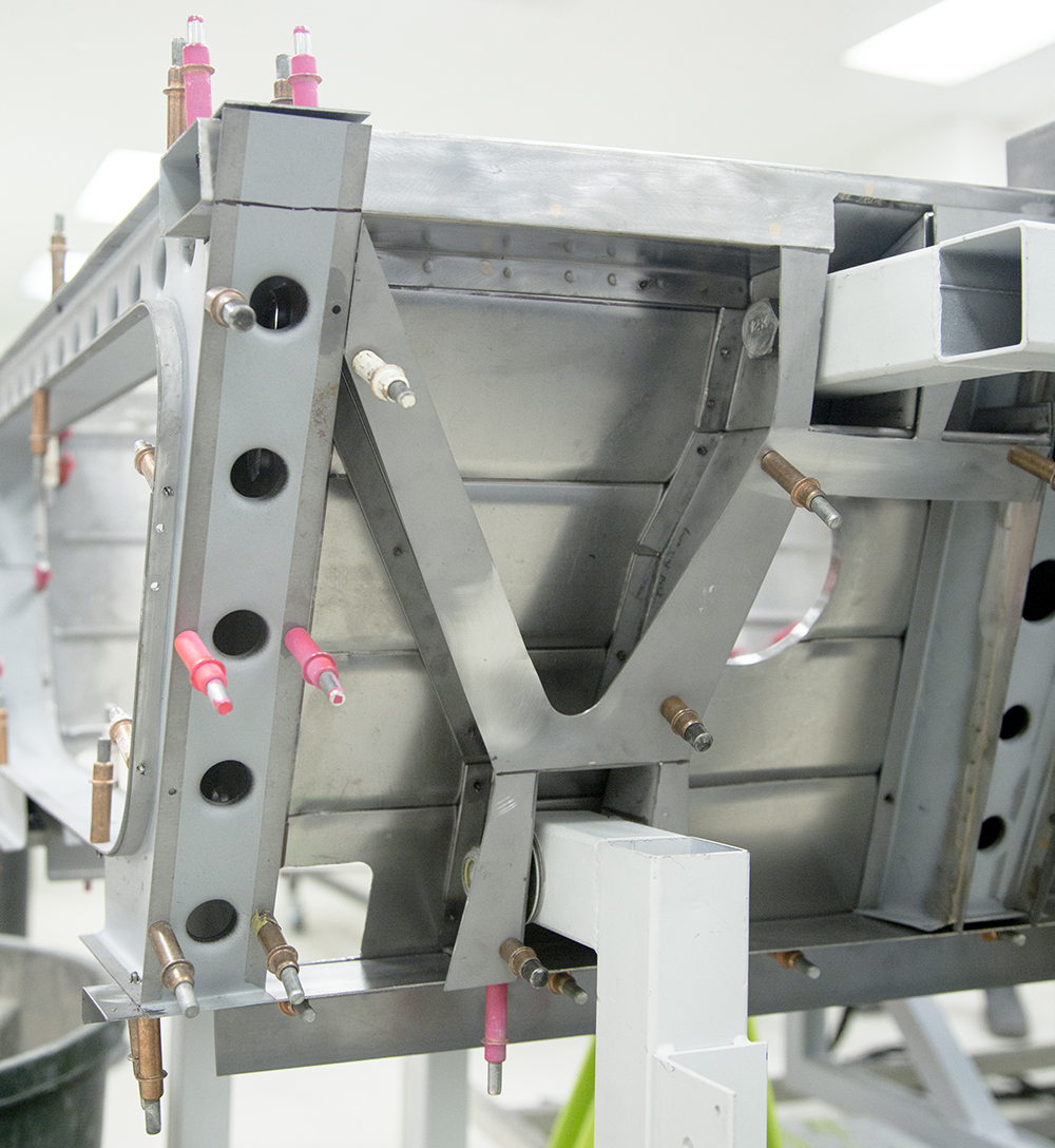
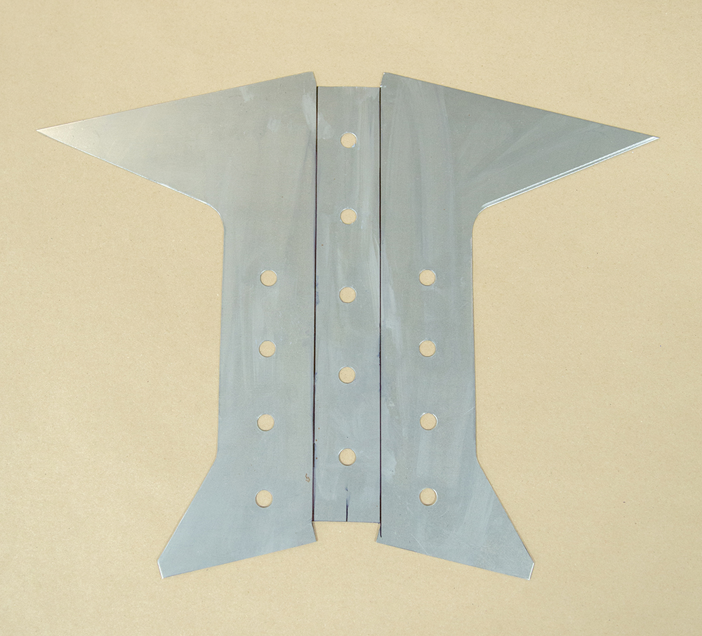
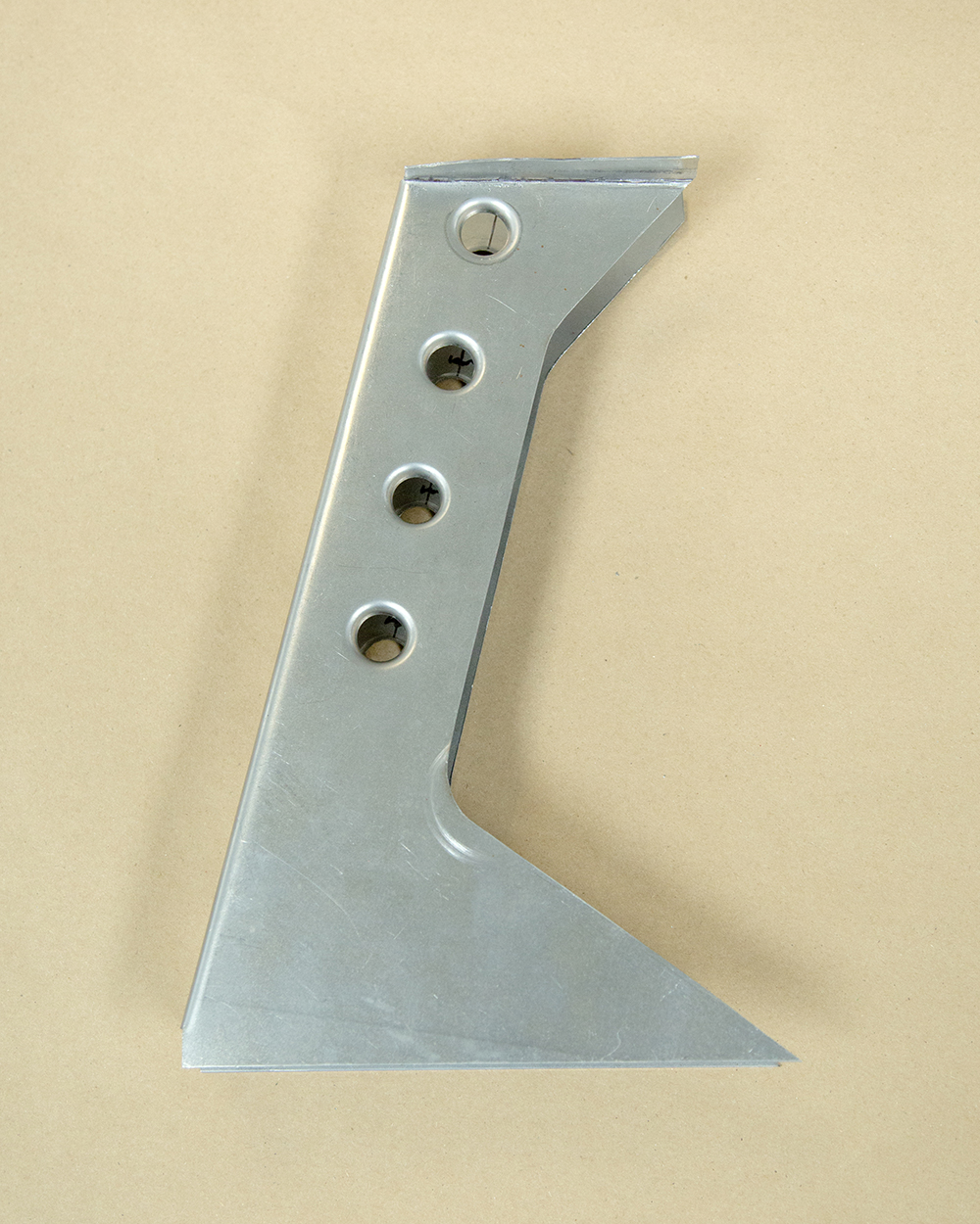
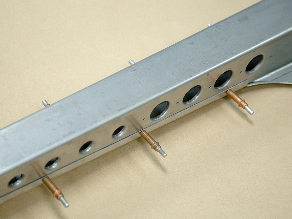
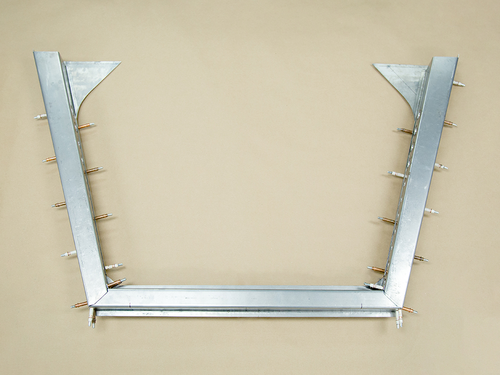
Update report
- March 8,
2021
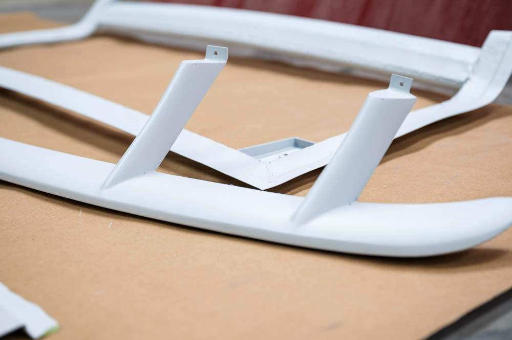
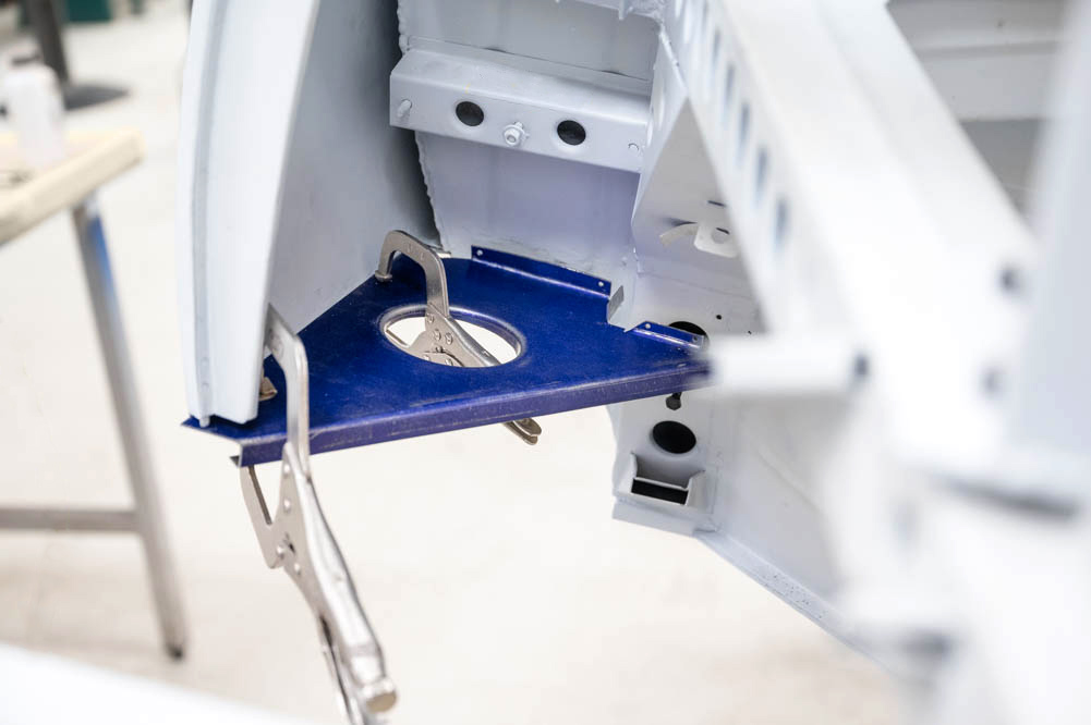
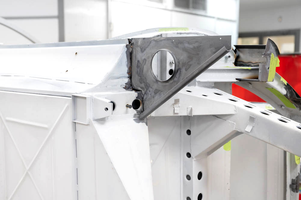
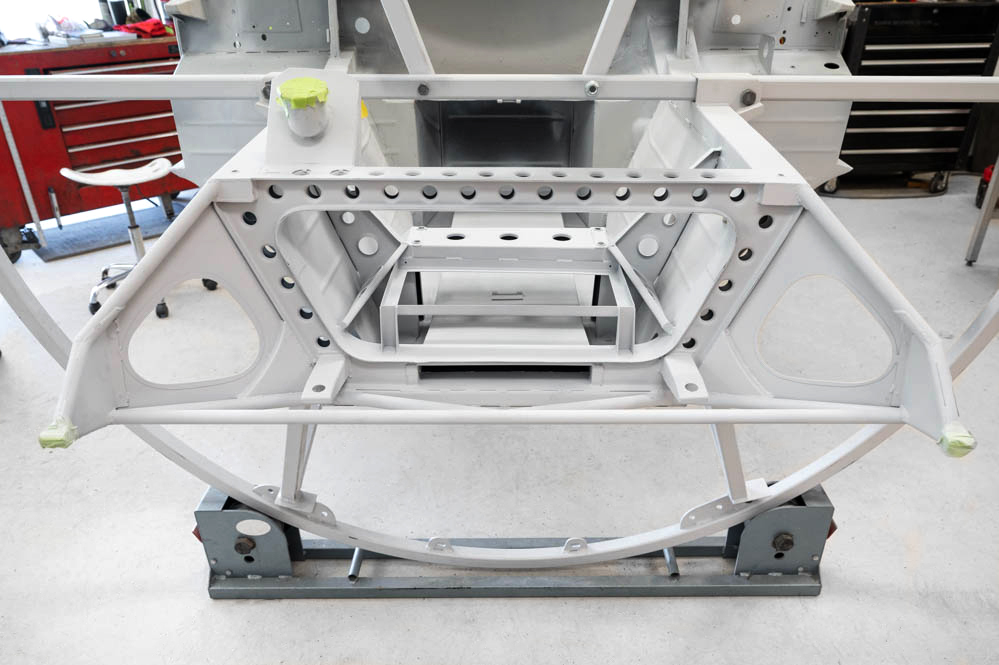
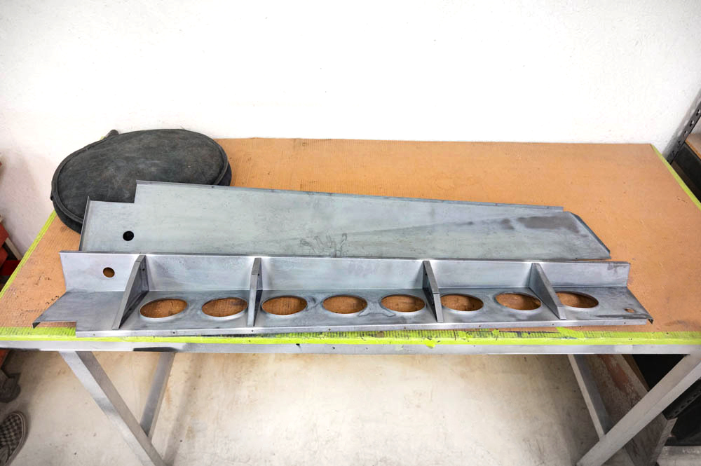
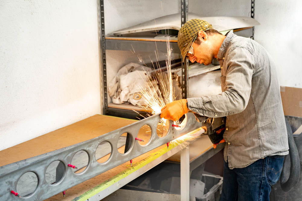
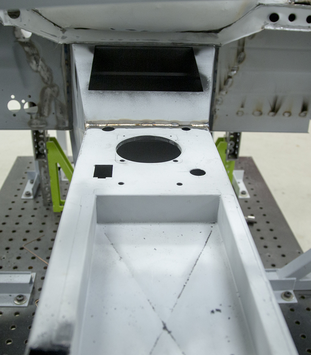
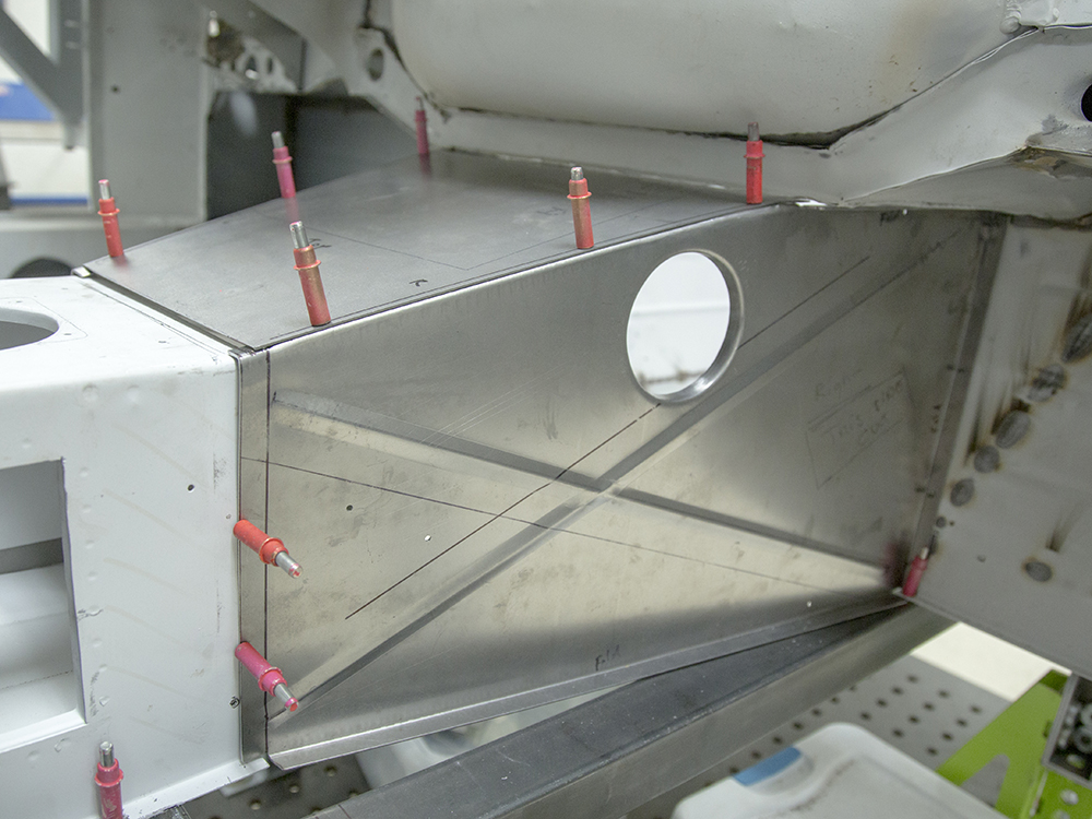
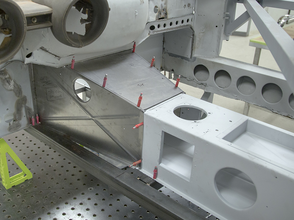
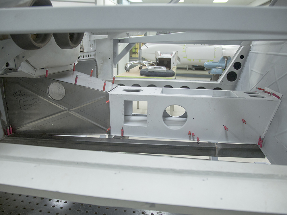
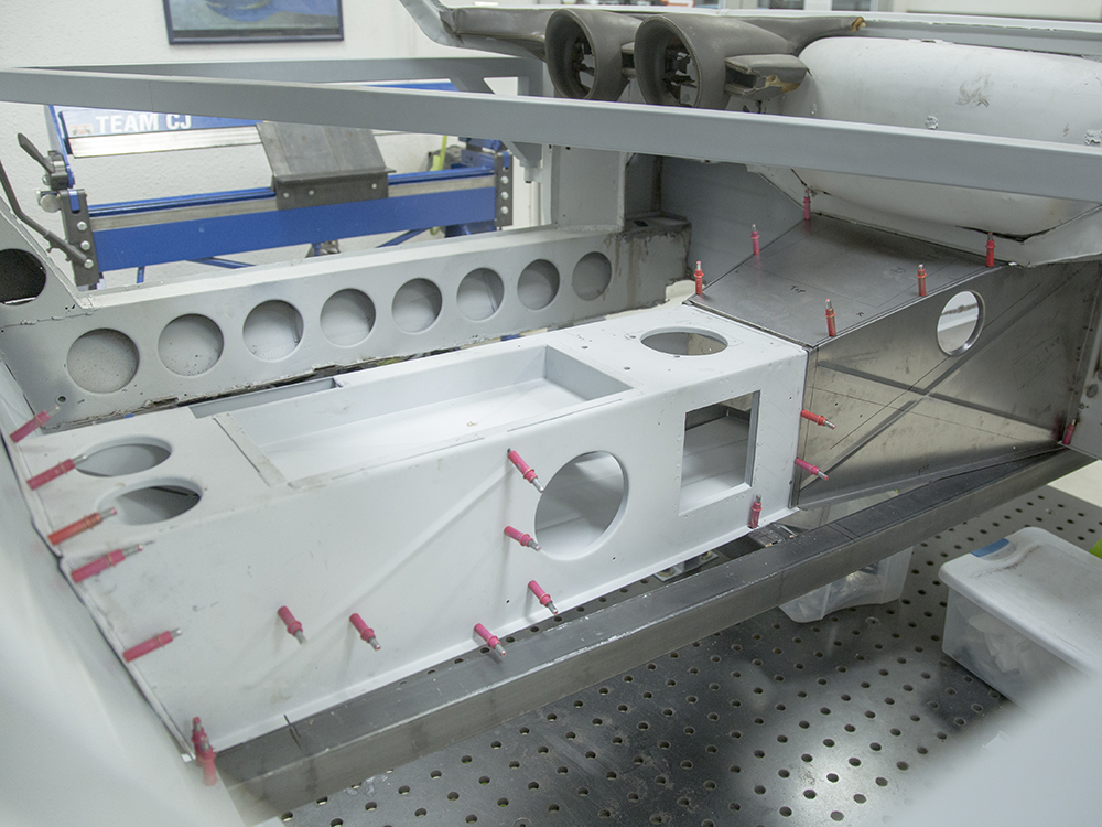
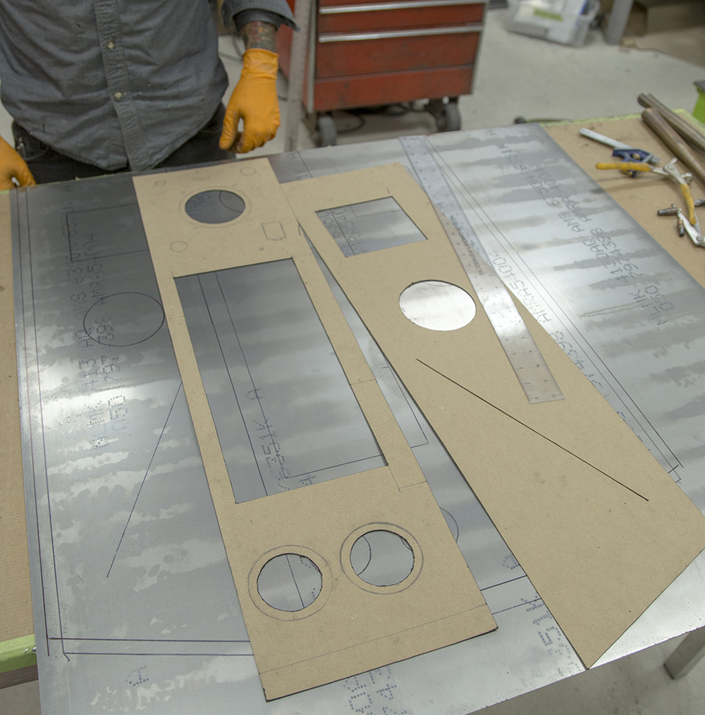
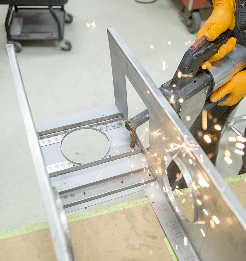
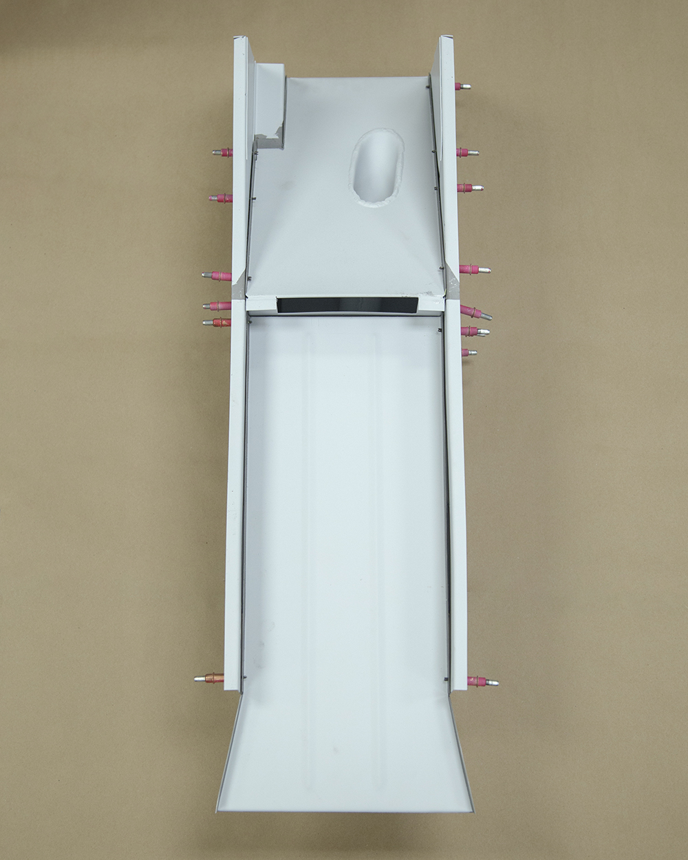
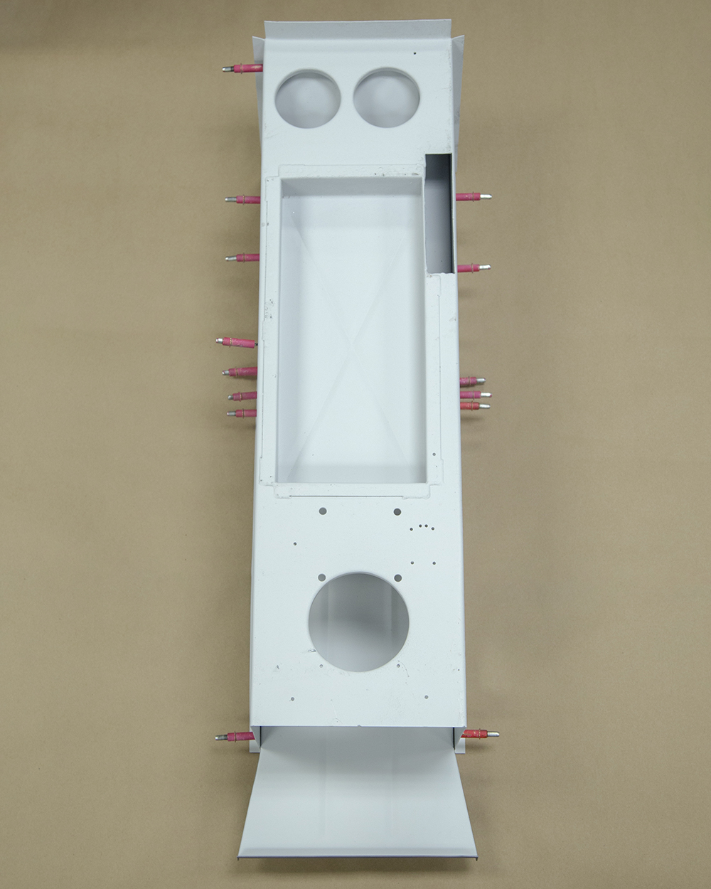
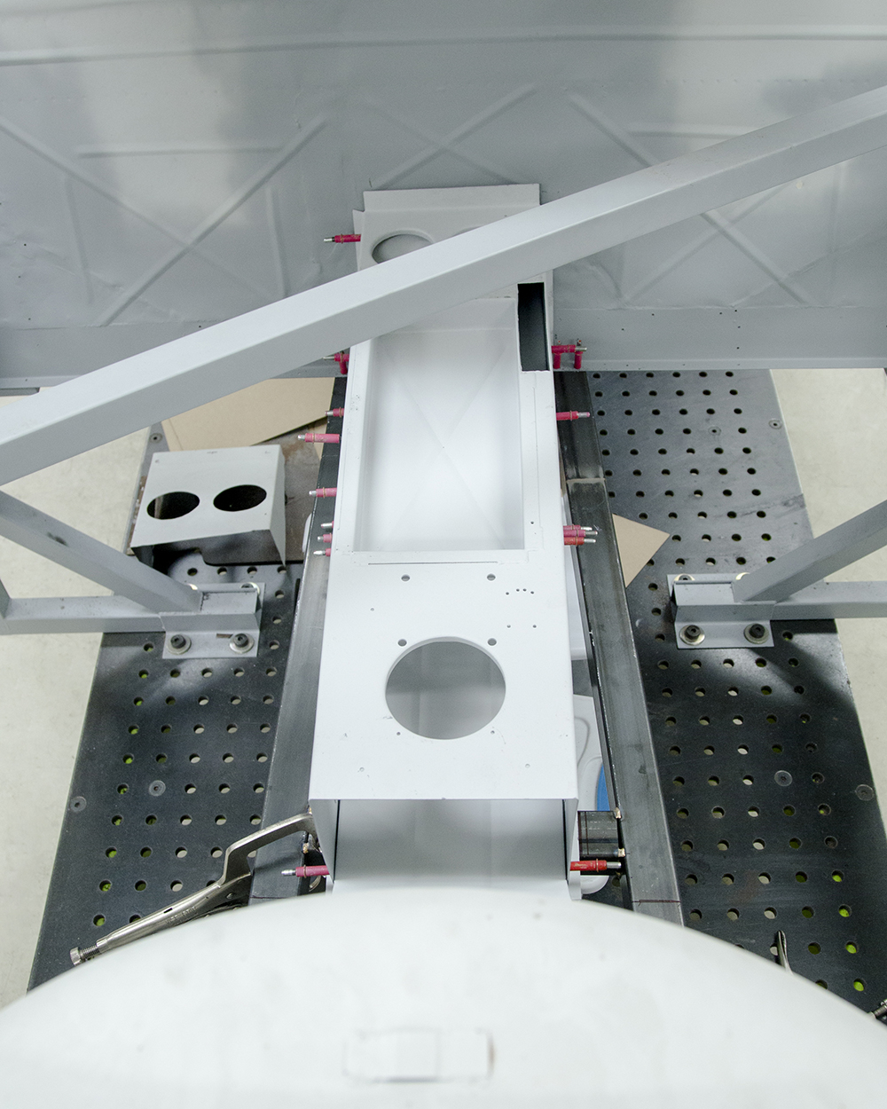
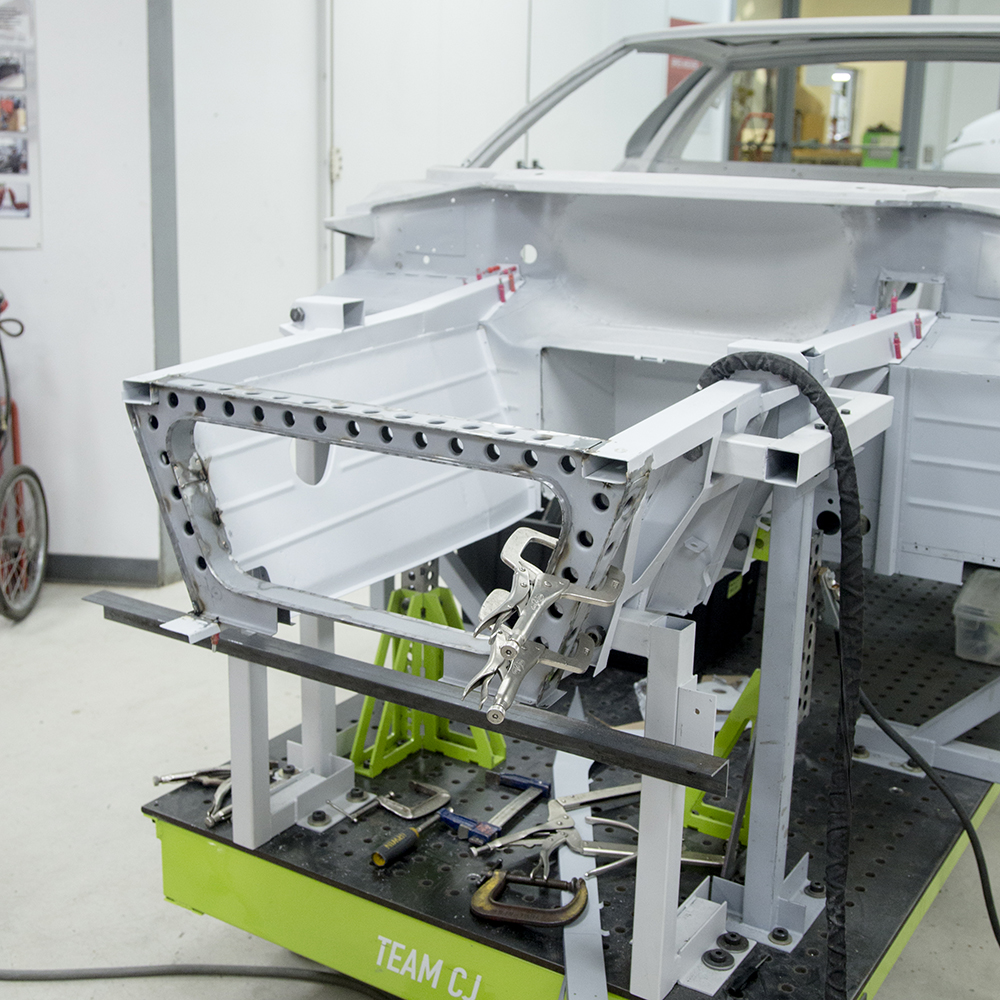
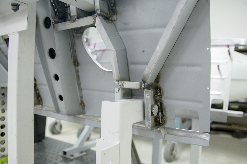
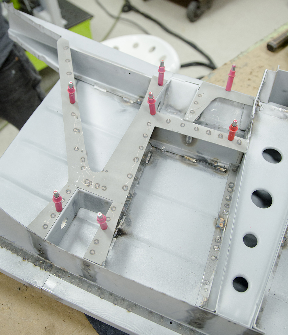
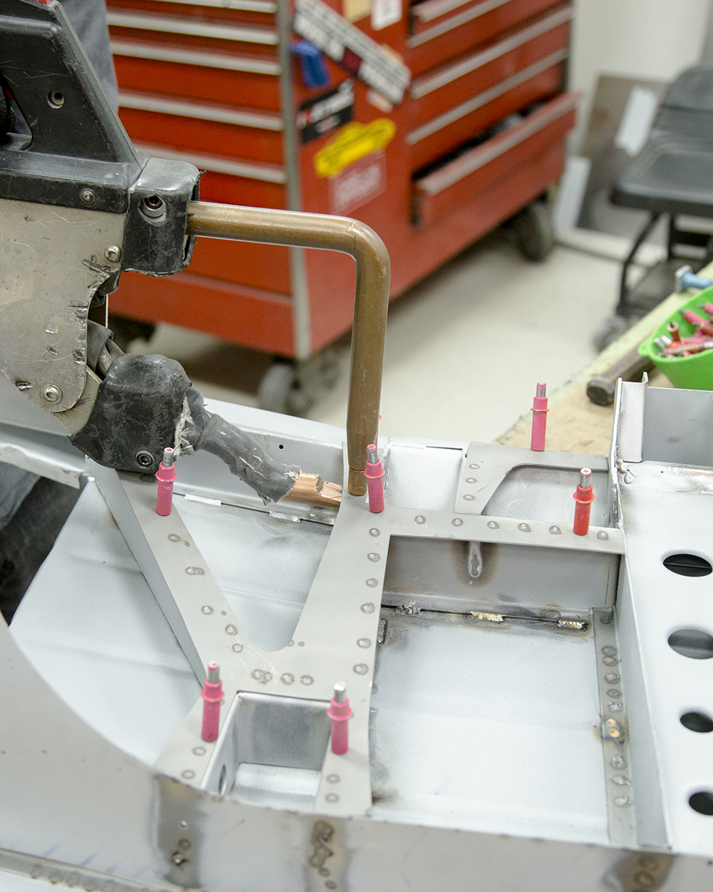
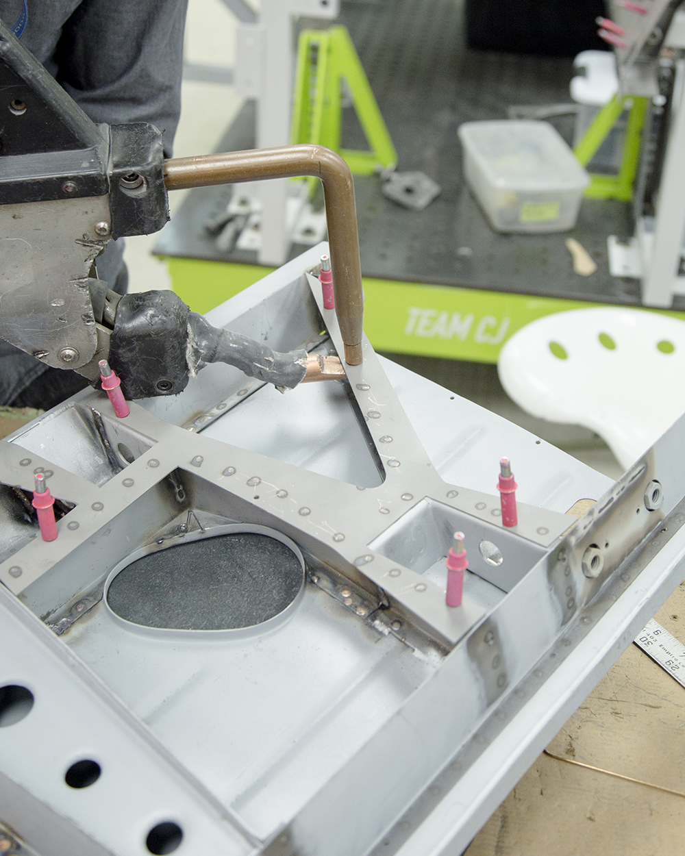
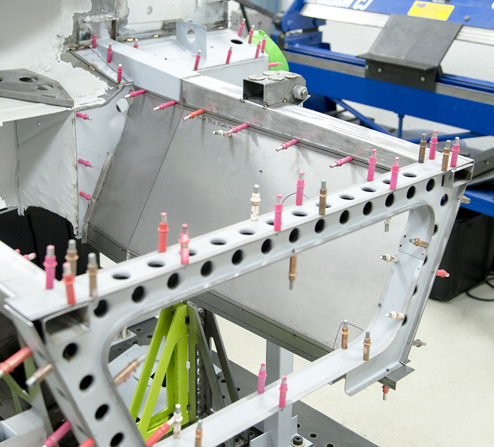
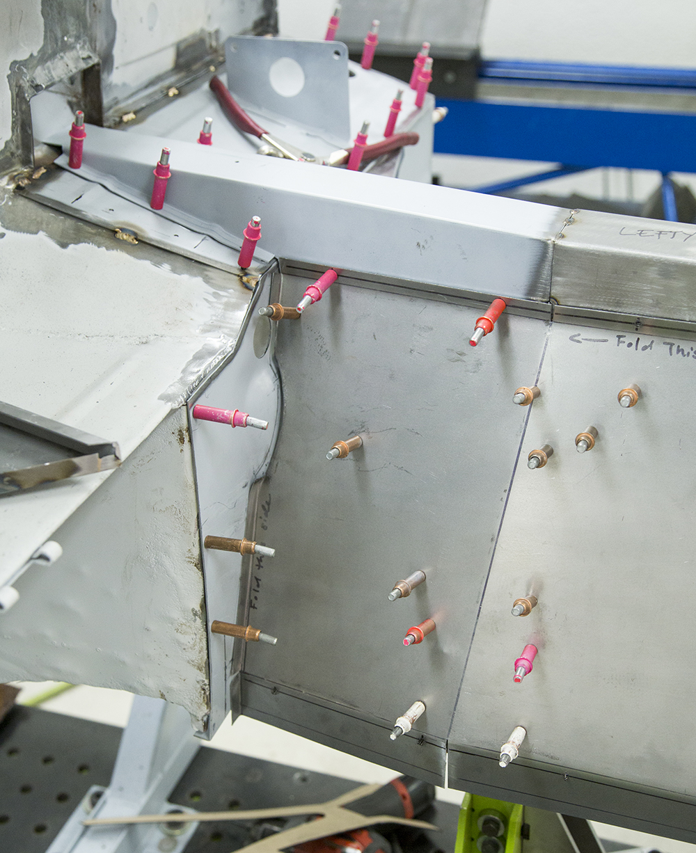
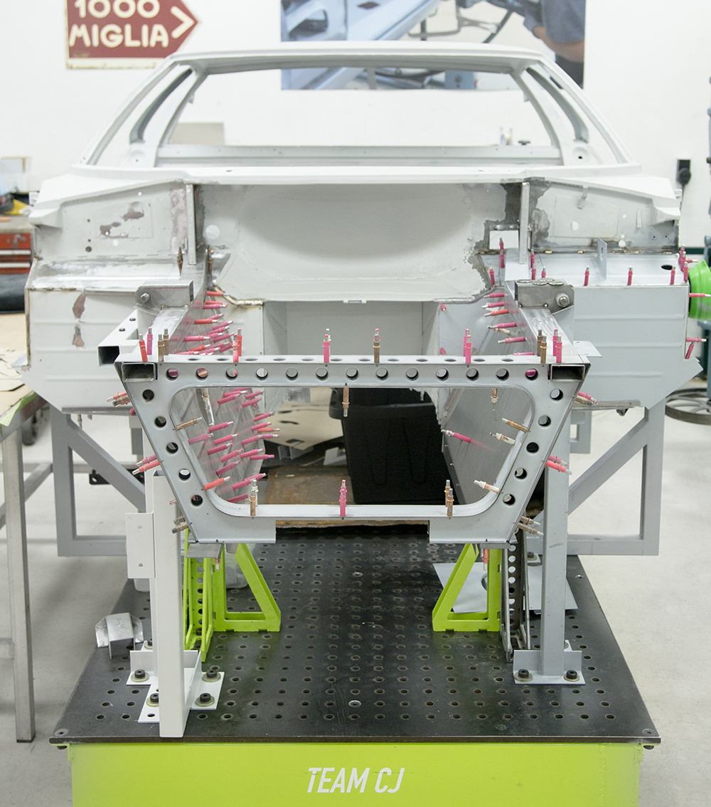
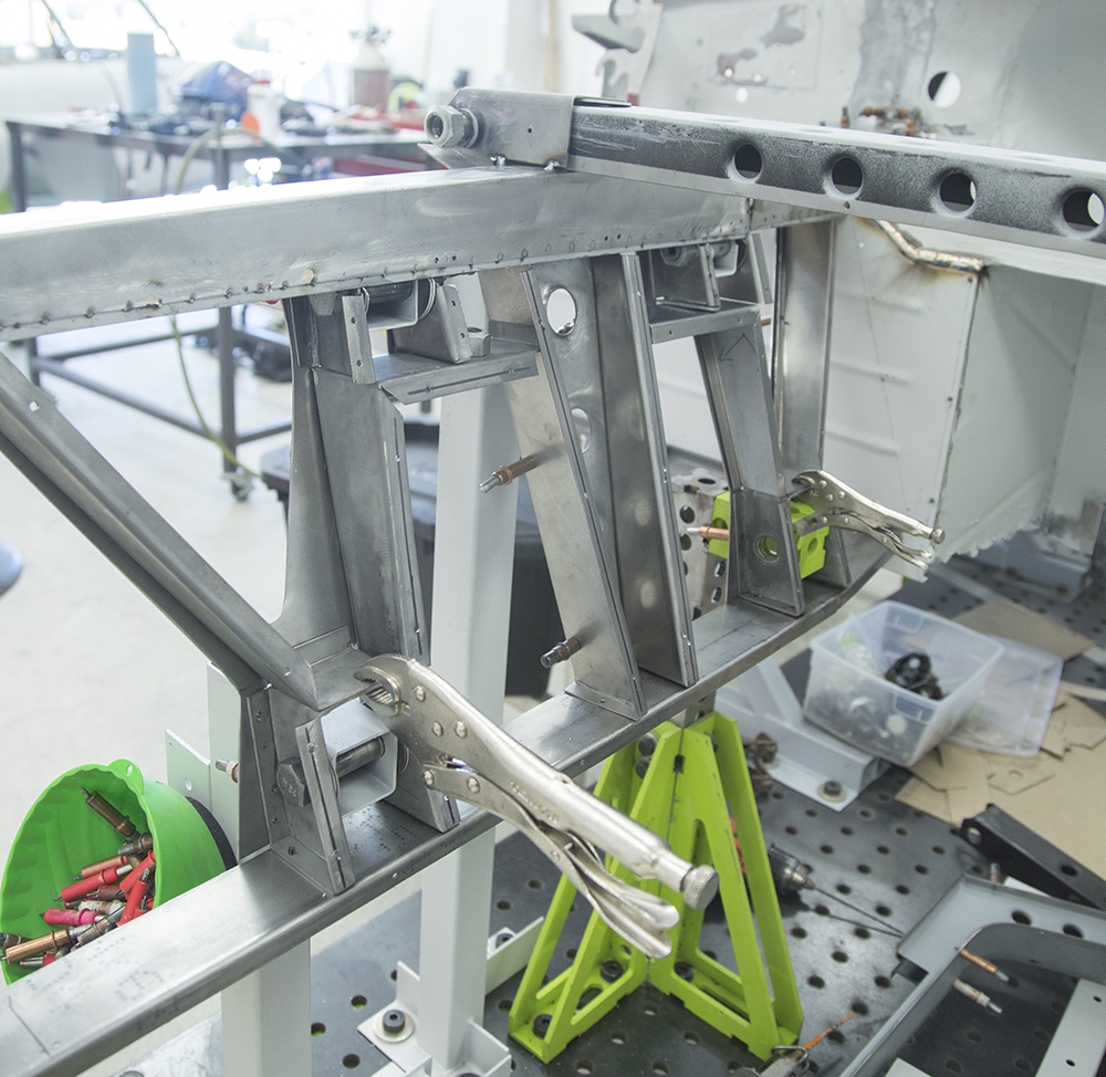
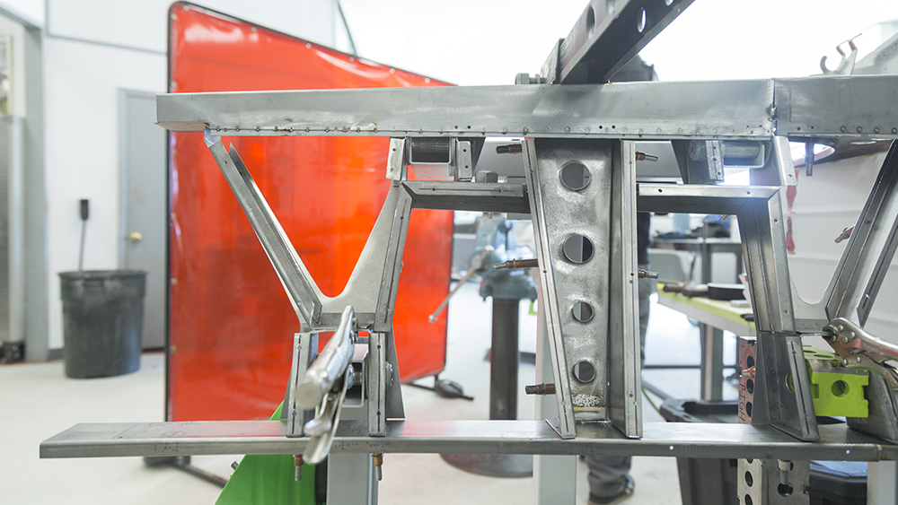
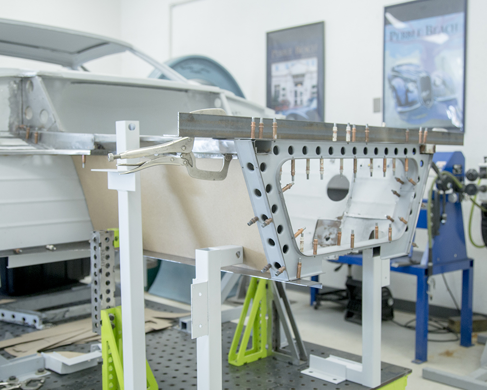
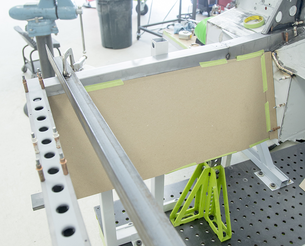
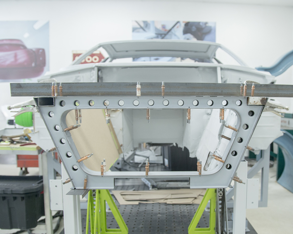
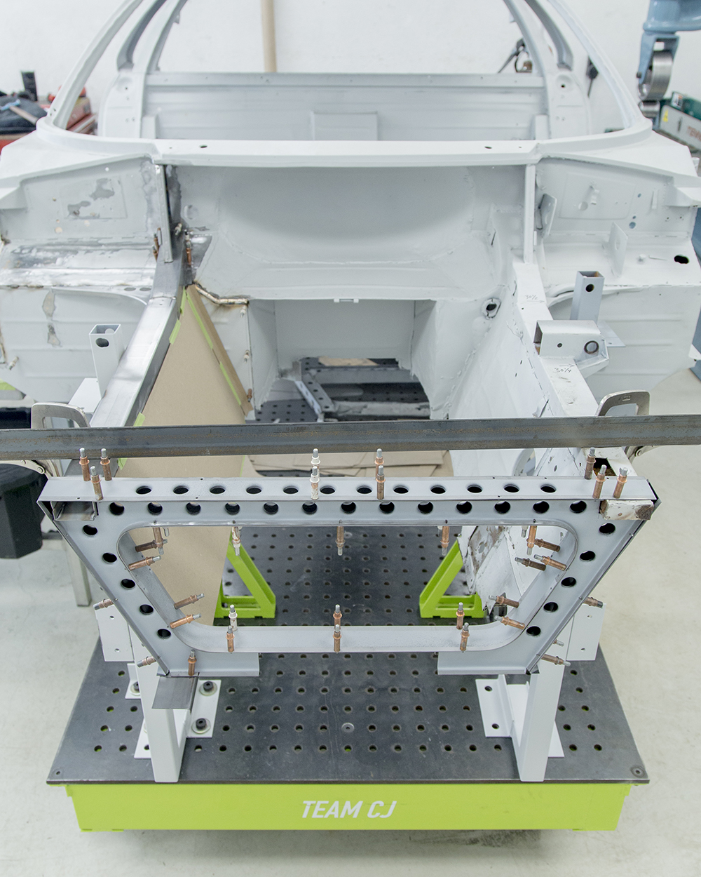
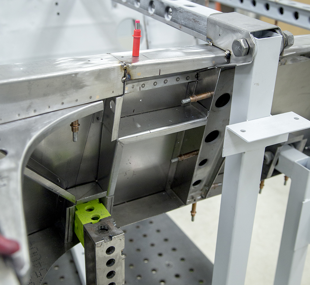
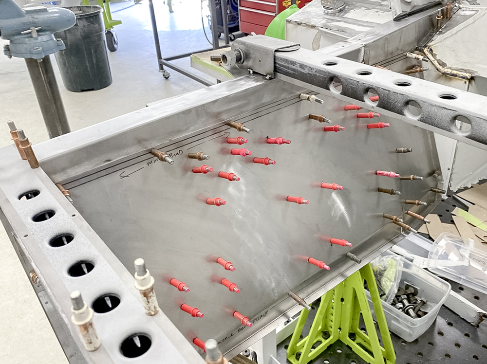
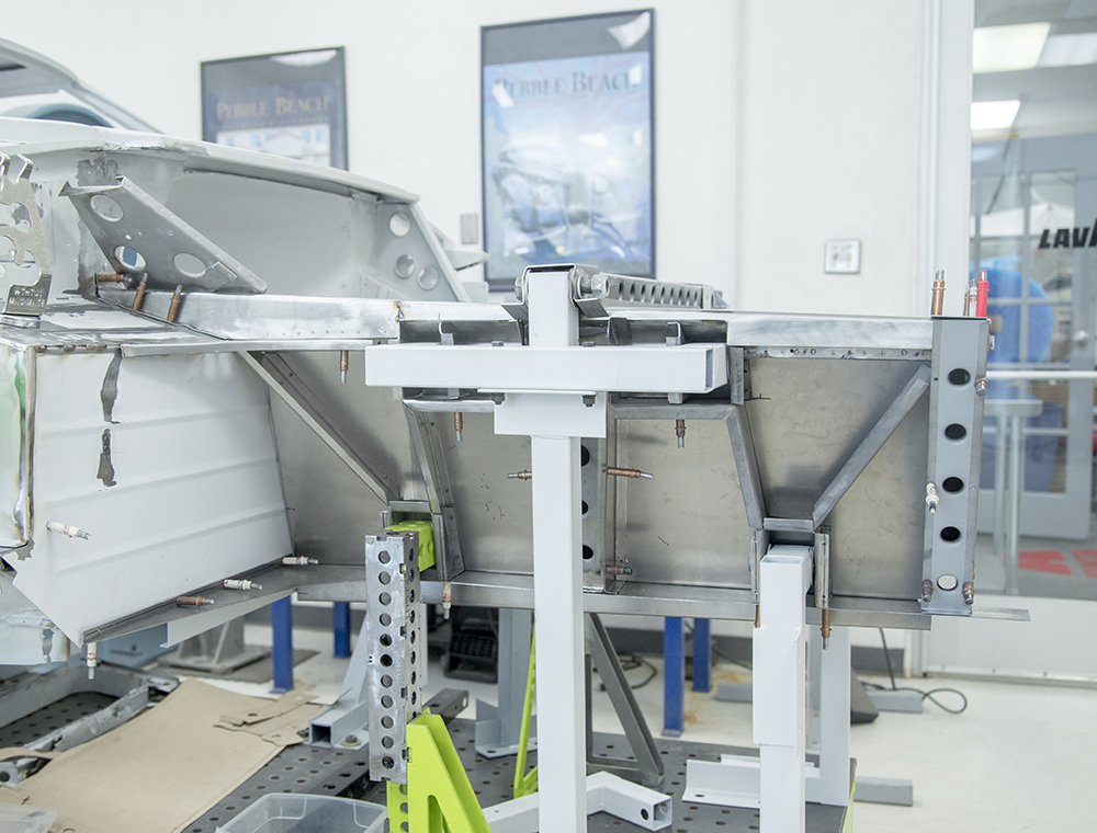
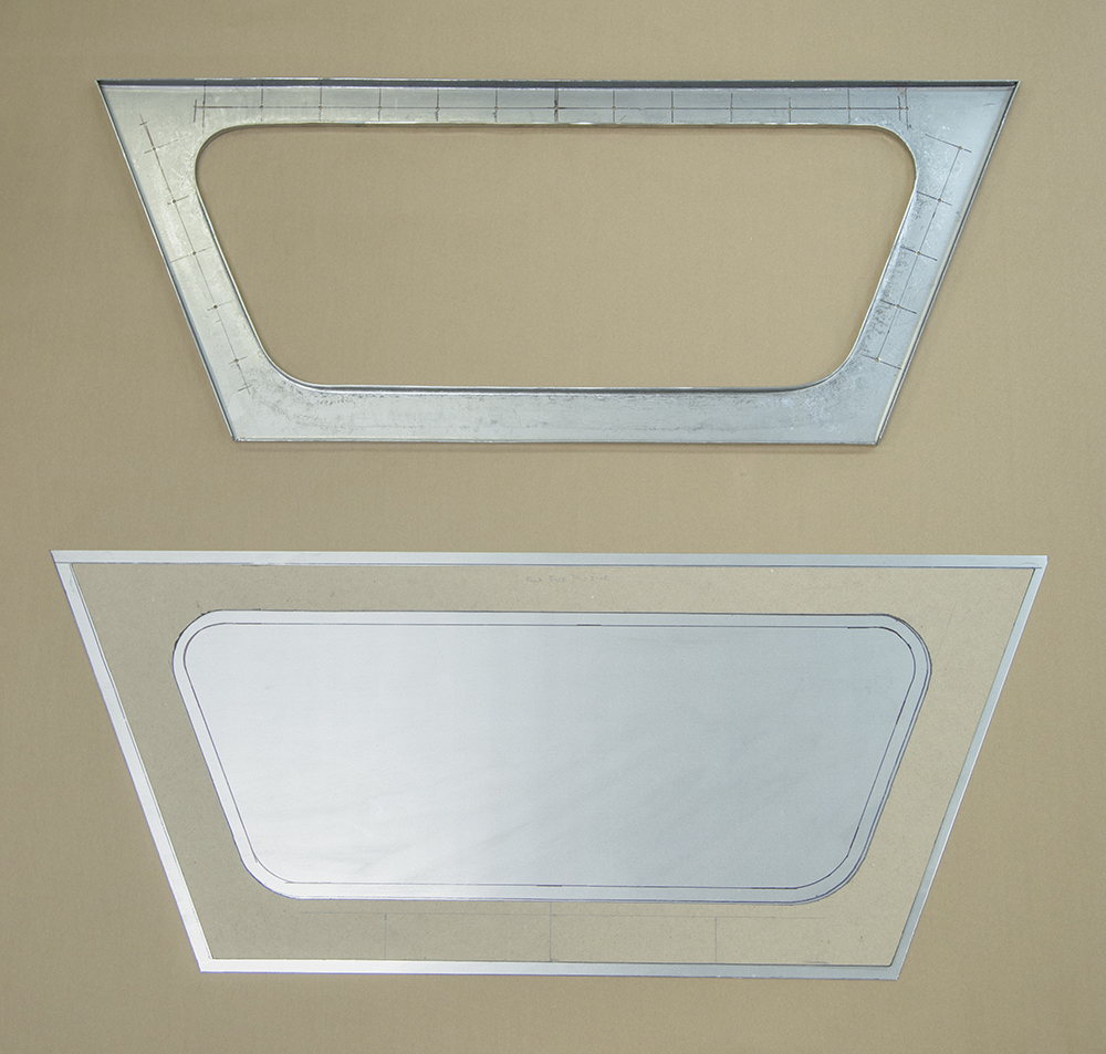
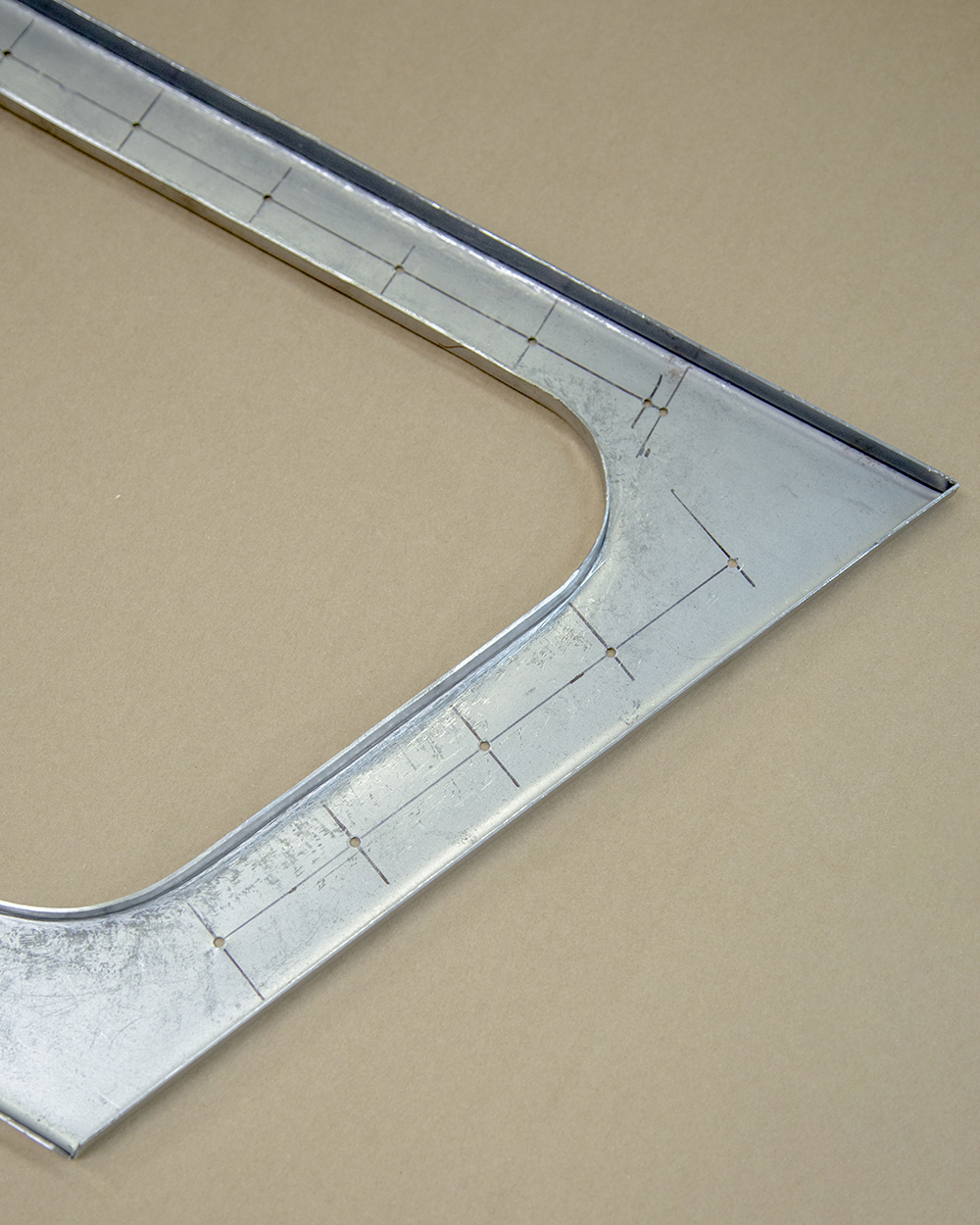
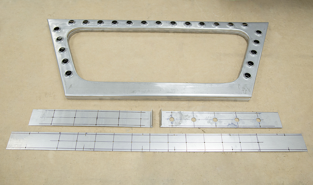
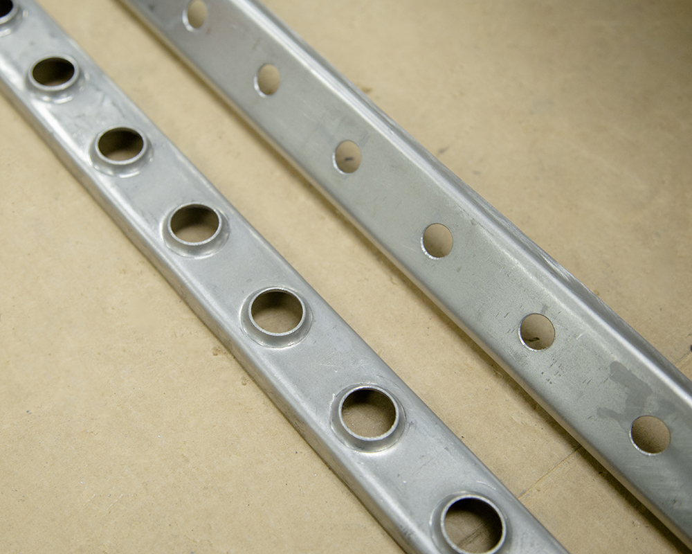
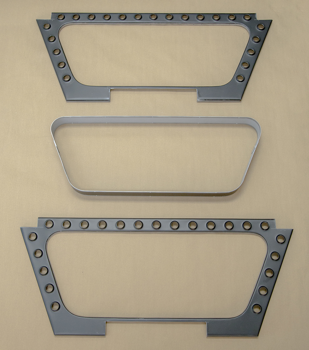
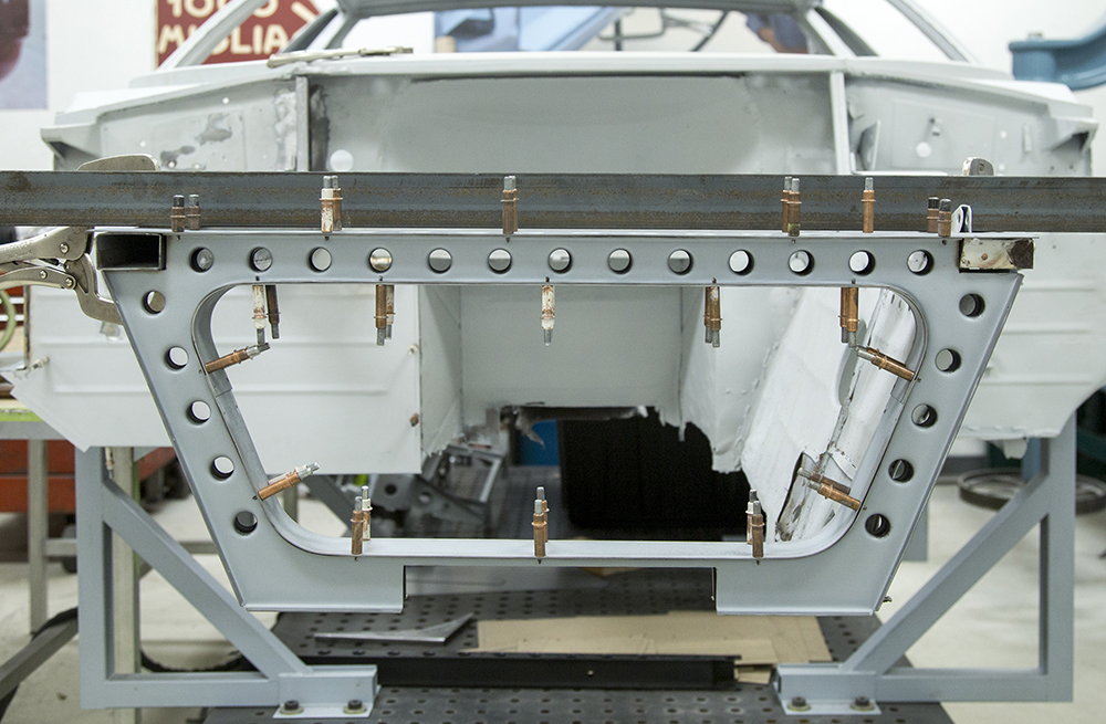
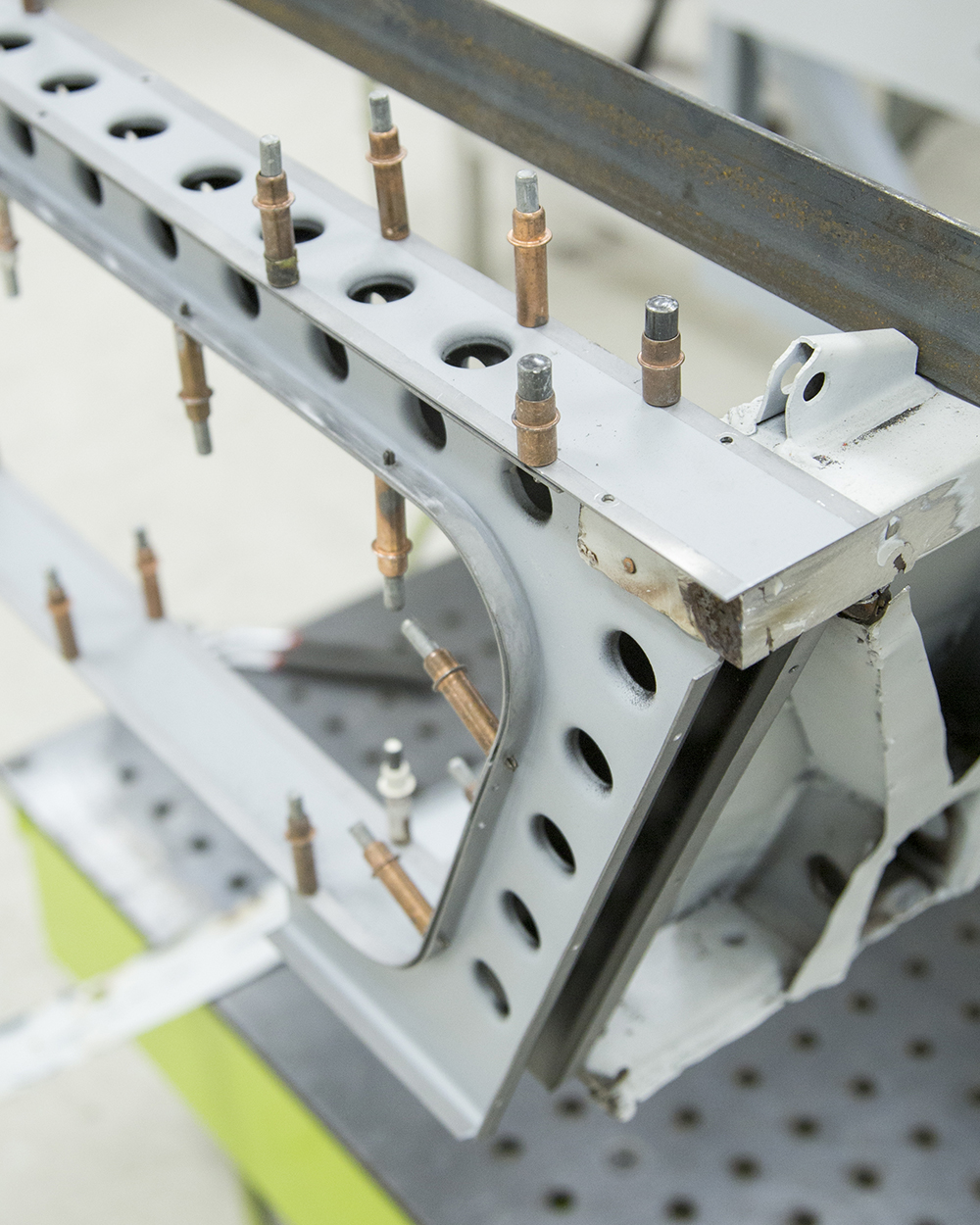
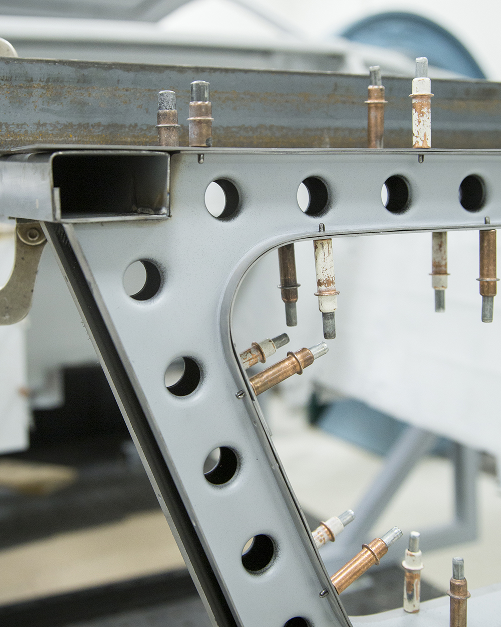
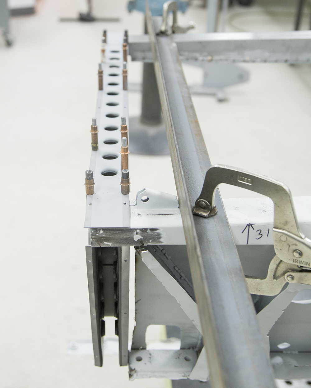
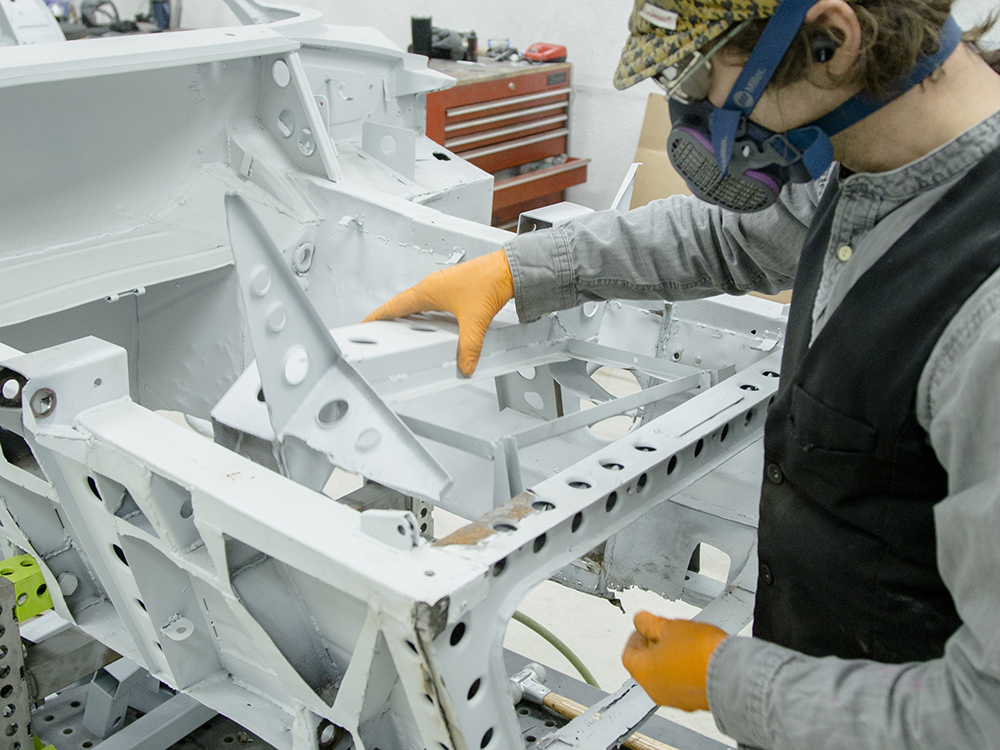
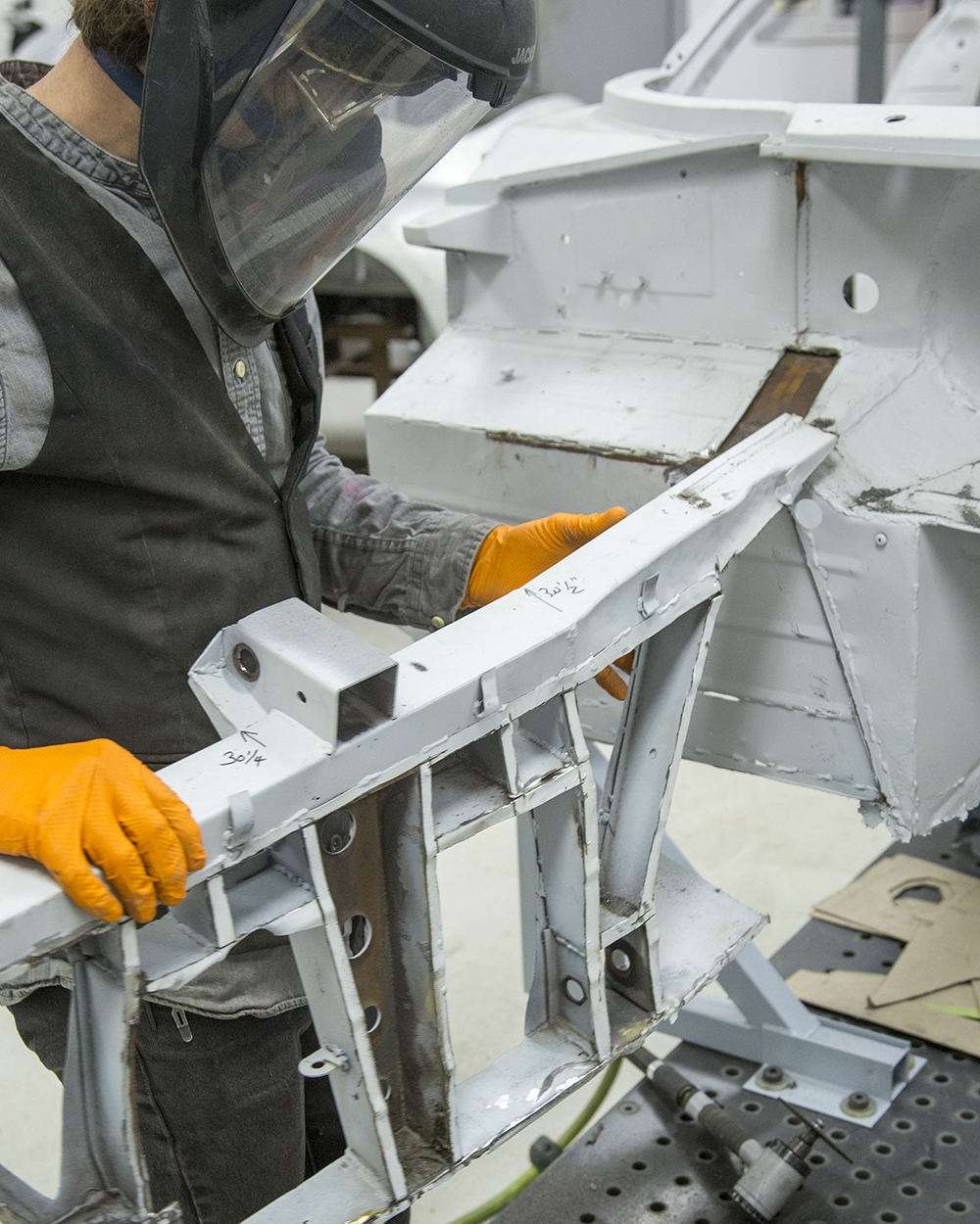
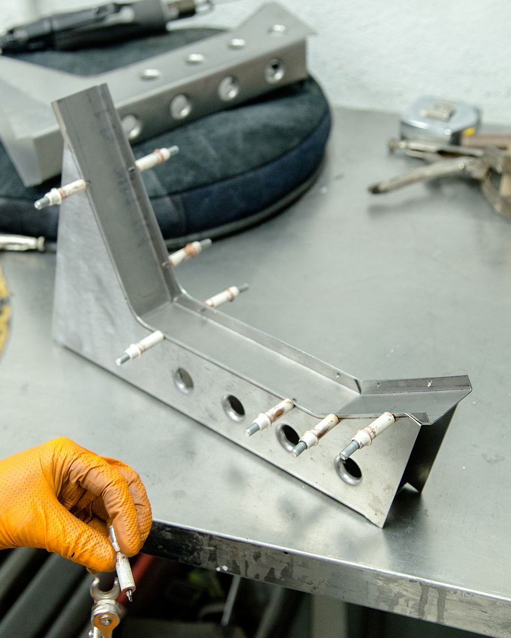
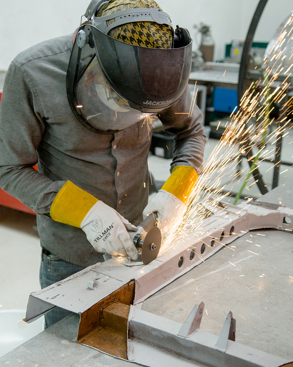
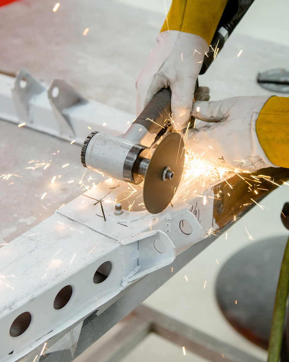
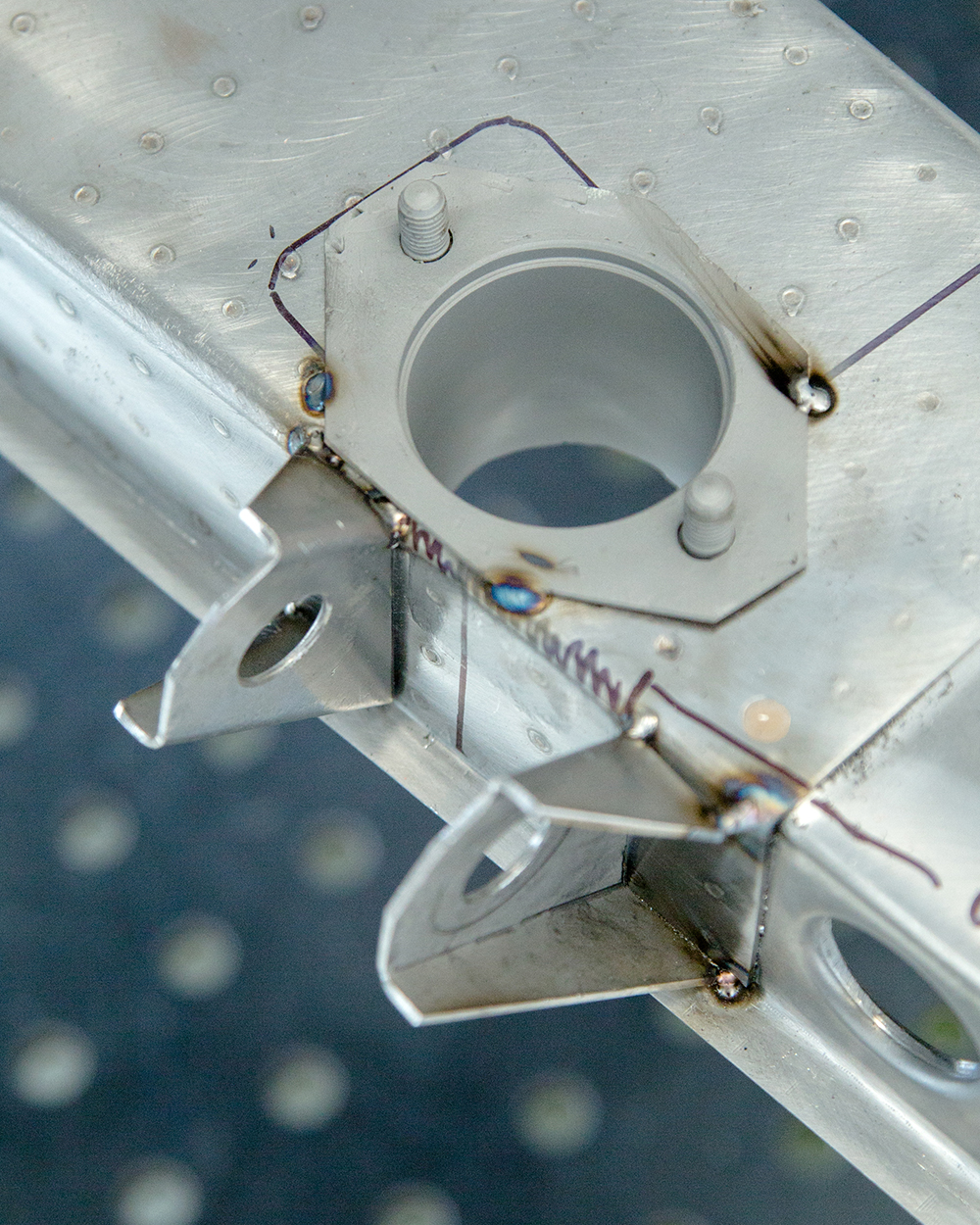
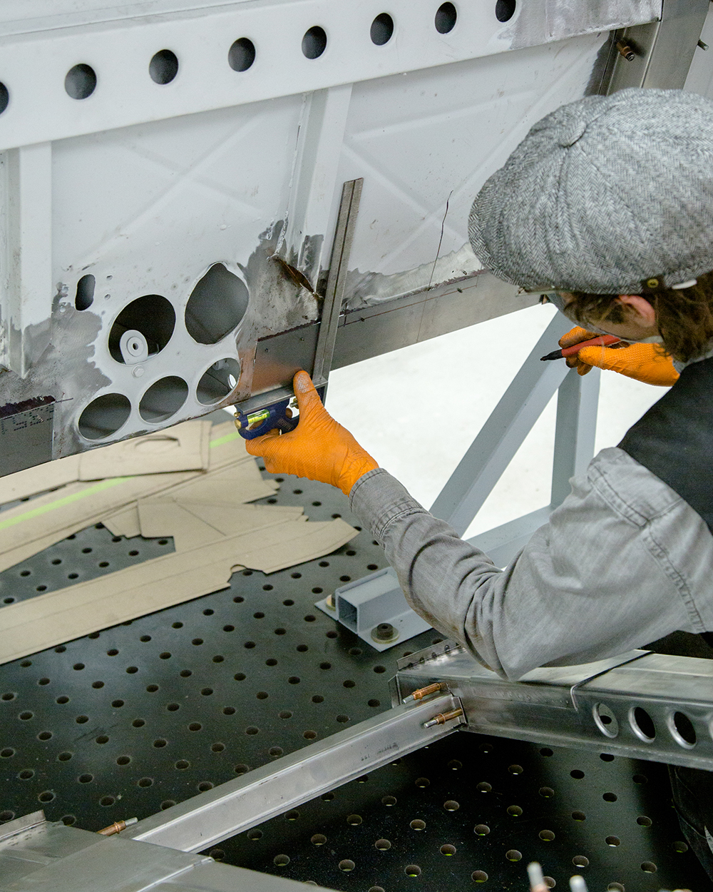
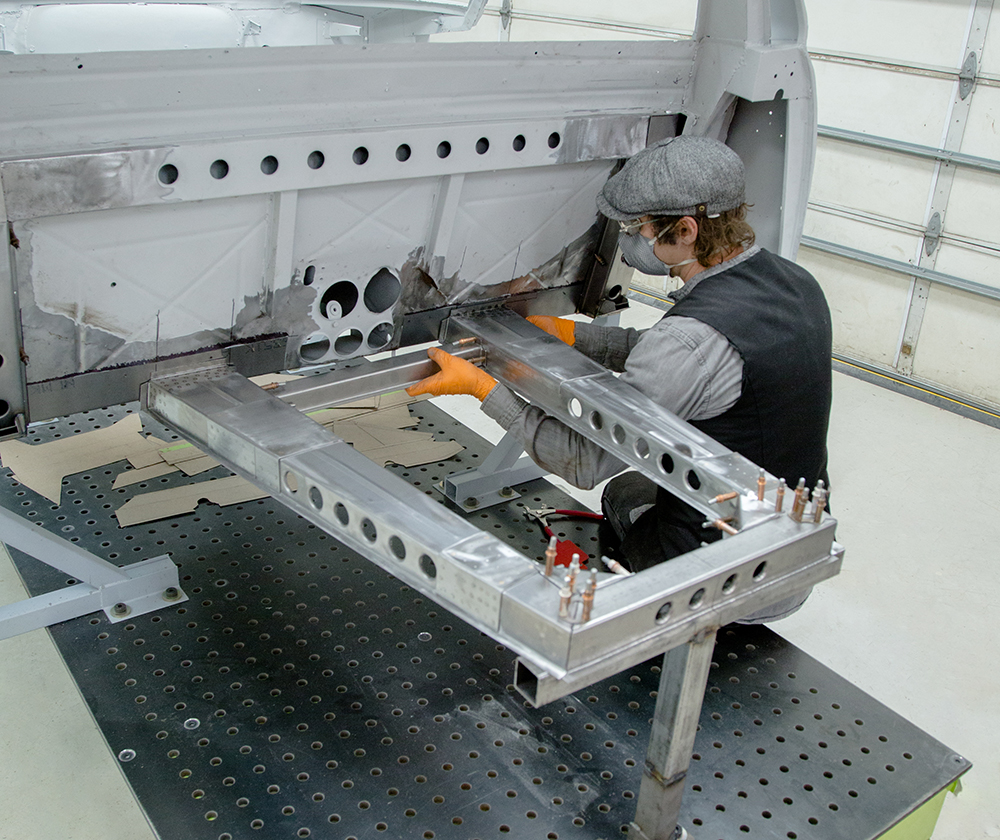
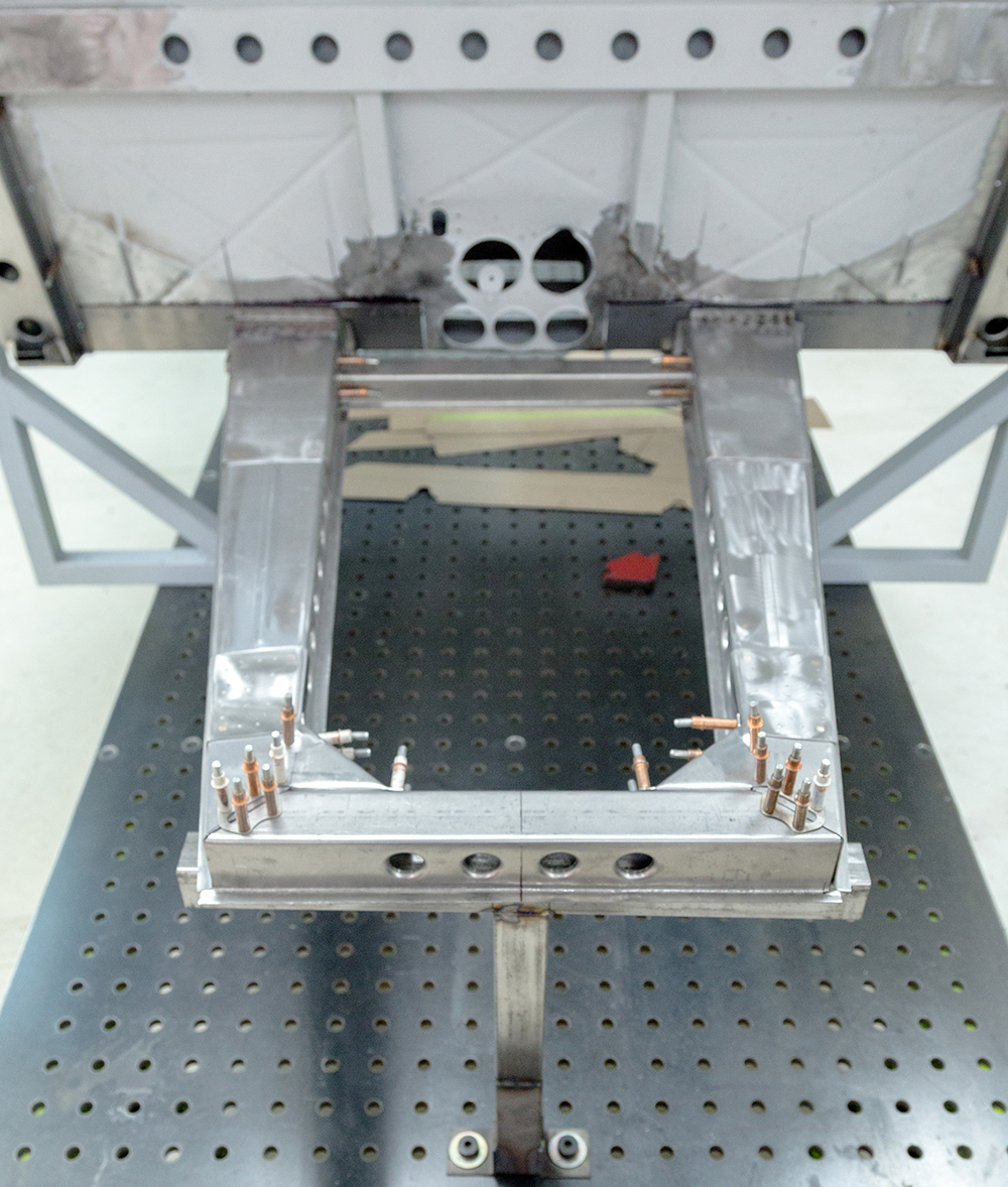
Fabricating the new forward picture
frame and radiator support.
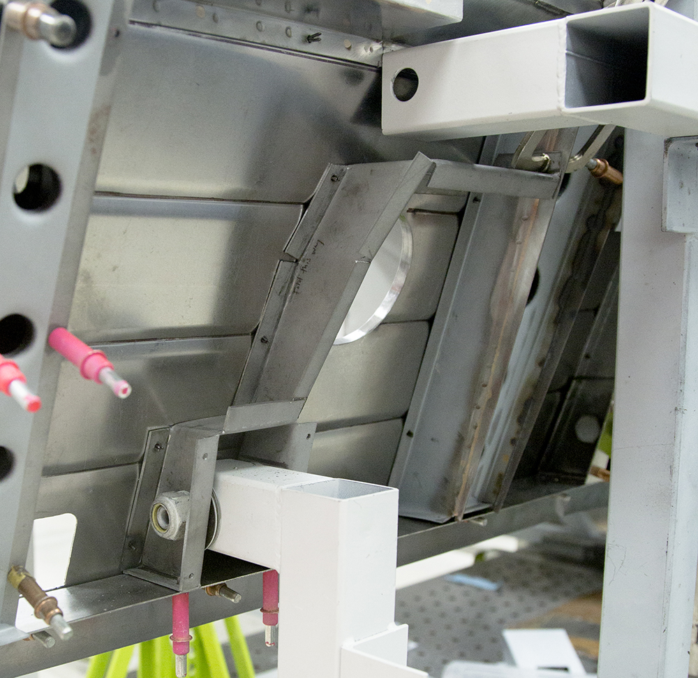
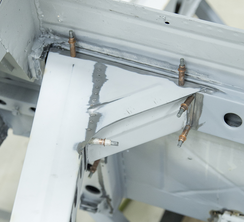
Update report - March 1,
2021
Update report - February
8, 2021
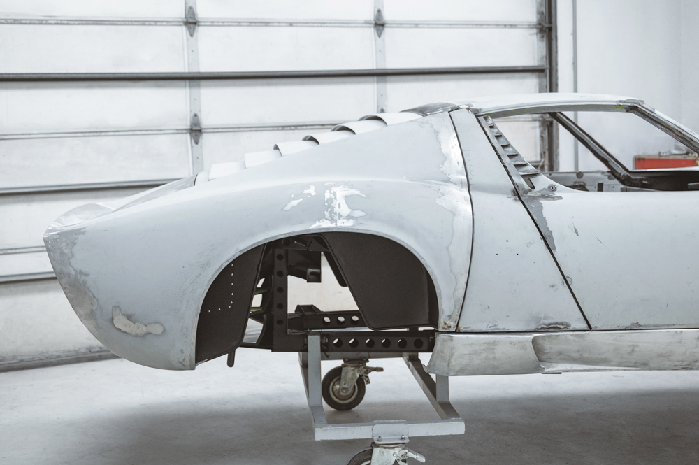
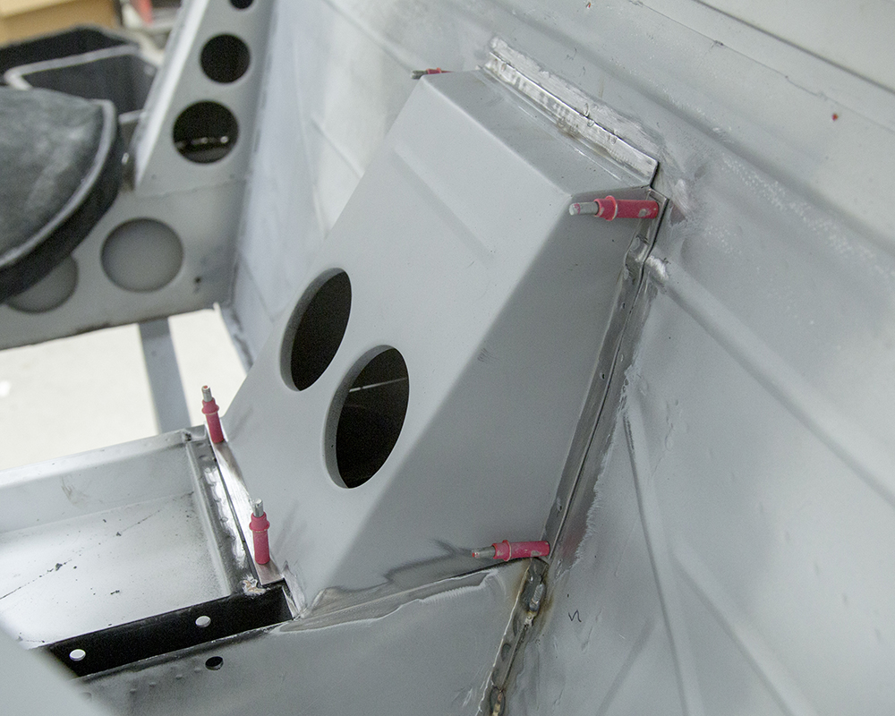
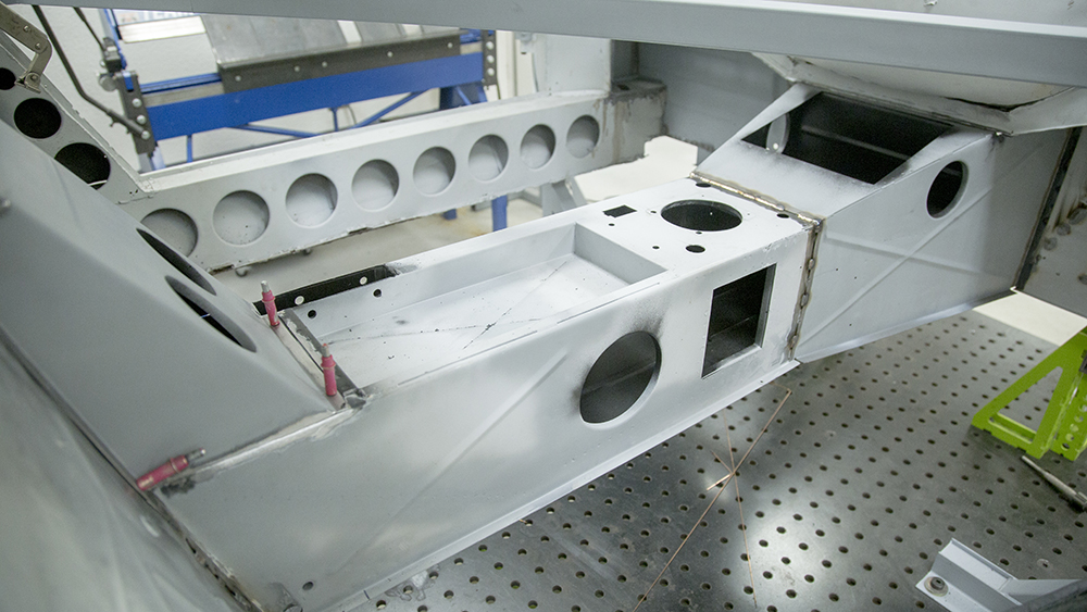
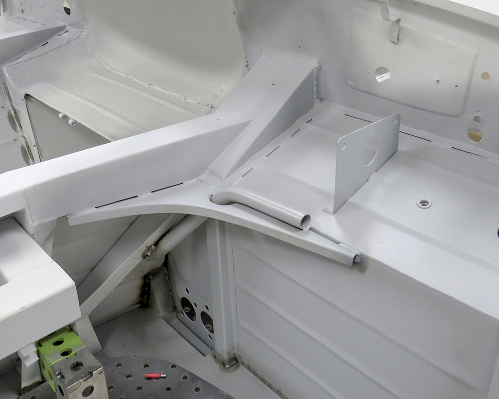
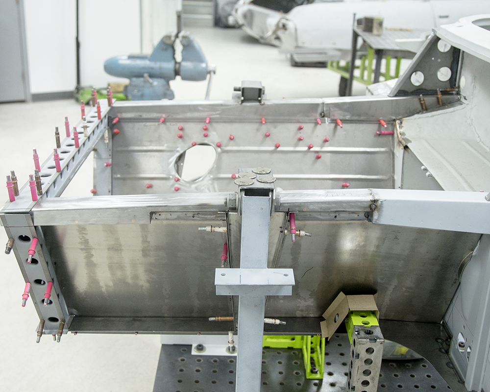
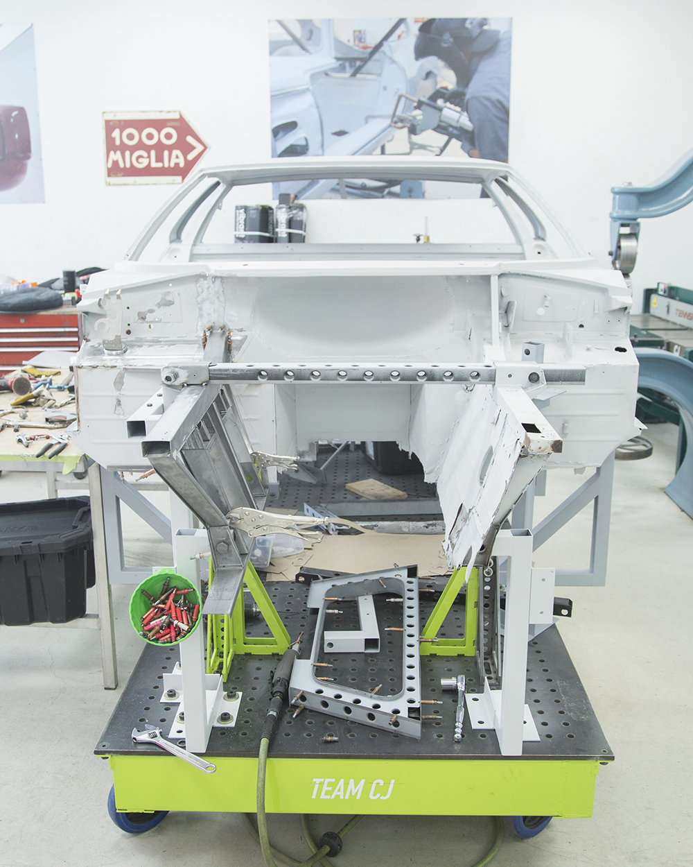
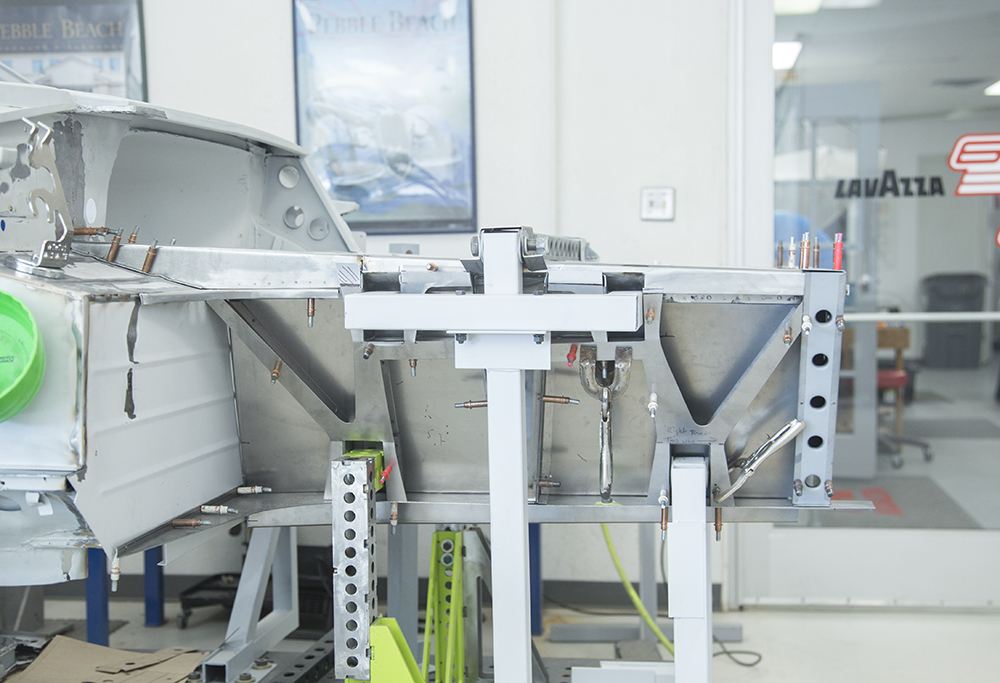
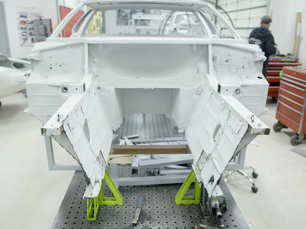
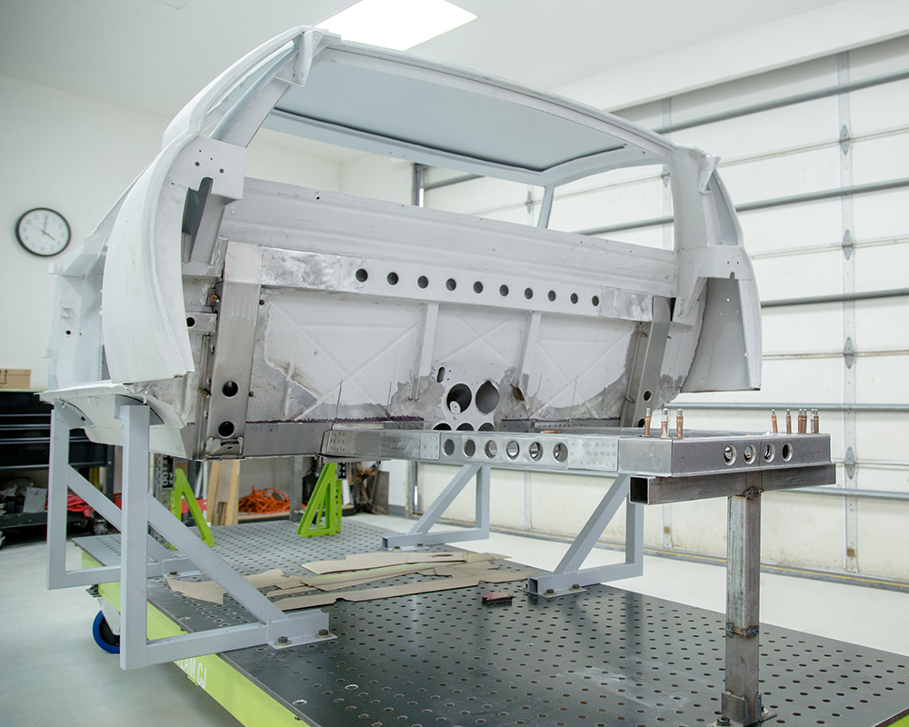
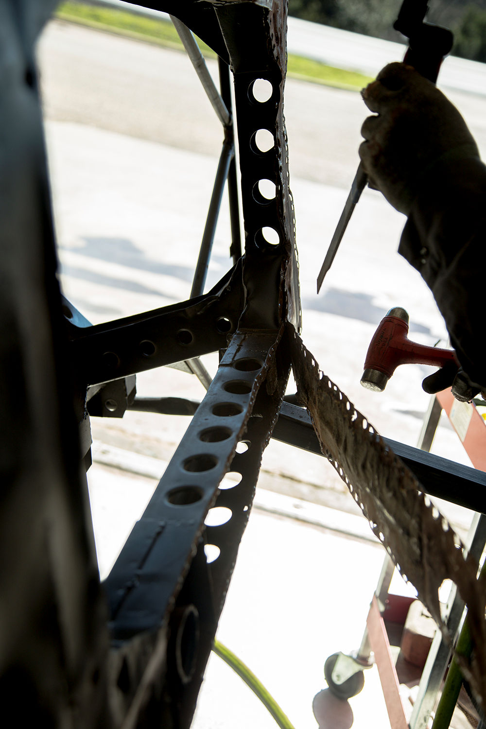
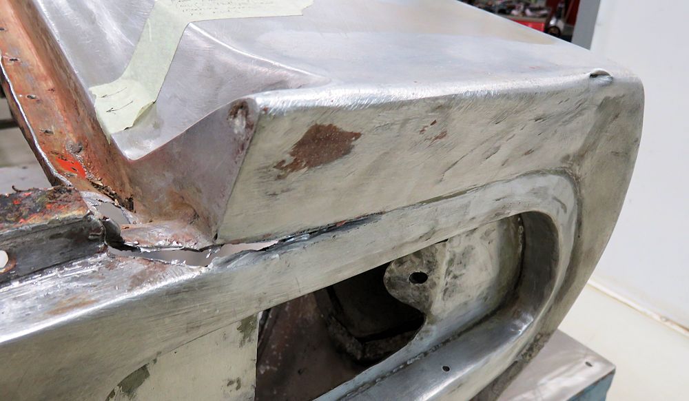
Repairing and reconstructing the
front of the car.
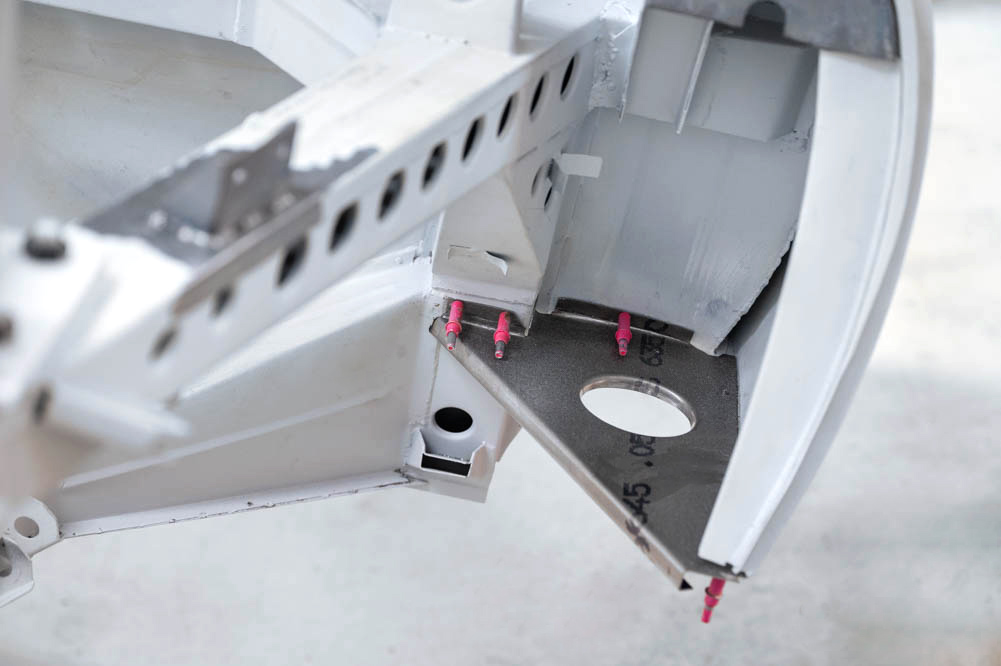
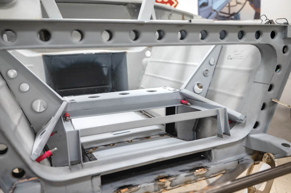
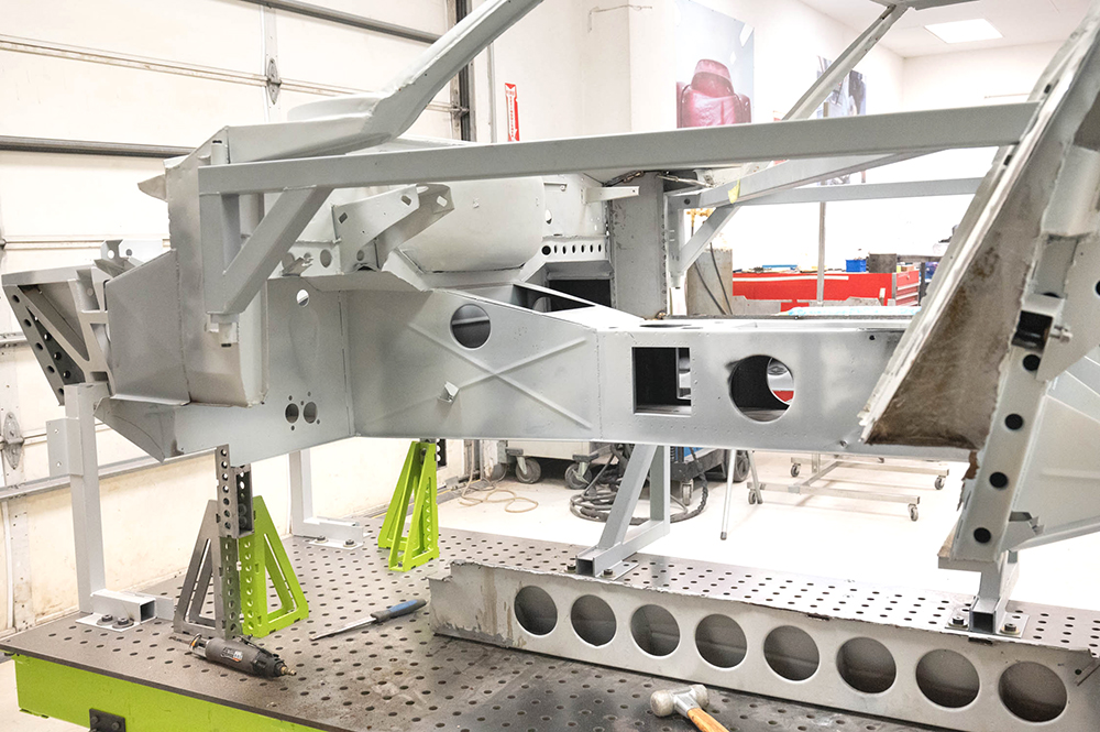
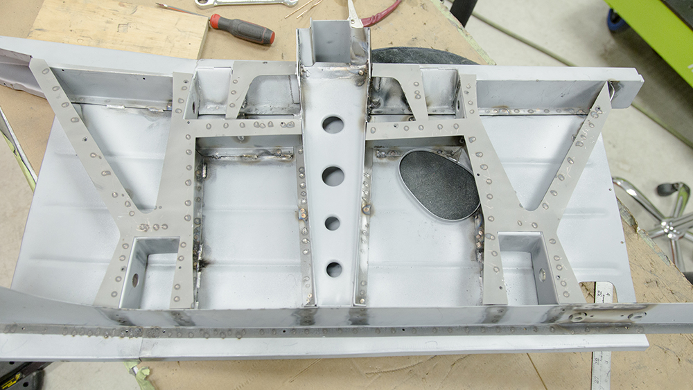
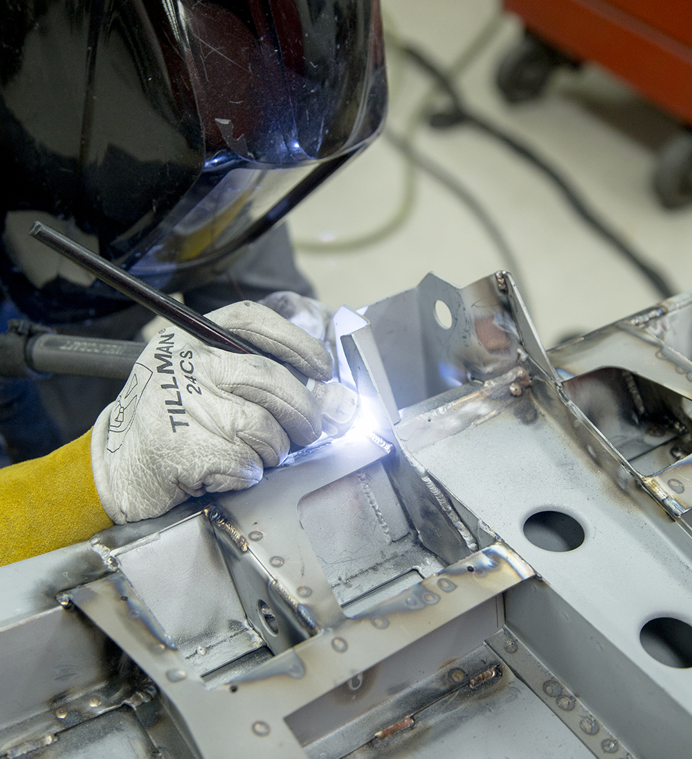
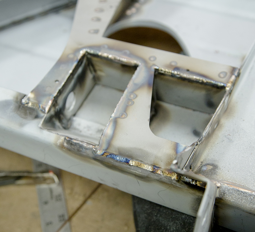
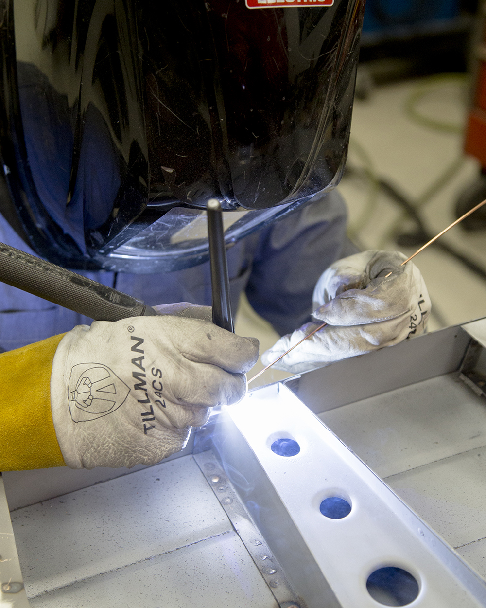
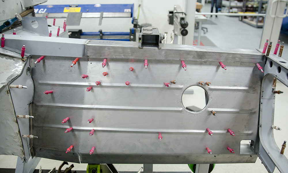
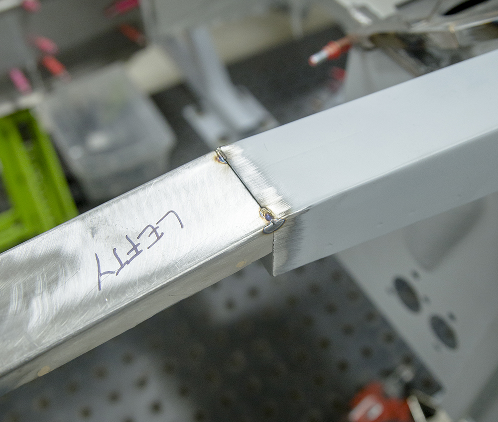
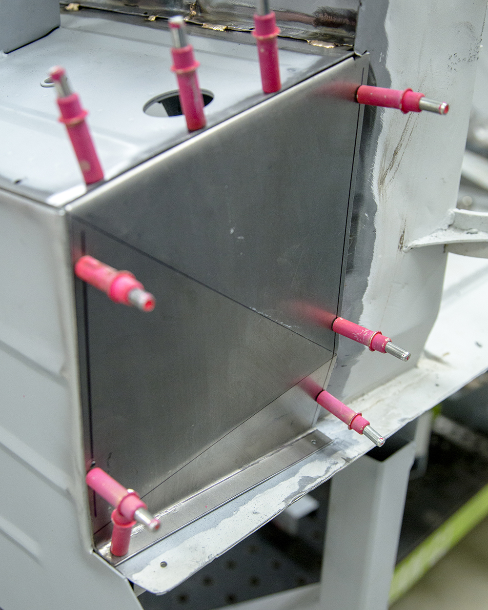
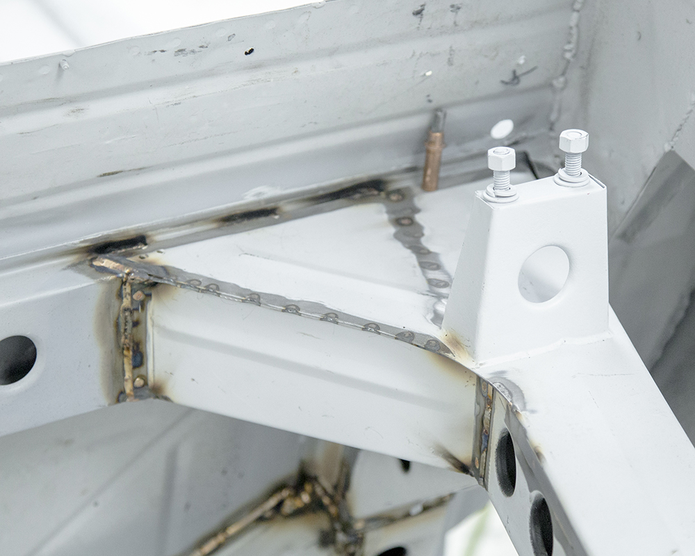
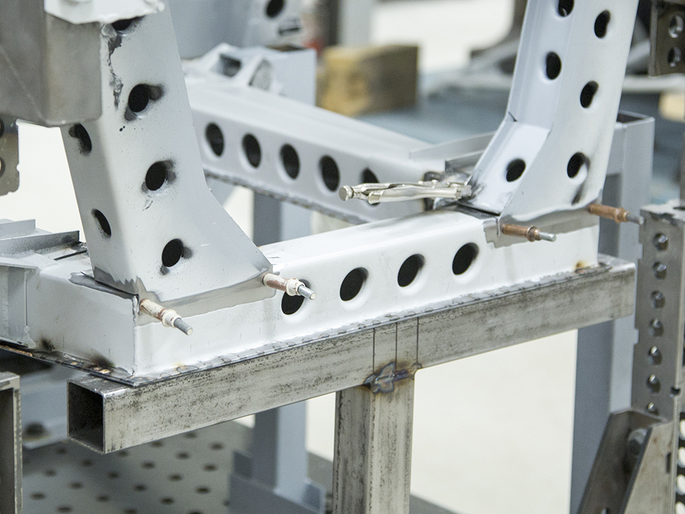
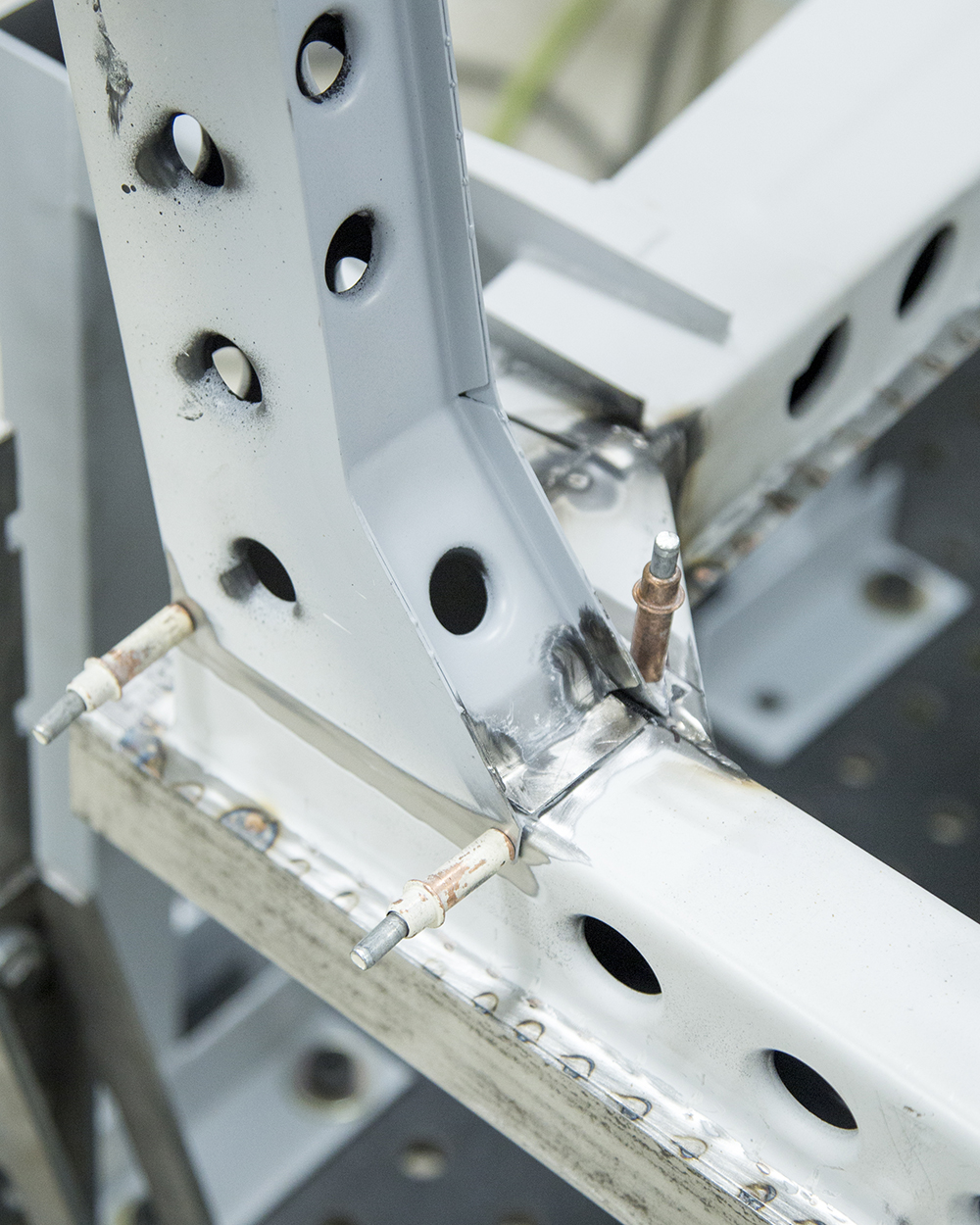
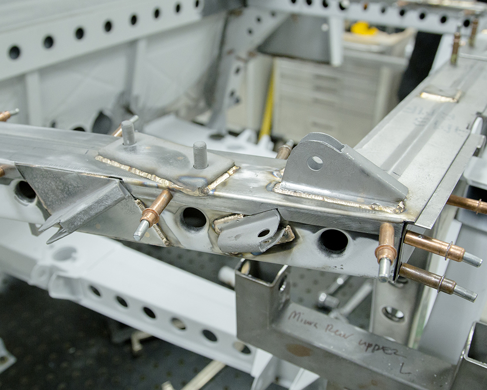
Update report - February
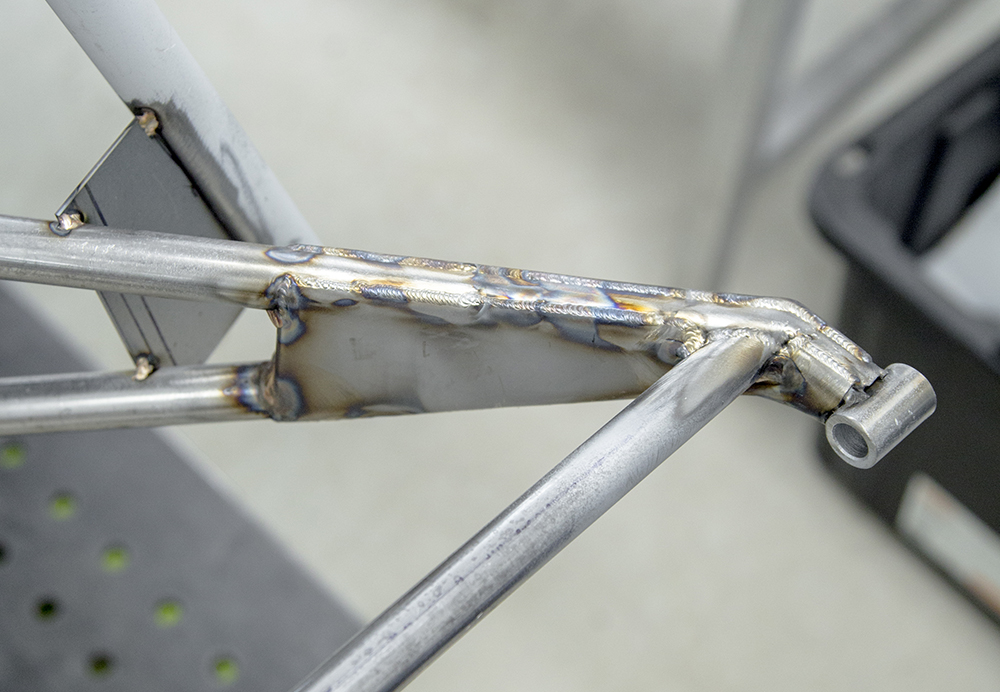
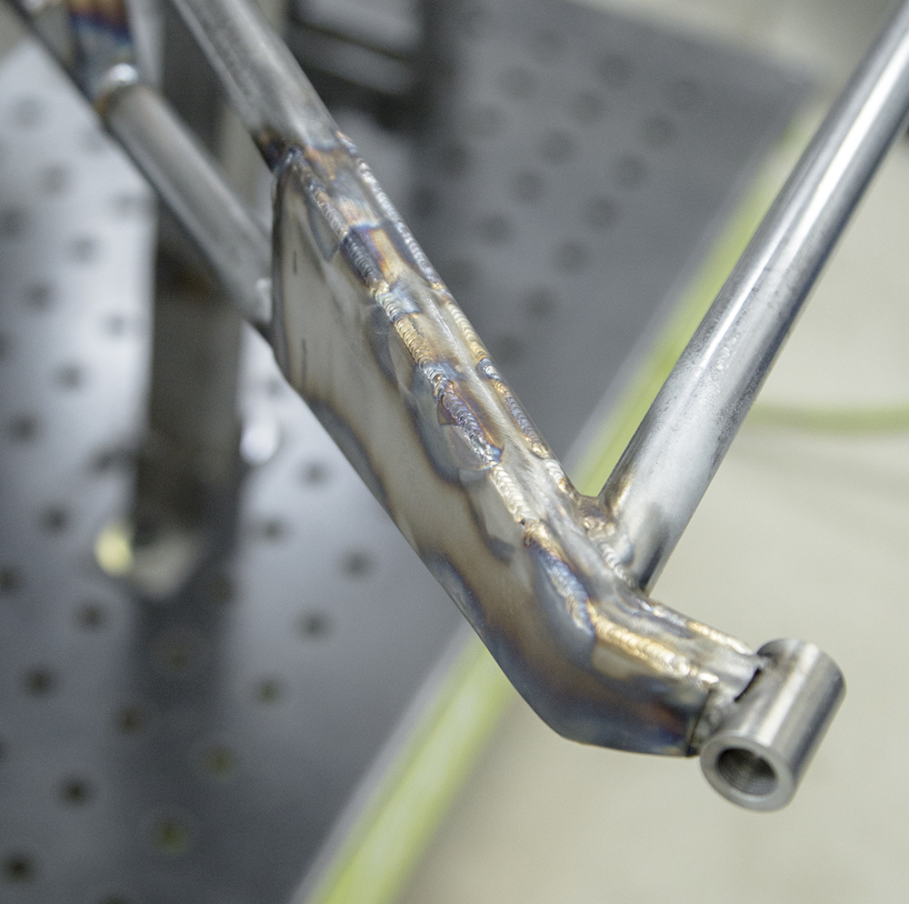
4, 2021
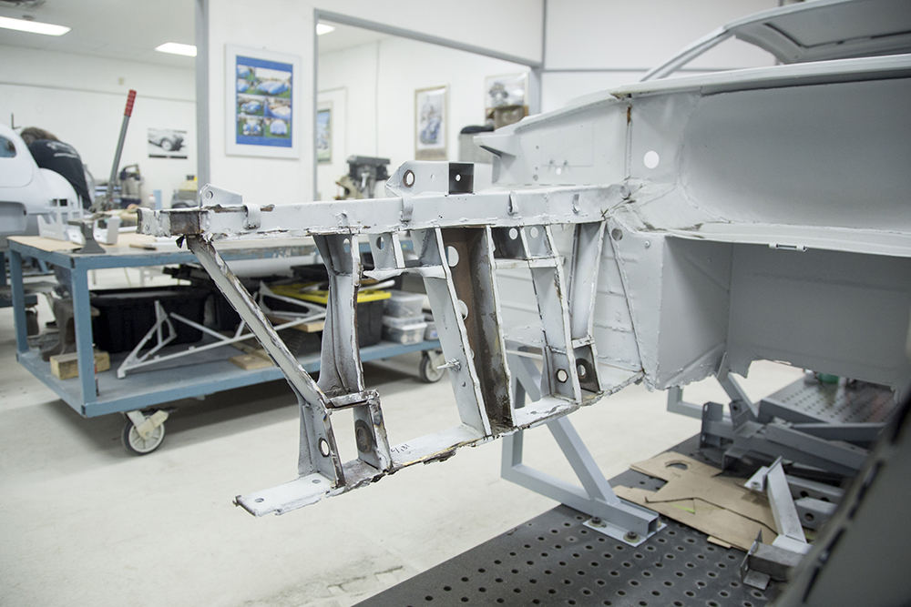
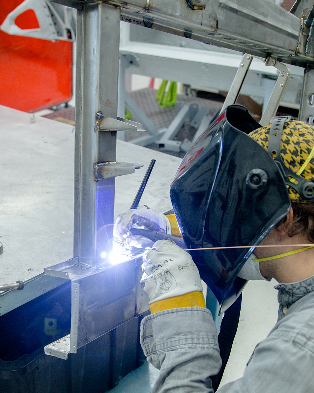
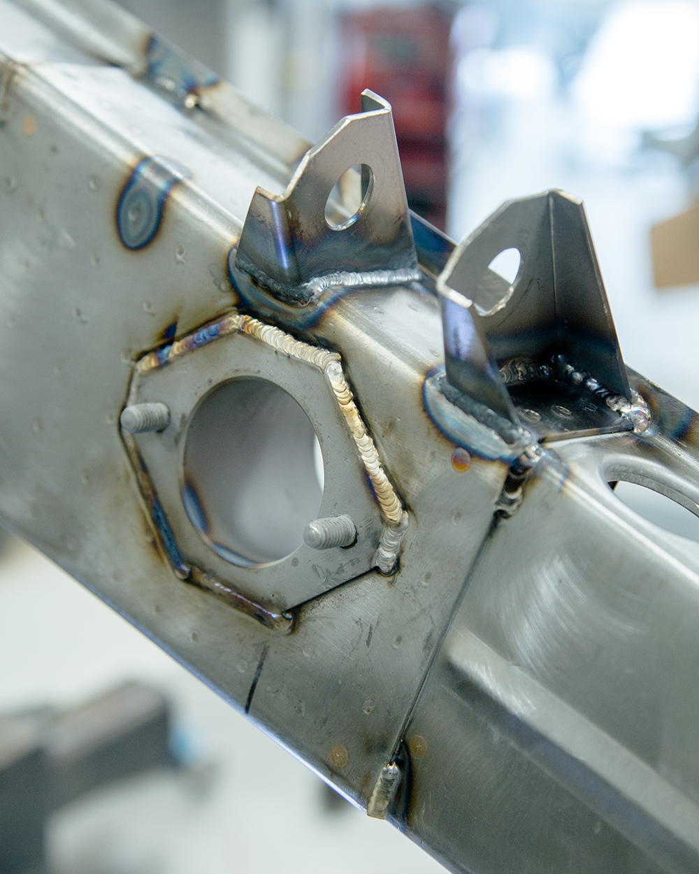
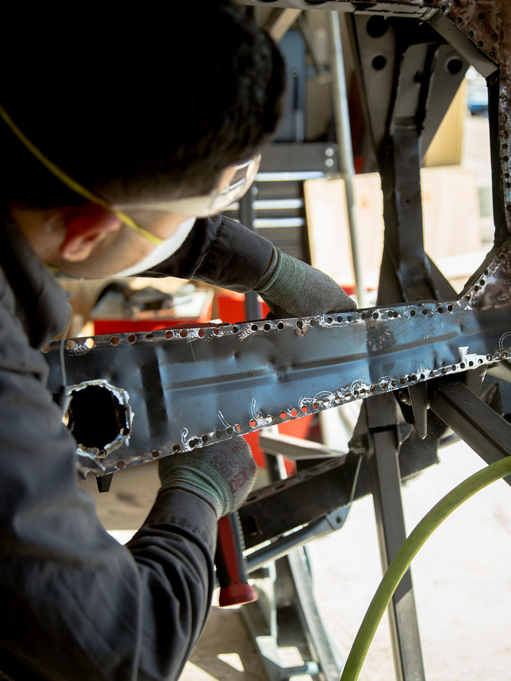
Andy has now
completed the fabrication and installation of the rear
chassis frame rails and has turned his expert attention to
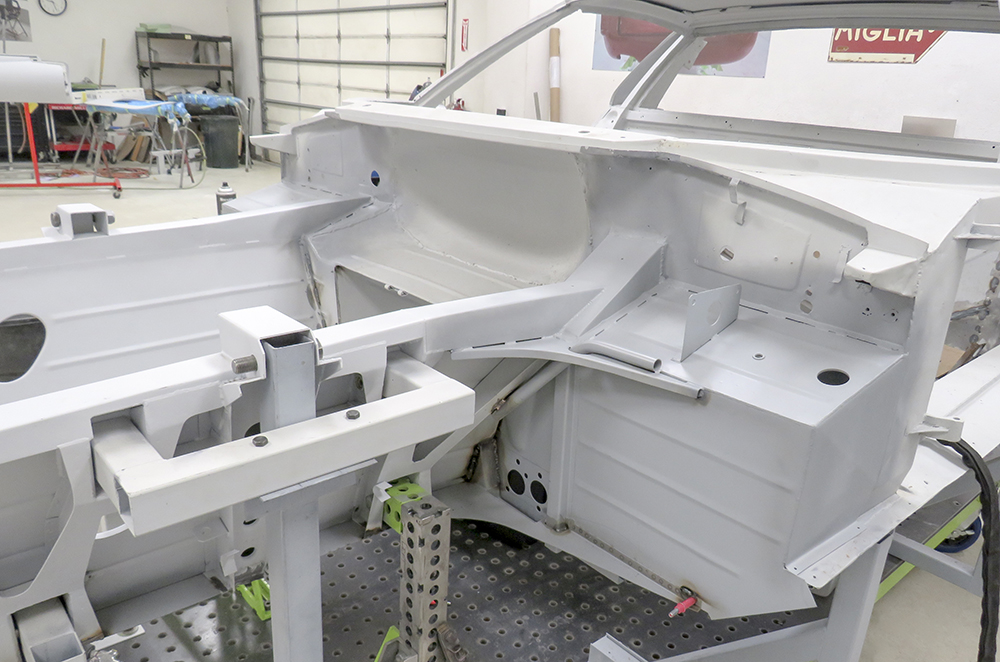
the front frame sections.
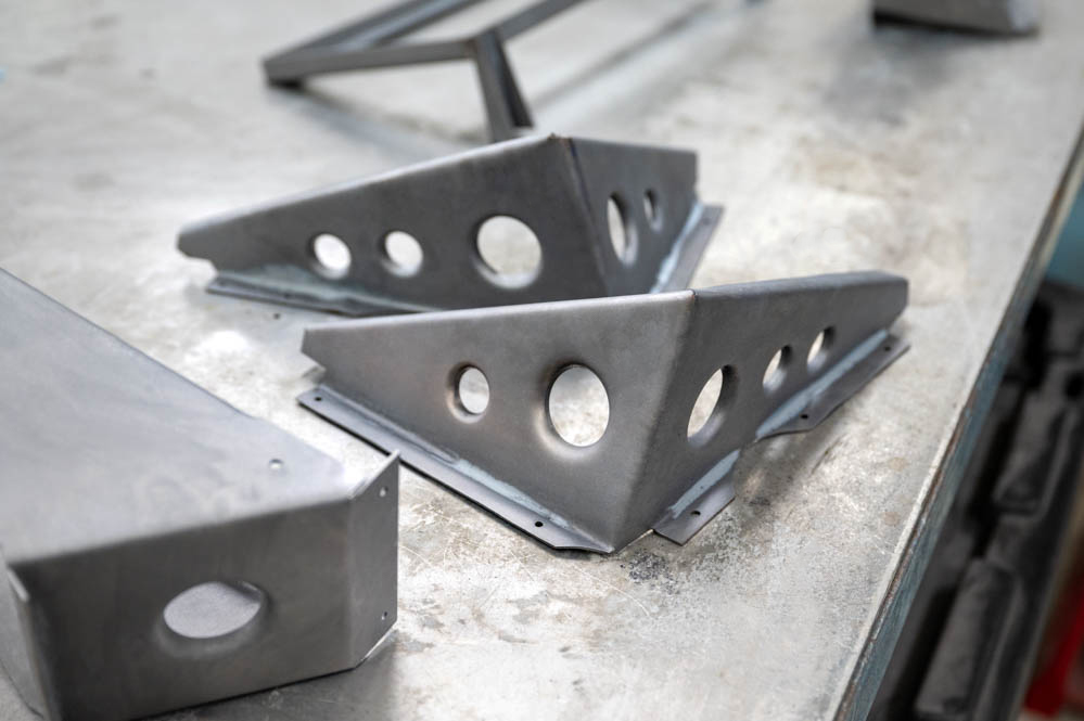
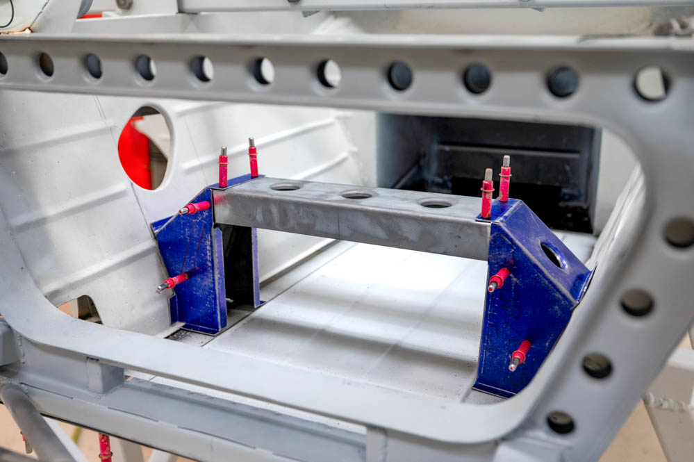
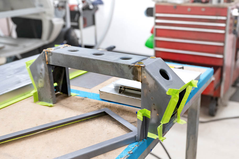
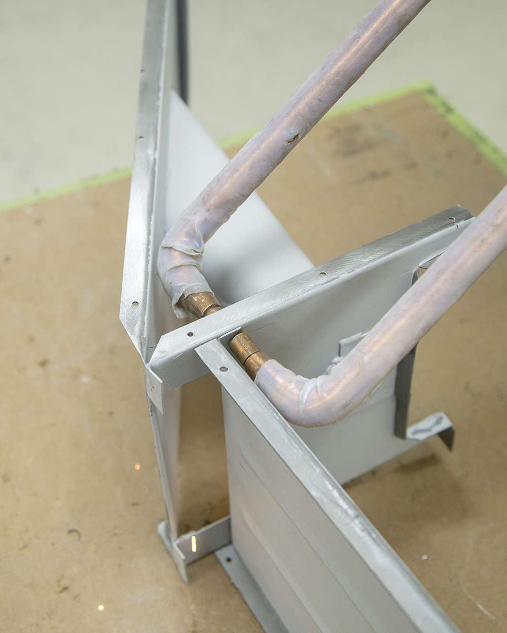
Starting to fabricate the new rear bonnet
hinge frame
Trial fitting the rear bonnet inner frame
to the
new bonnet hinge frame
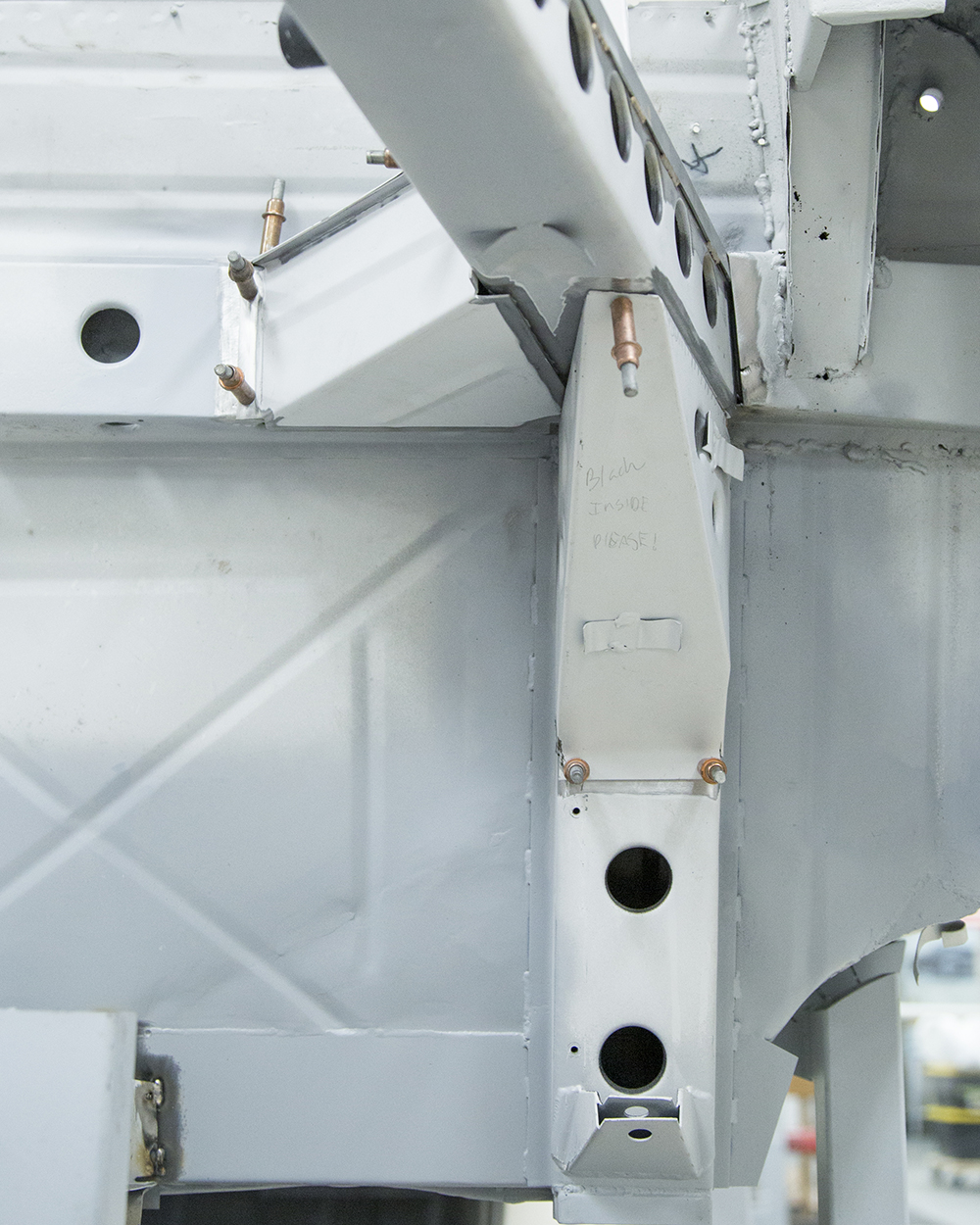
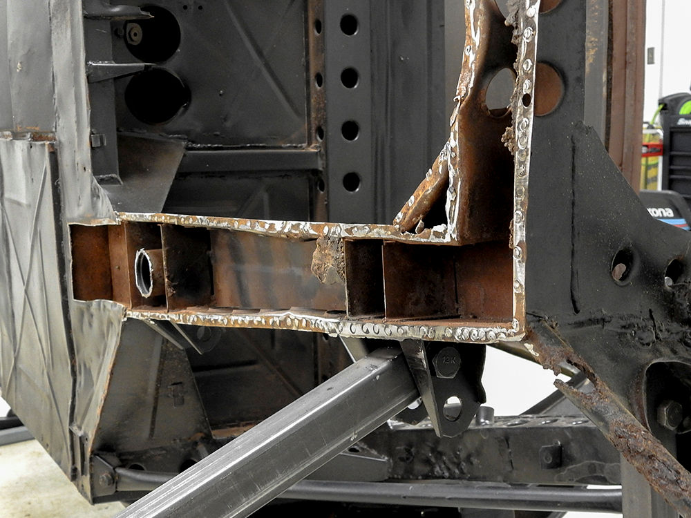
Time to move to the front frame repairs!
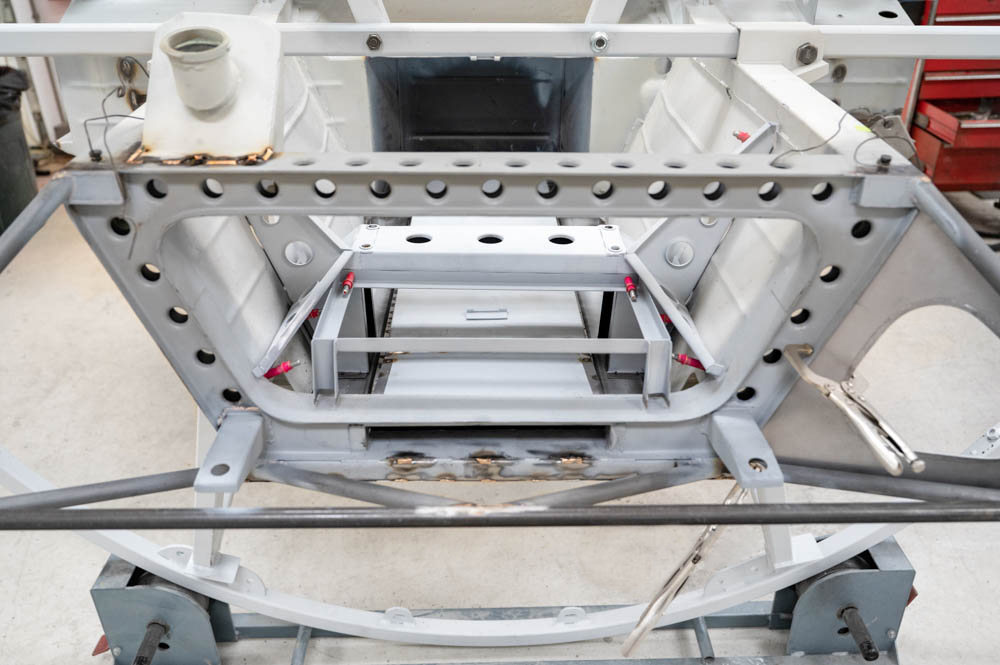
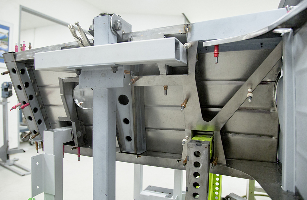
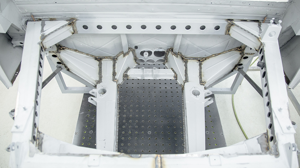
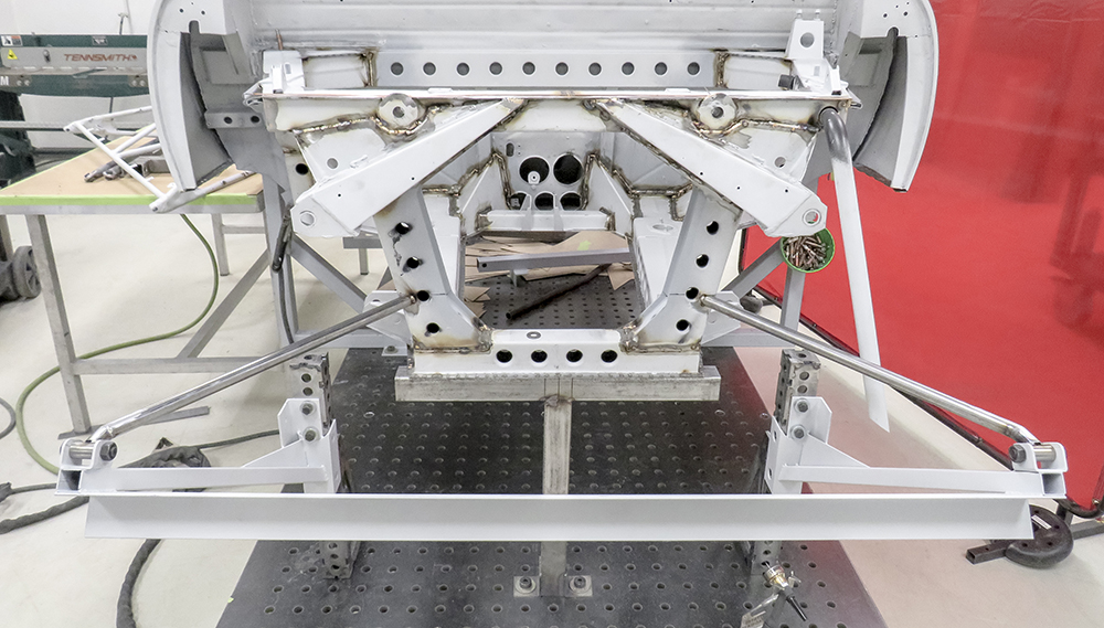
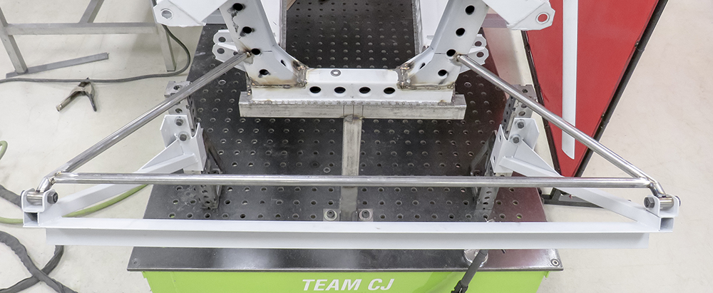
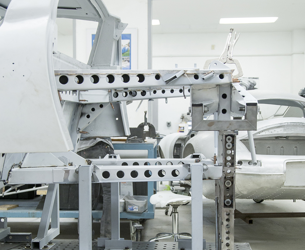
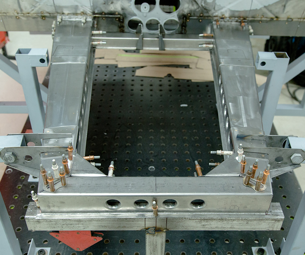
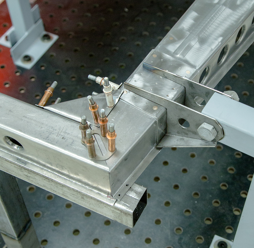
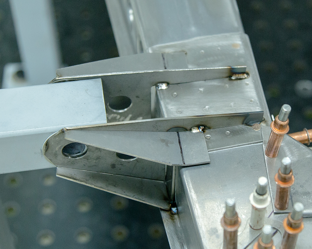
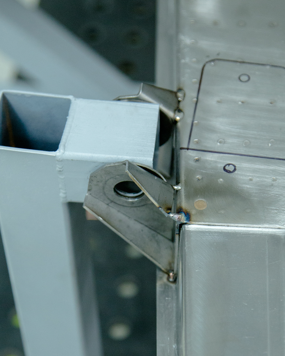
Update report - January 27, 2021
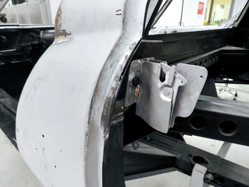
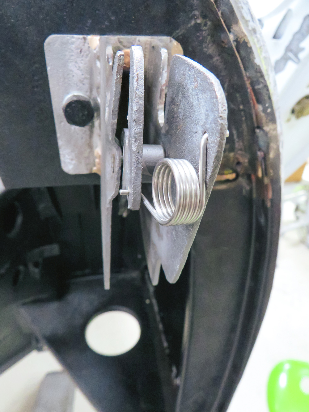
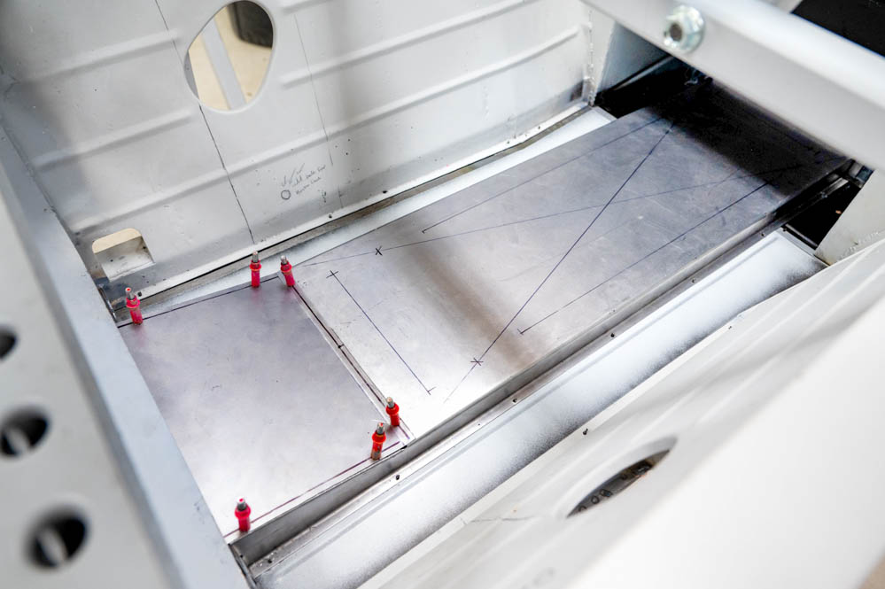
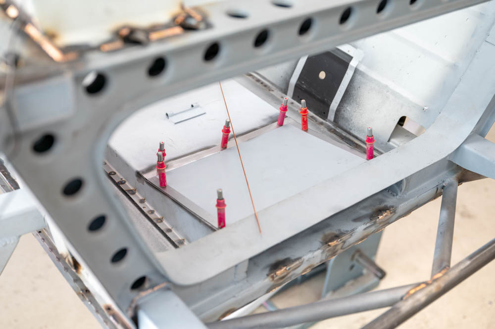
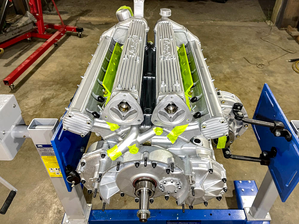
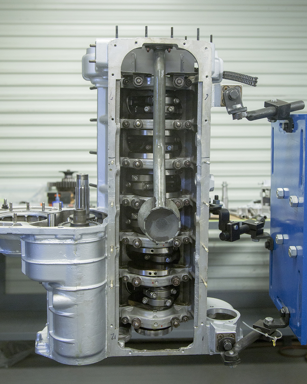
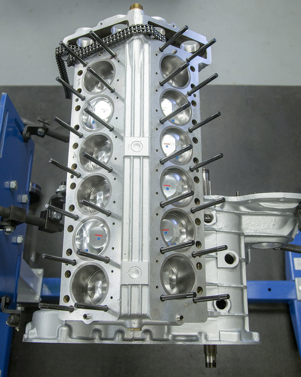
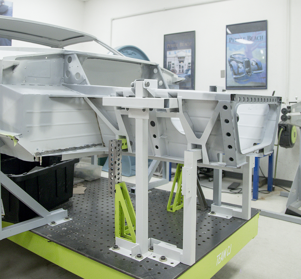
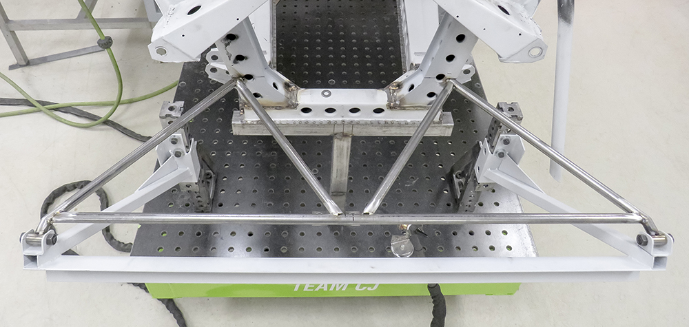
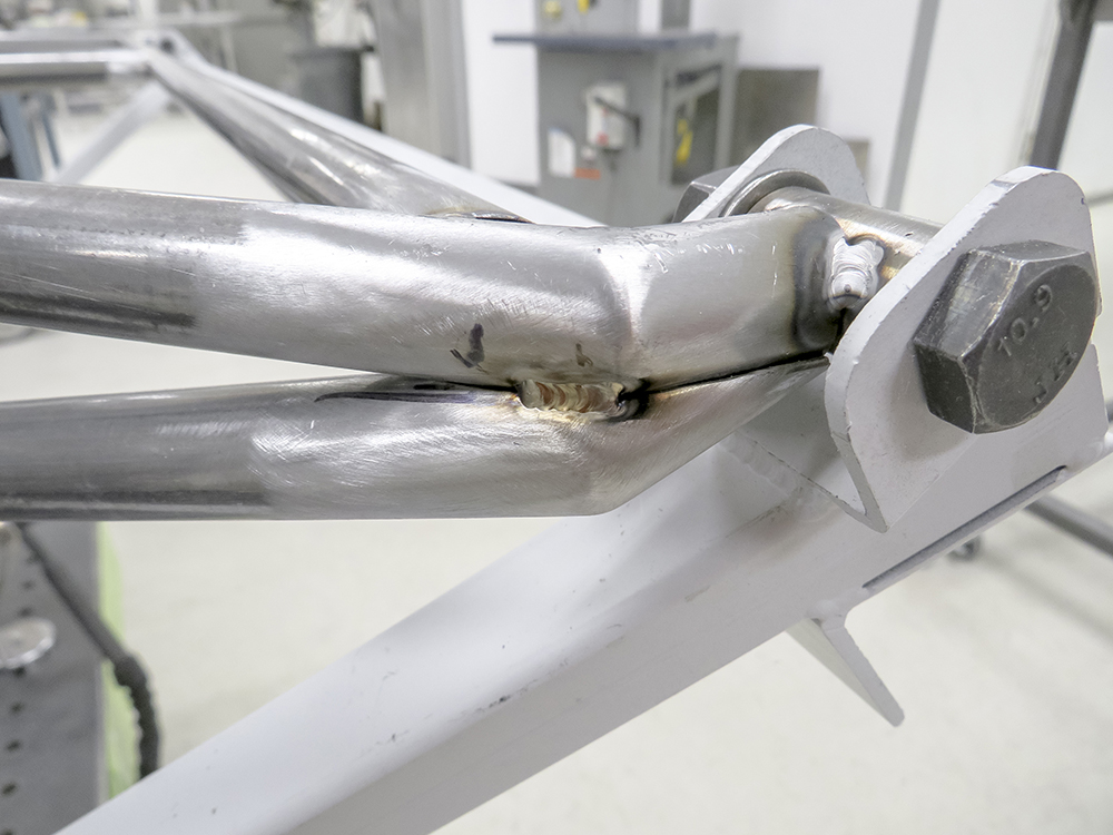
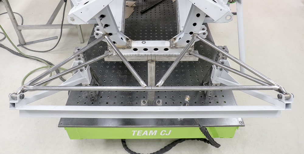
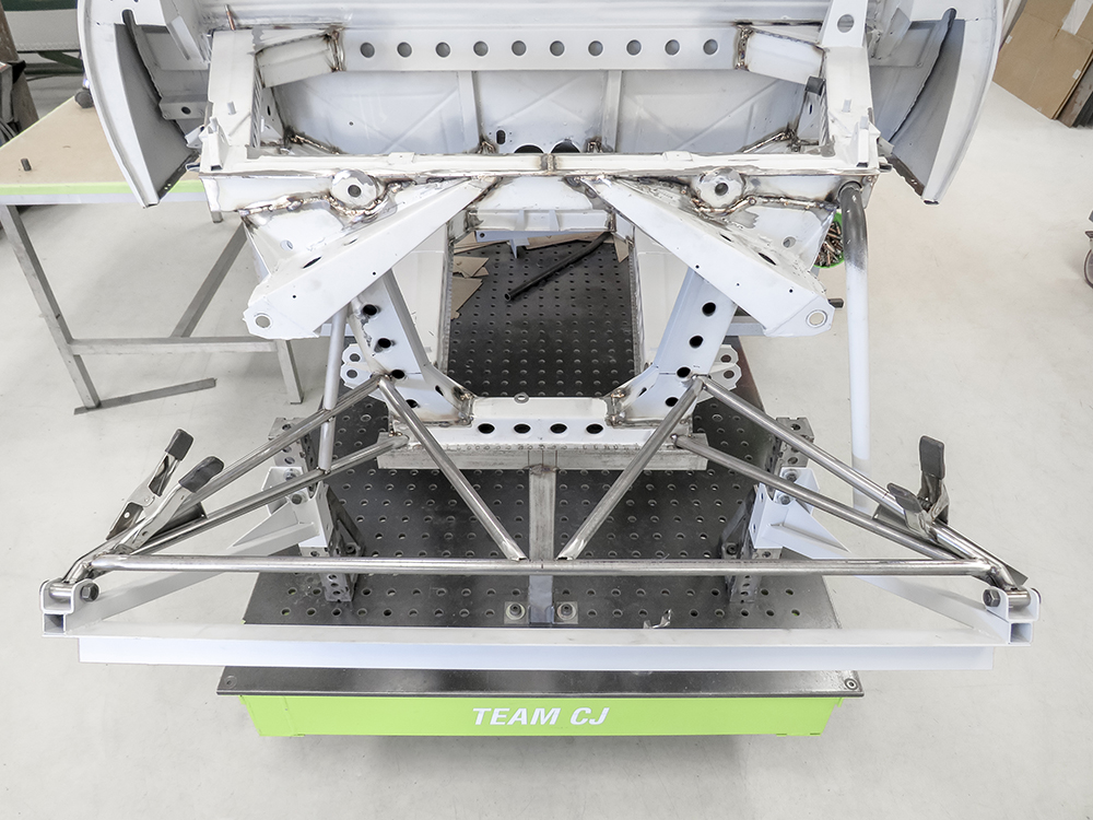
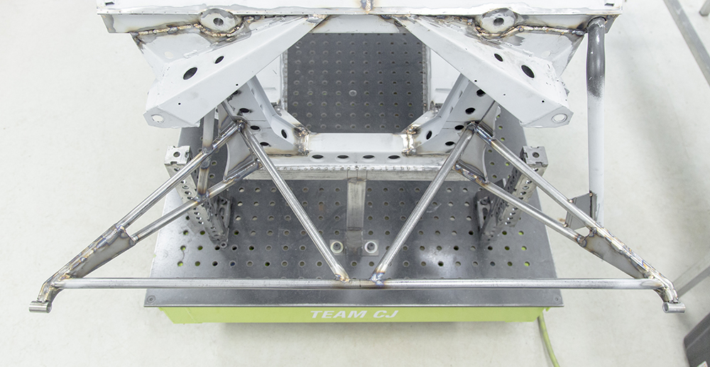
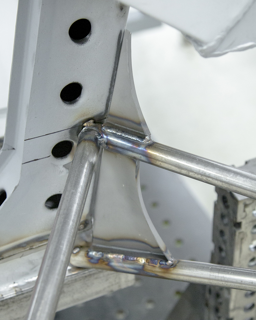
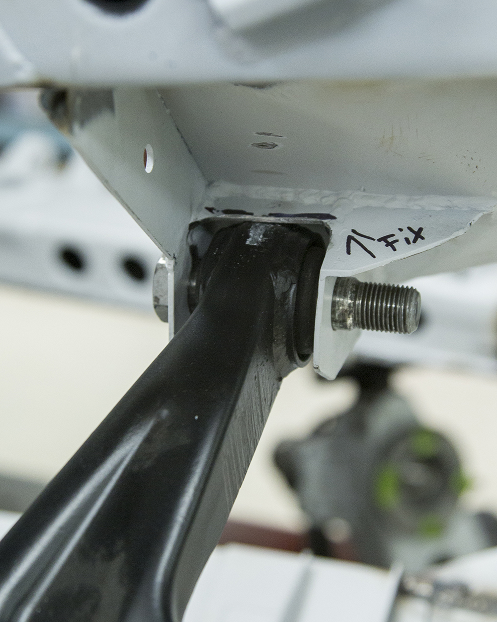
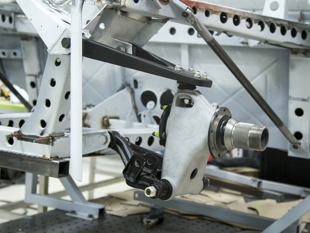
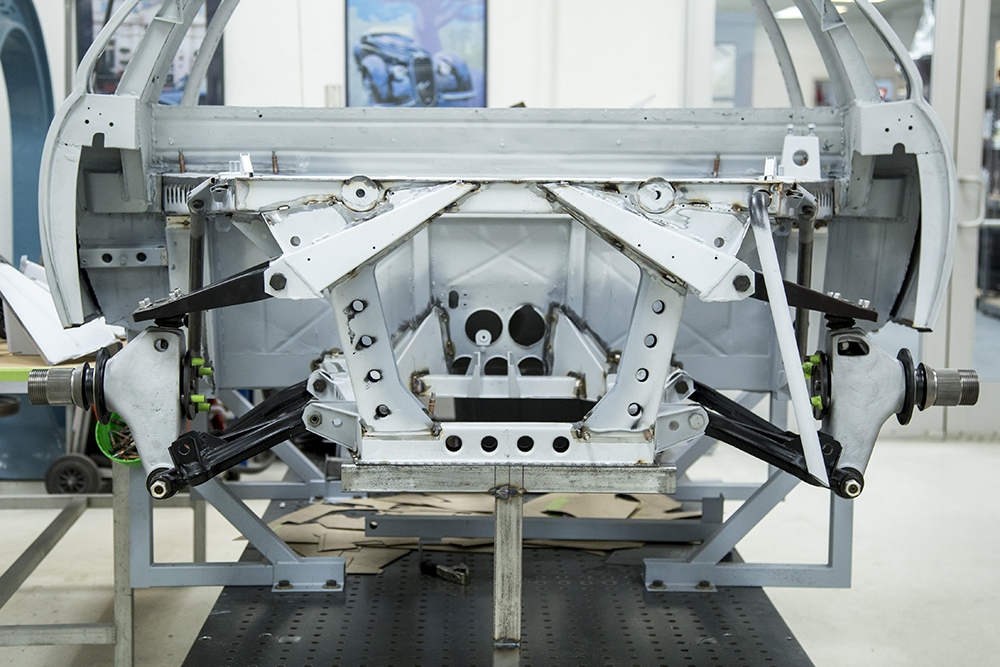
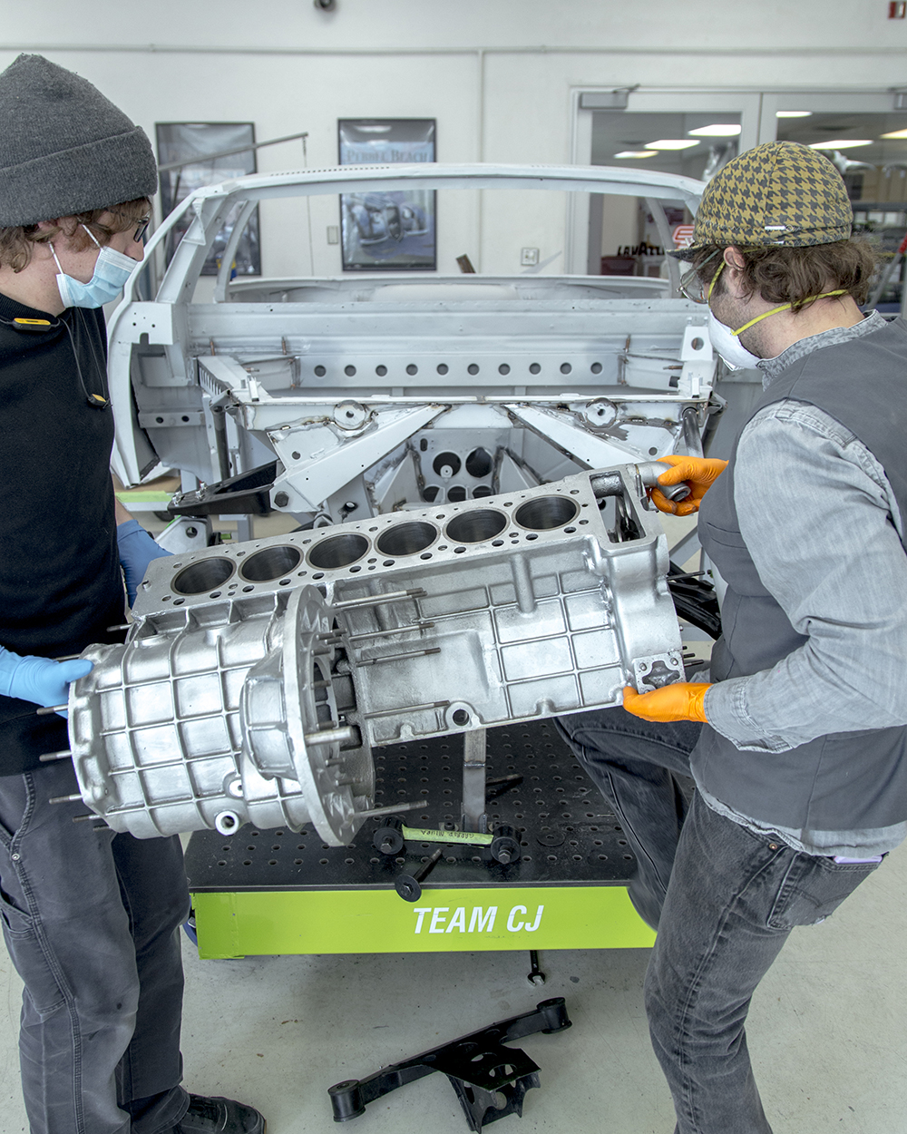
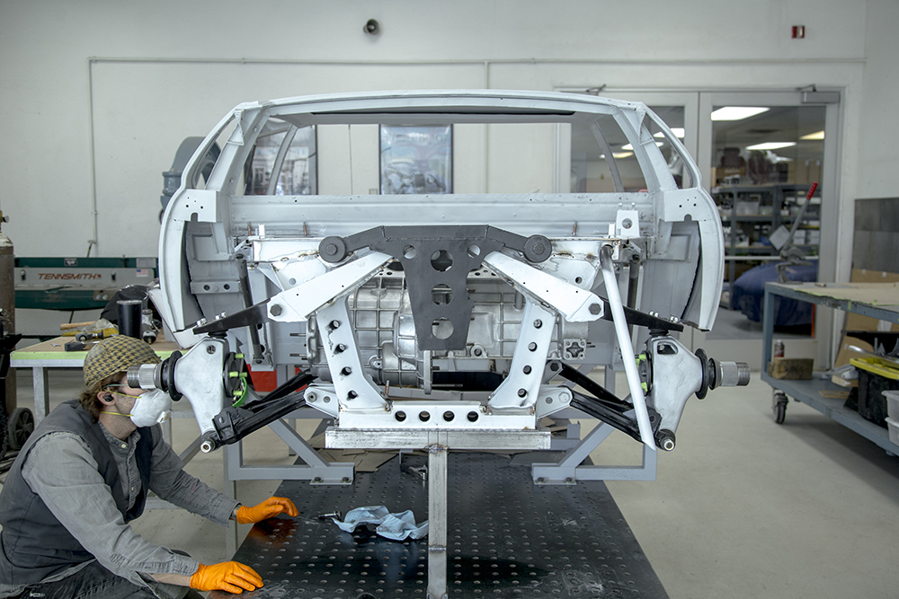
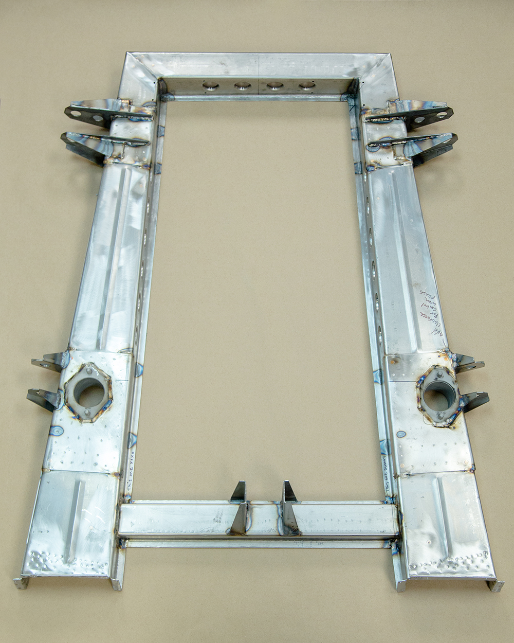
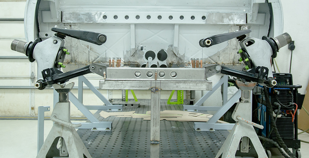
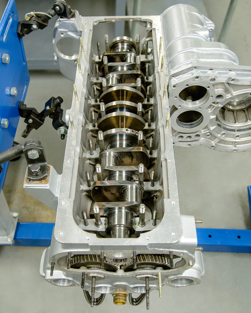
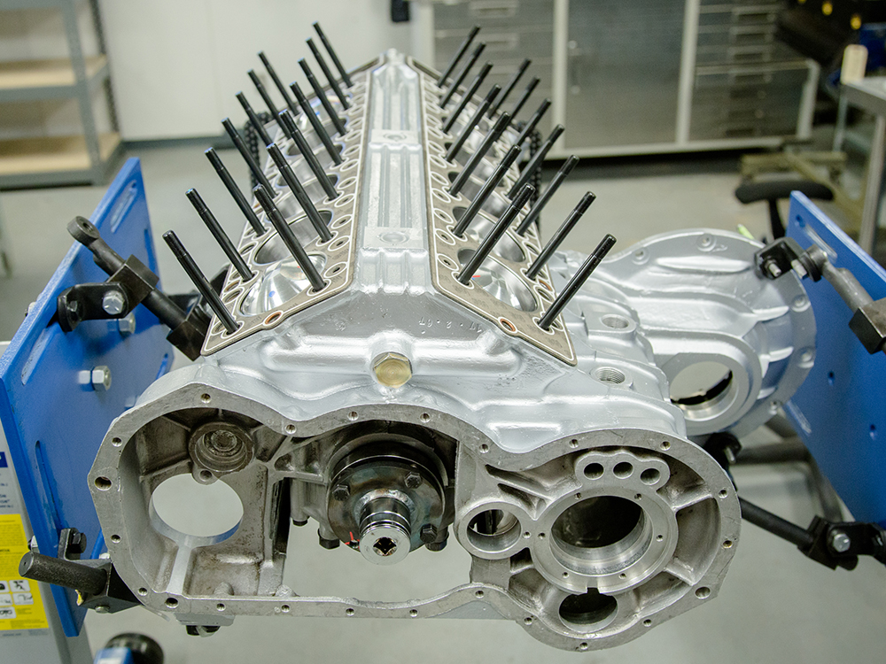
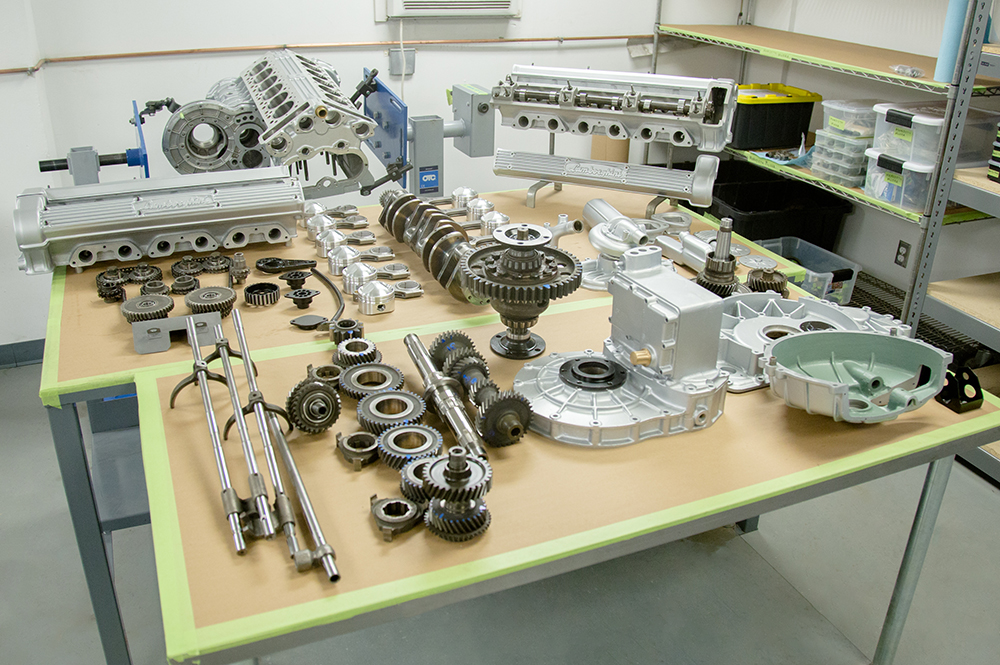
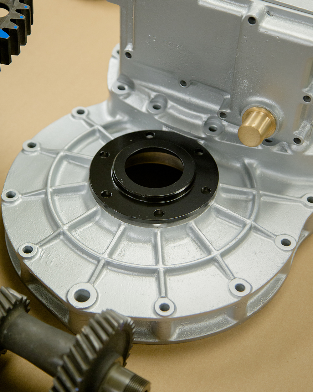
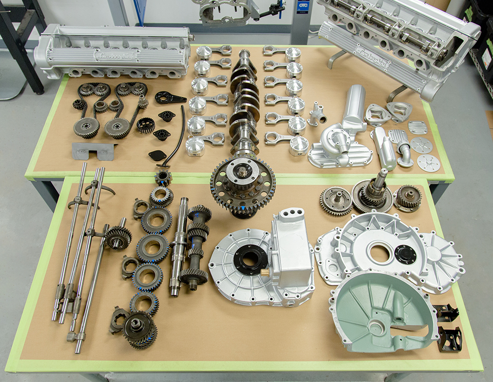
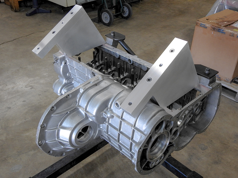
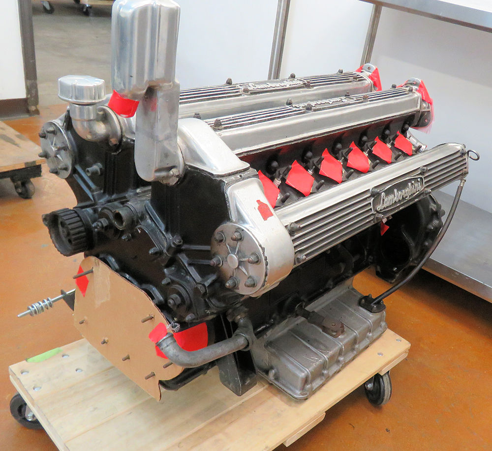
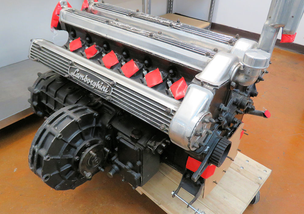
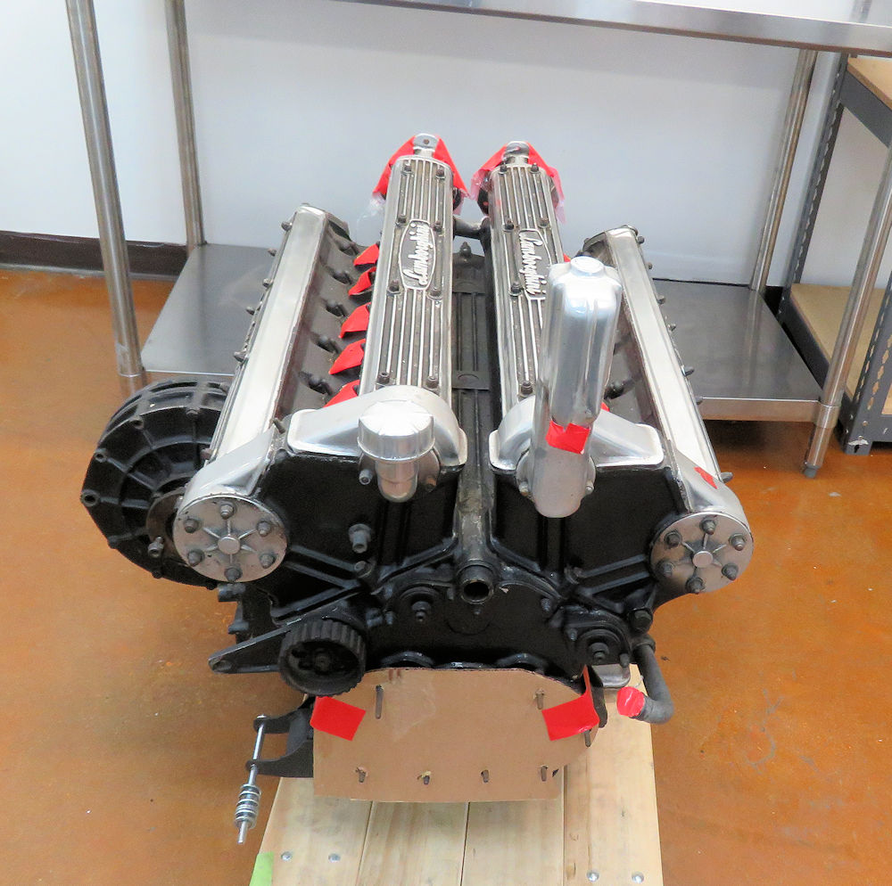
Trial fitting an engine block and rear
suspension after reconstructing the rear frame rails and
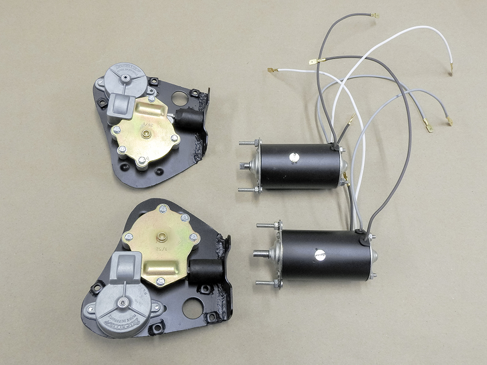
engine cradle.The last photos in the sequence show some of the
components and motors that have been rebuilt/restored.
Trial fitting rear suspension
A perfect example of why we trial fit
items like this!
Everything is lining up perfectly
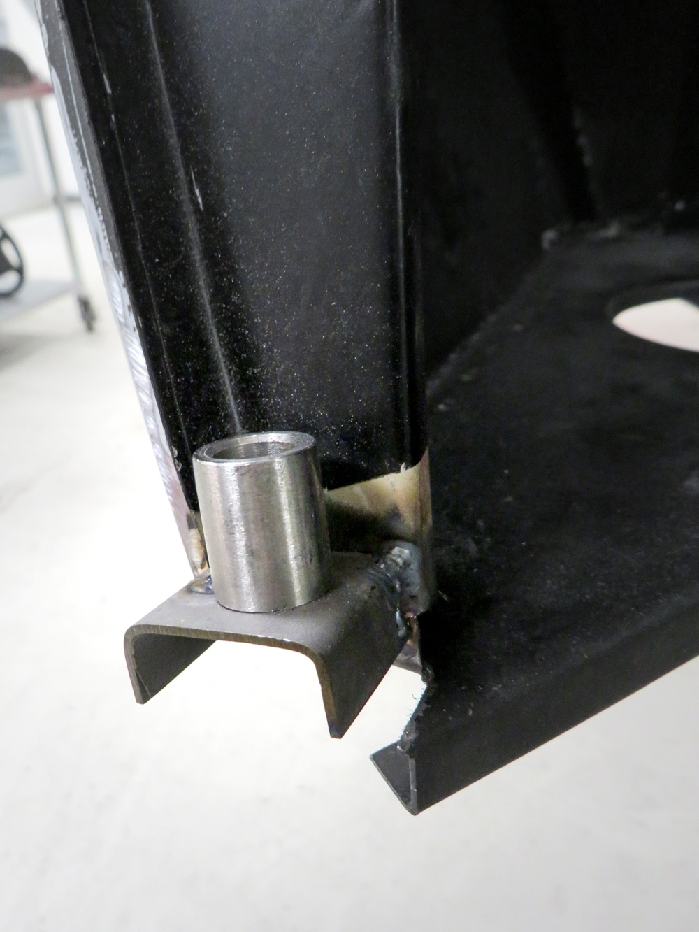
Trial fitting the block to make sure we
have the
engine mounts in the perfect location
Checking for desired clearance between
the block
and the lower frame rail
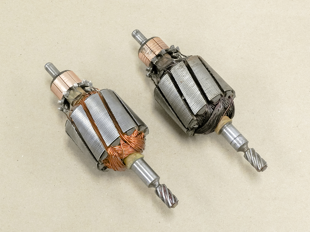
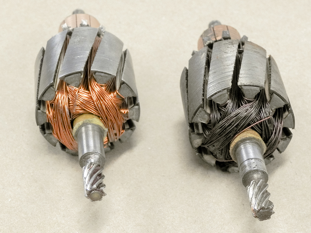
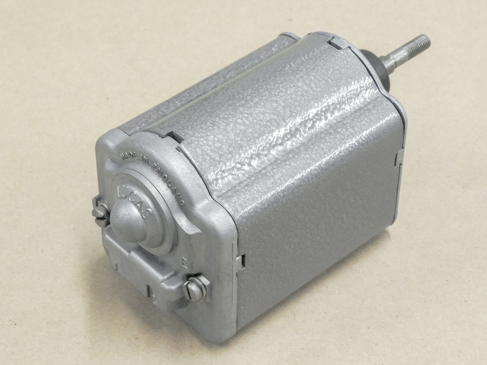
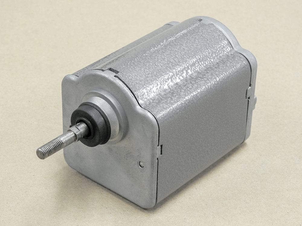
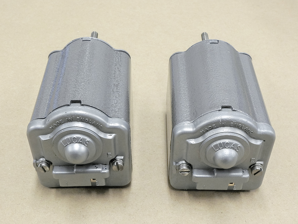
Headlamp motors rebuilt and restored
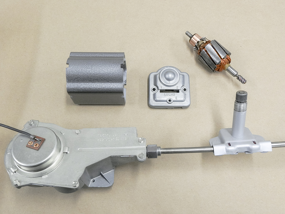
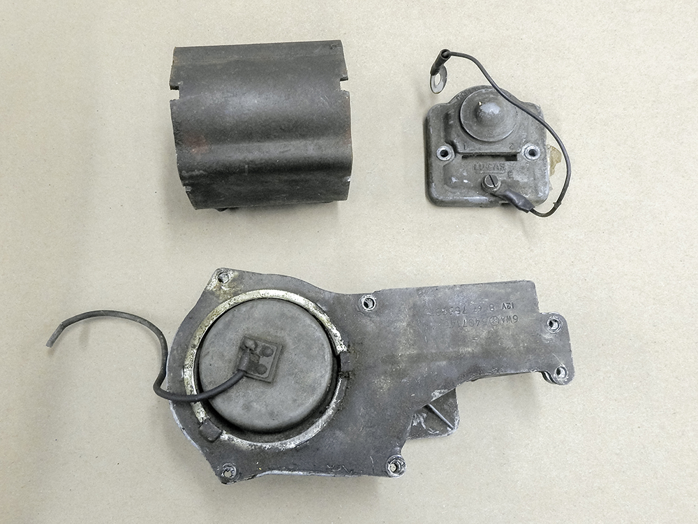
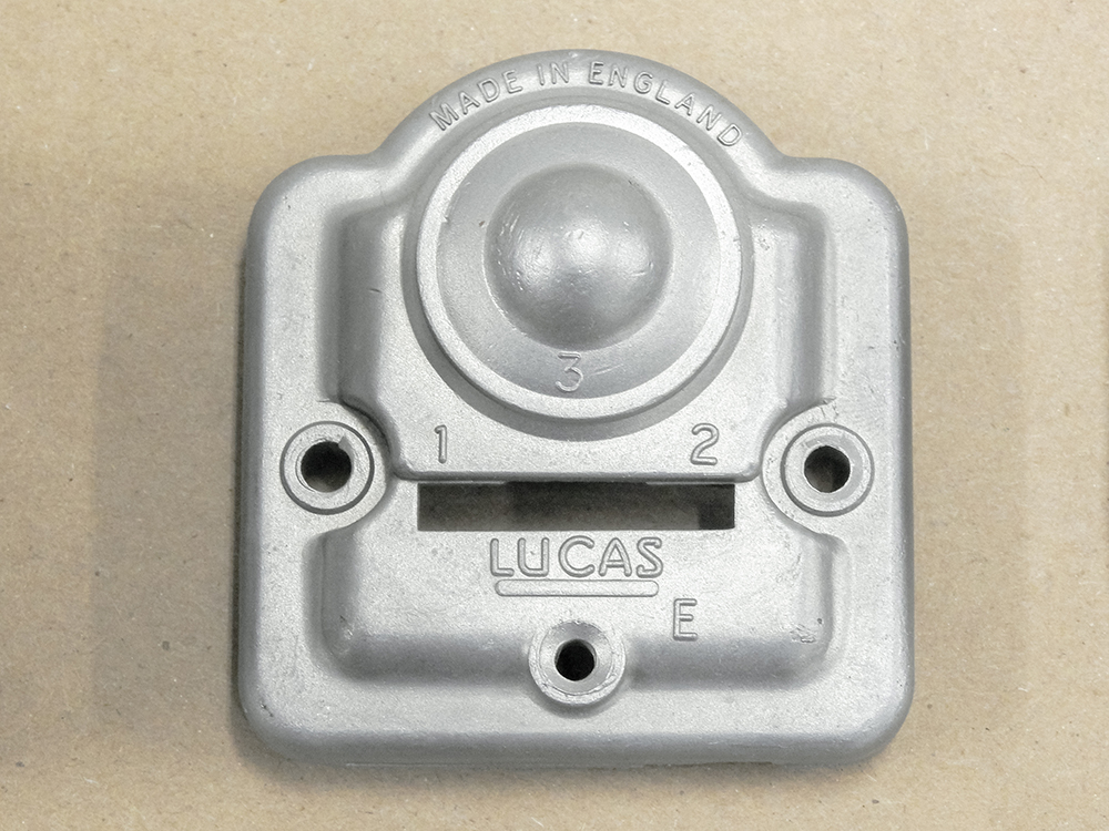
Wiper motor and rack have been rebuilt
and restored
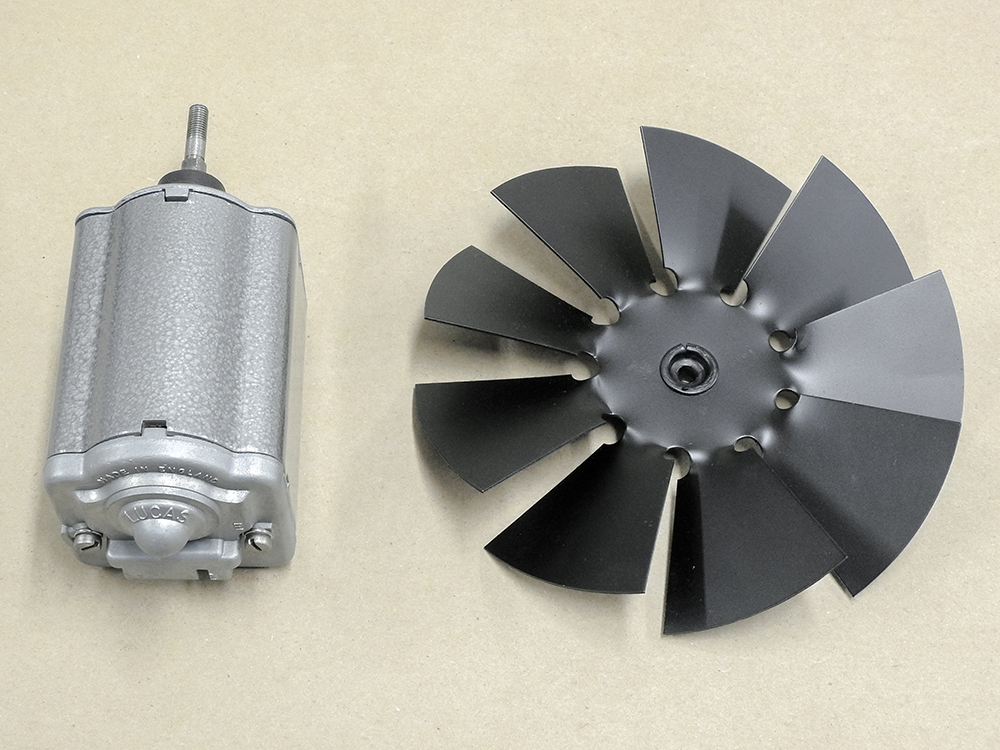
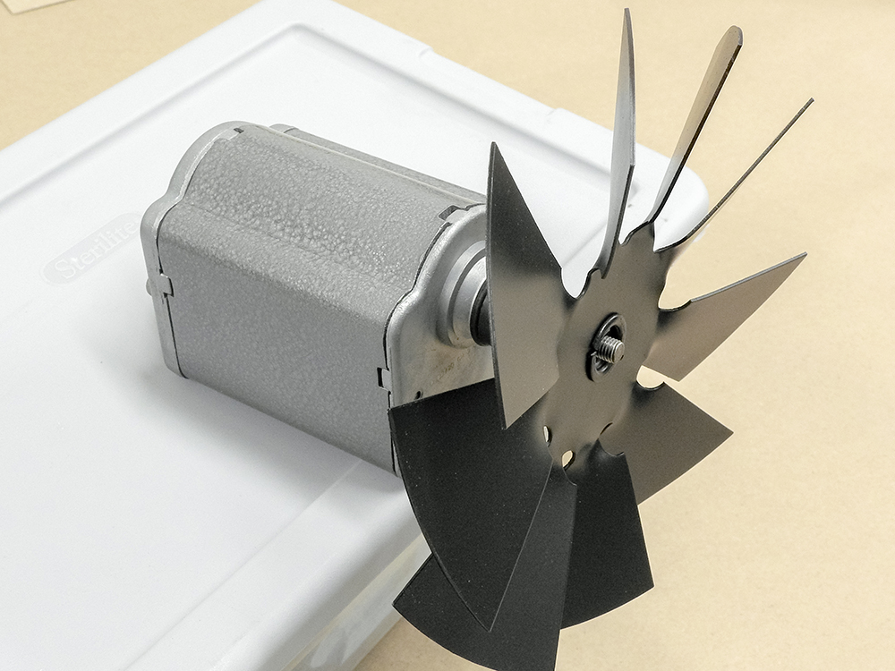
Rebuilding the cooling fan motors
Update report - January 26, 2021
Update report - January 21, 2021
More great
progress in the Coachworks.
Update report - January 8, 2021
Lots of progress
in the Coachworks this week!
Update report - January 5, 2021
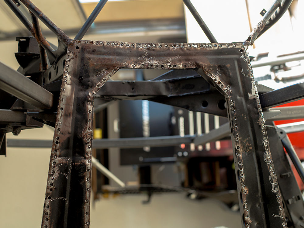
Andy continues to make great progress with the rear frame
rail fabrication.
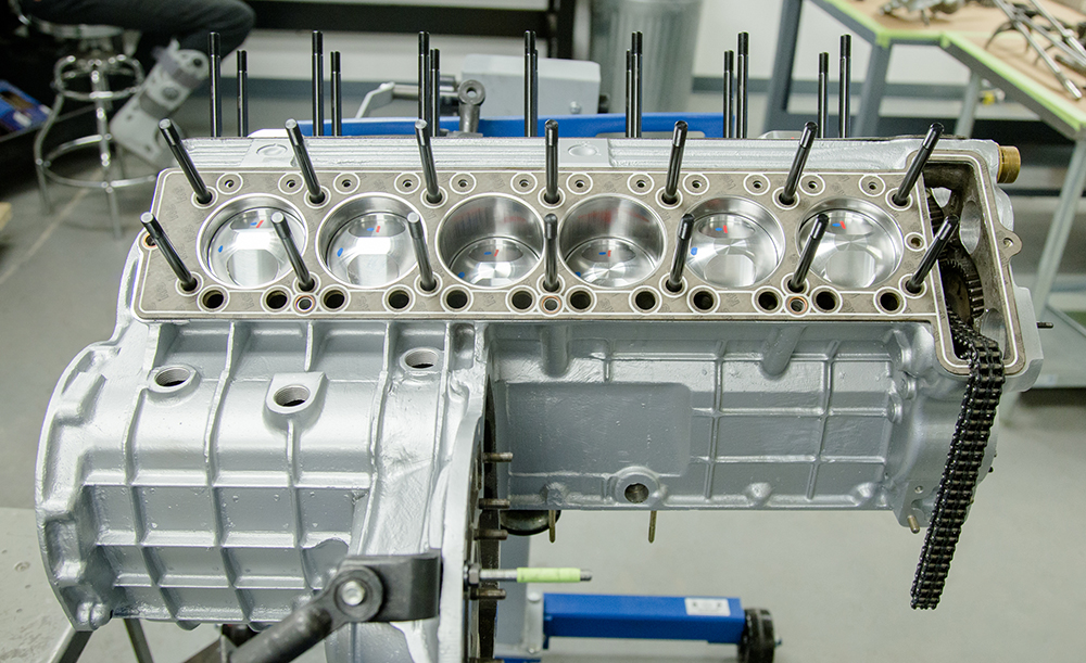
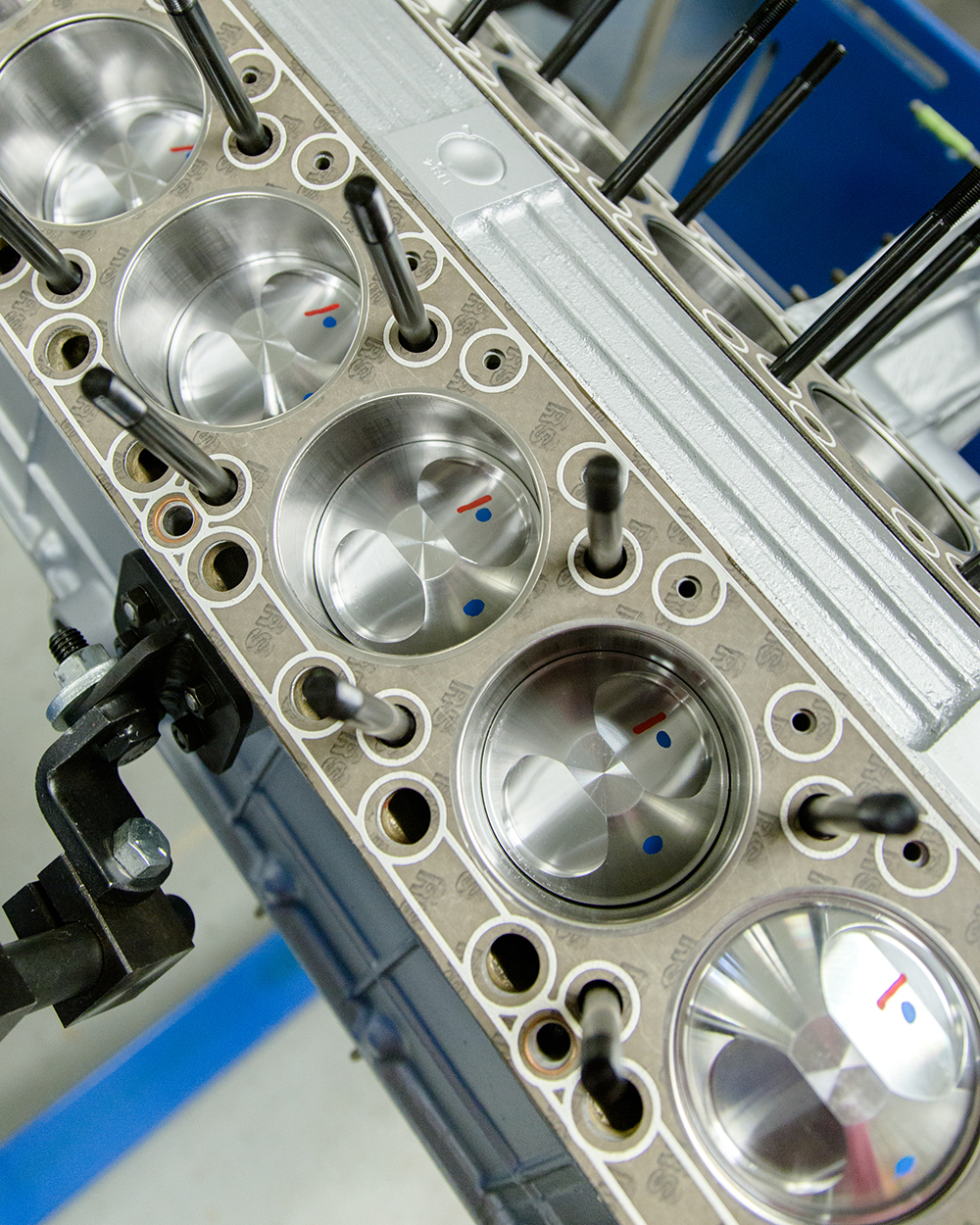
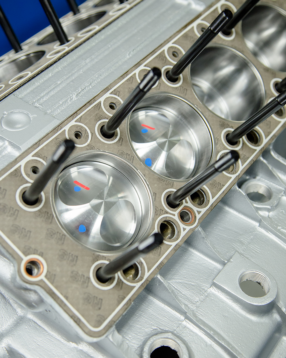
Update report - December 17, 2020
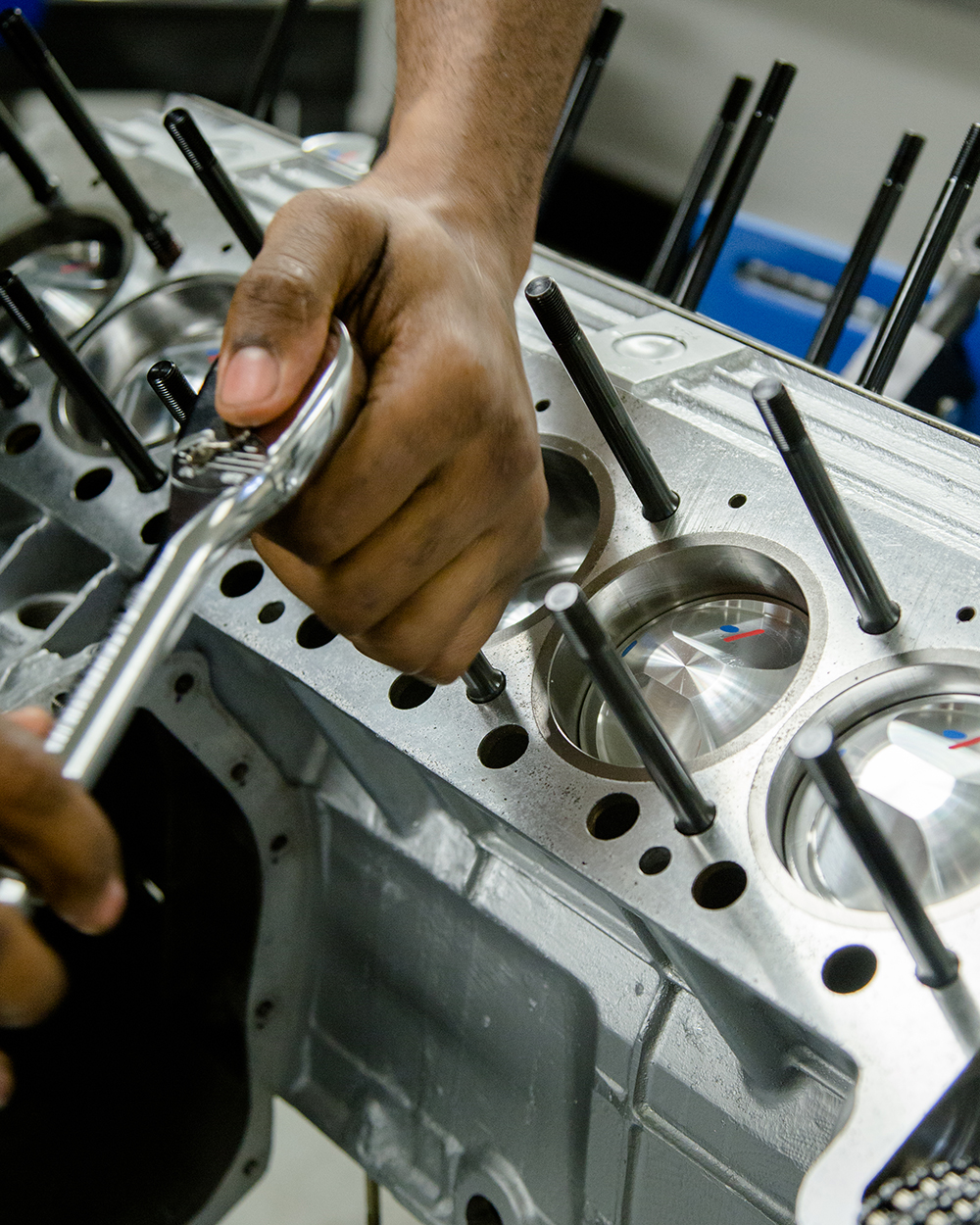
The video and photos show Darien
installing the pistons and rods to the block.
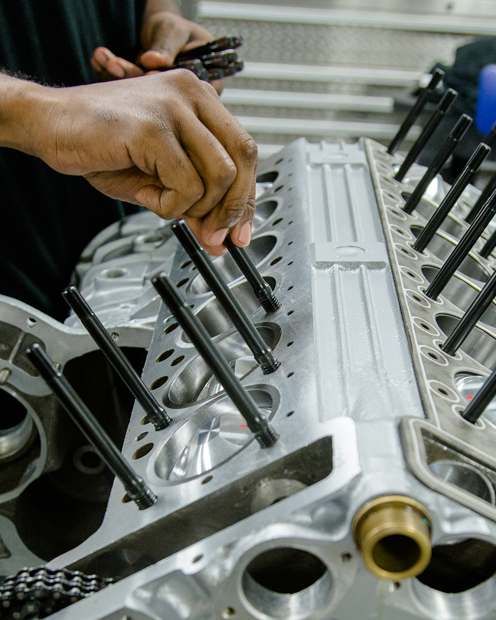
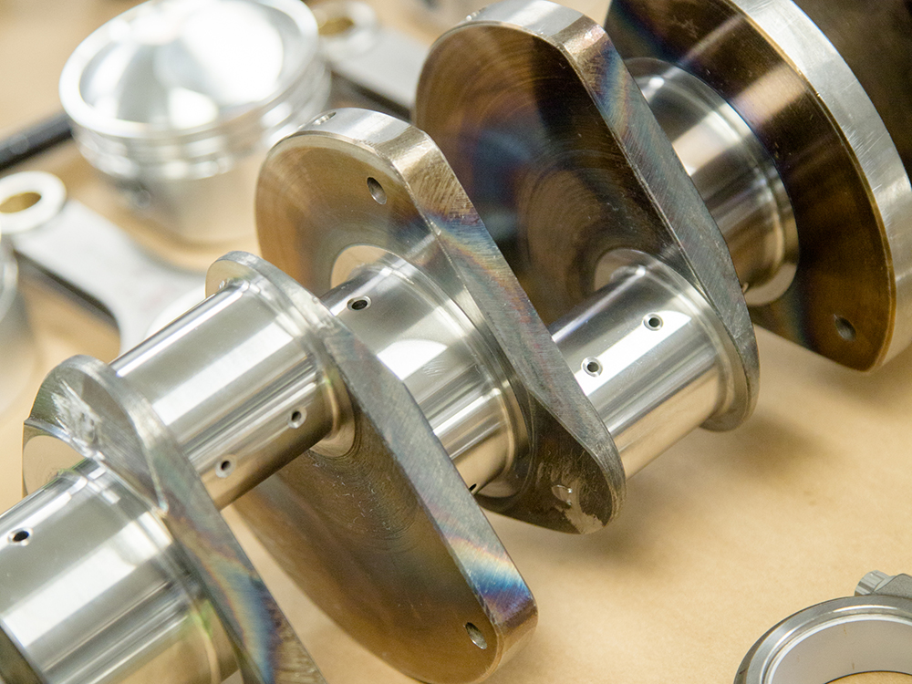
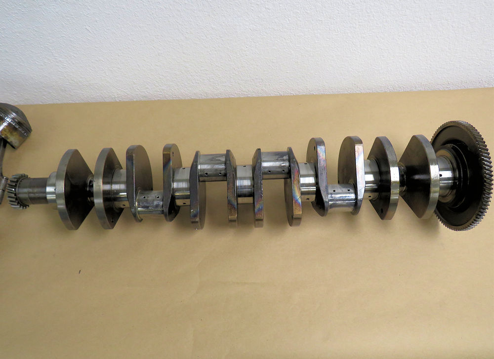
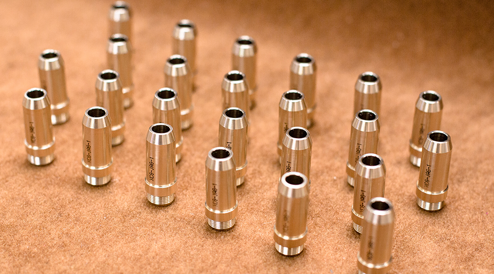
Crankshaft installed
We have our own Team CJ head studs made
for our
Lamborghini engine rebuilds
Custom FS head gaskets laid in place
Update report - December 16, 2020
Andy has been
making excellent progress with the rear chassis rail
fabrication.
Update report - December 10, 2020
Lots of
progress with the Miura in the Coachworks this week!
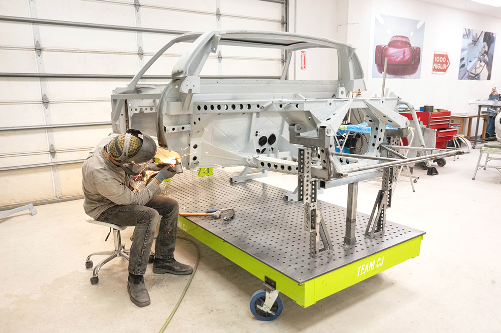
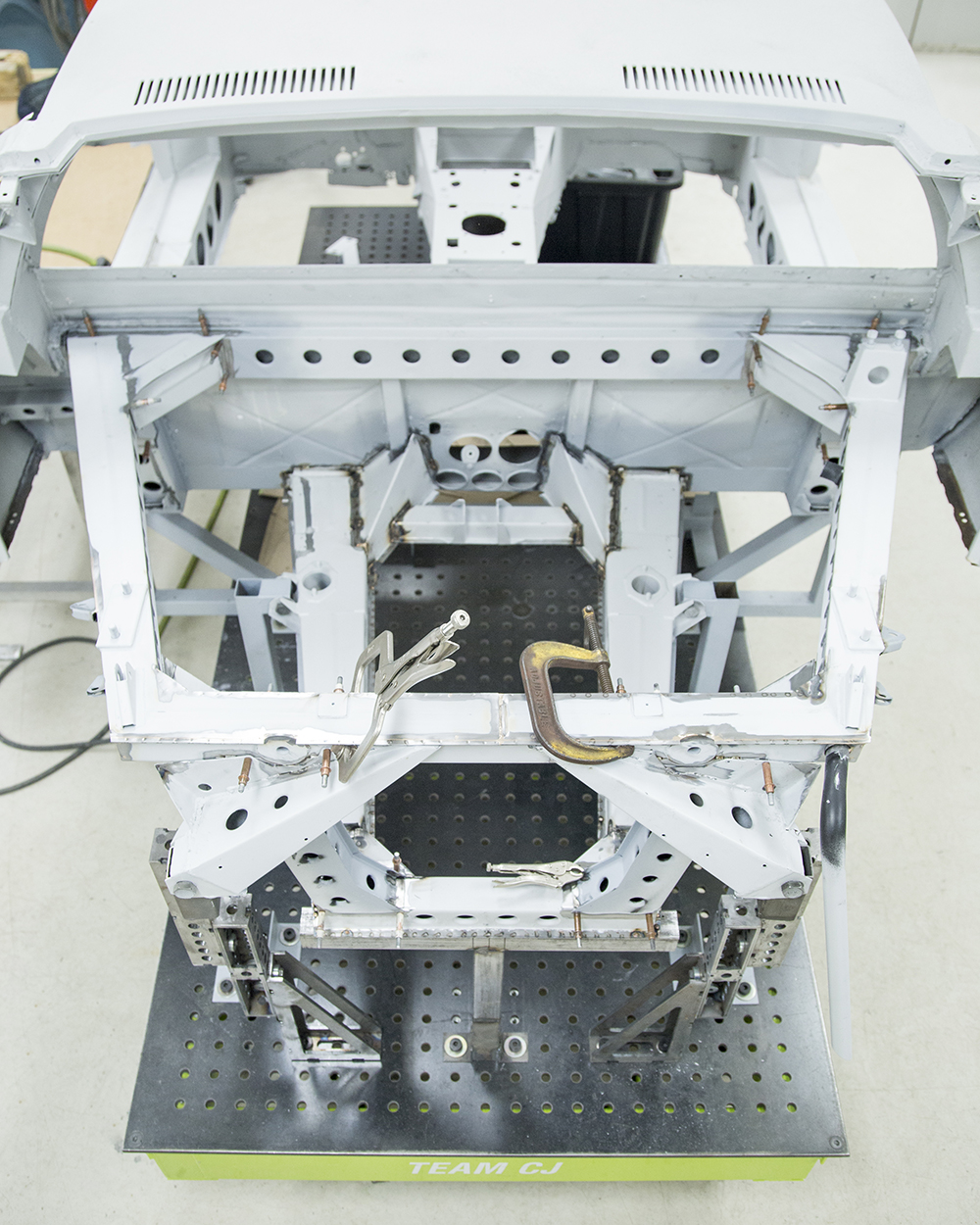
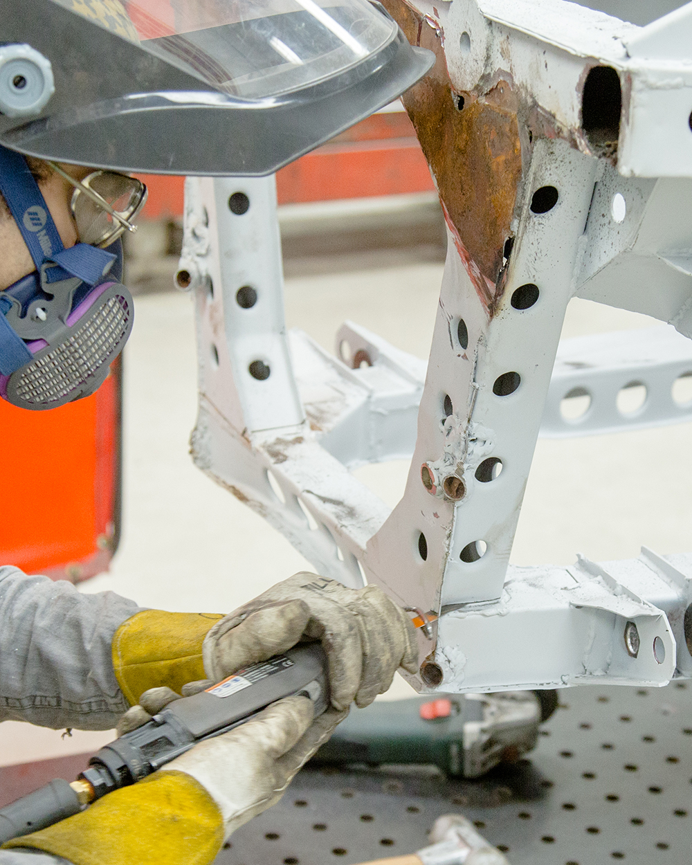
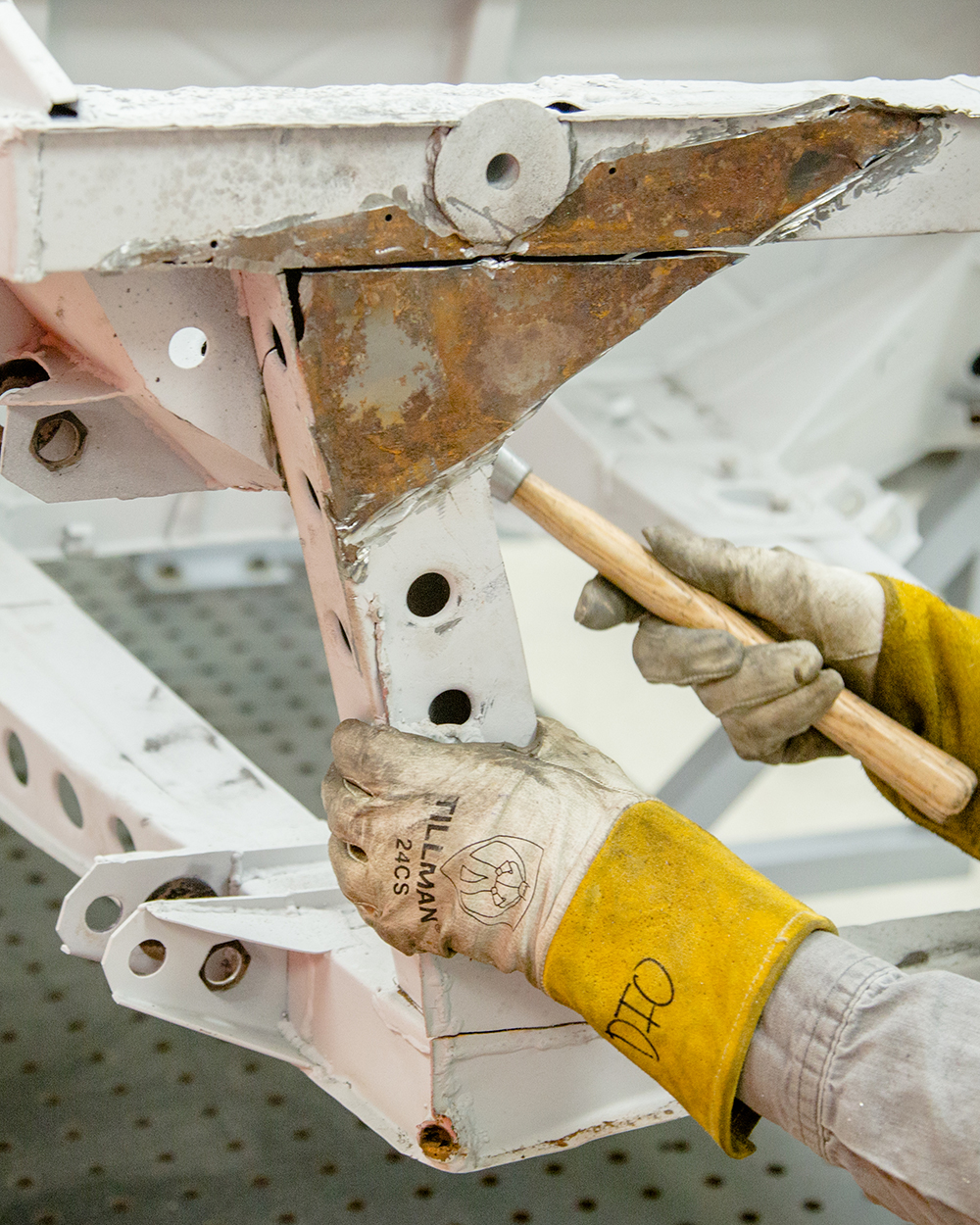
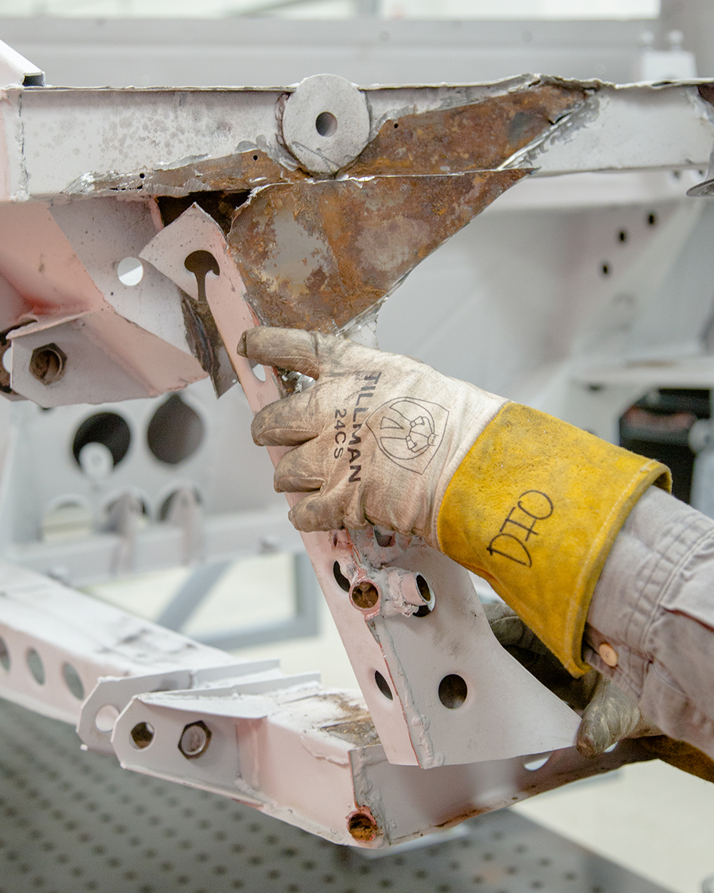
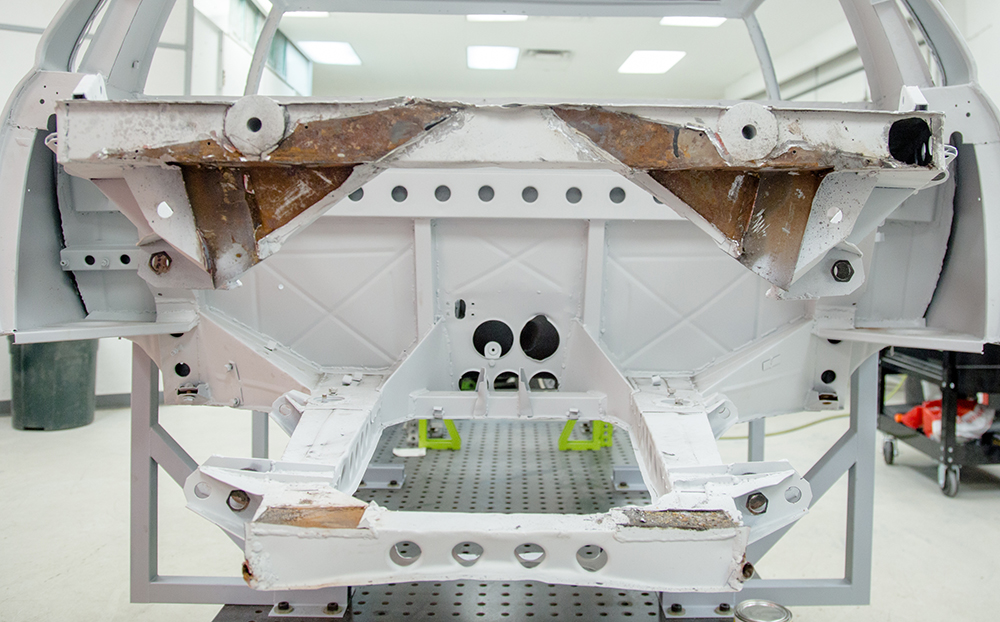
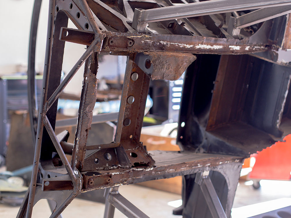
Update report - December 2, 2020
Andy is currently
tackling the repair of the rear frame rails and engine
cradle.
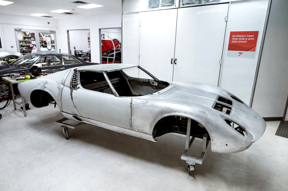
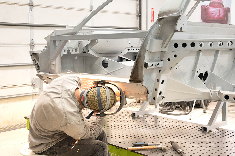
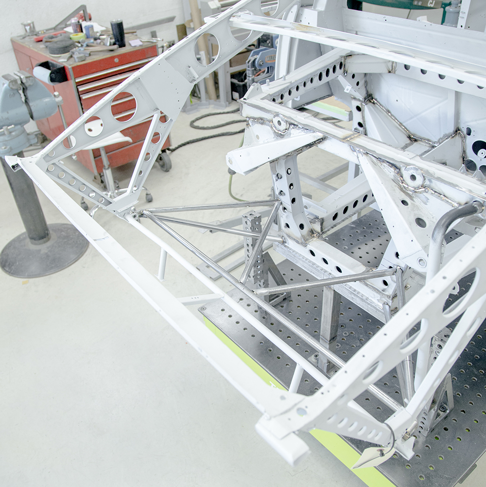
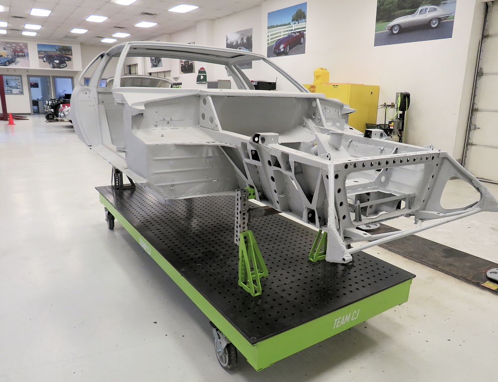
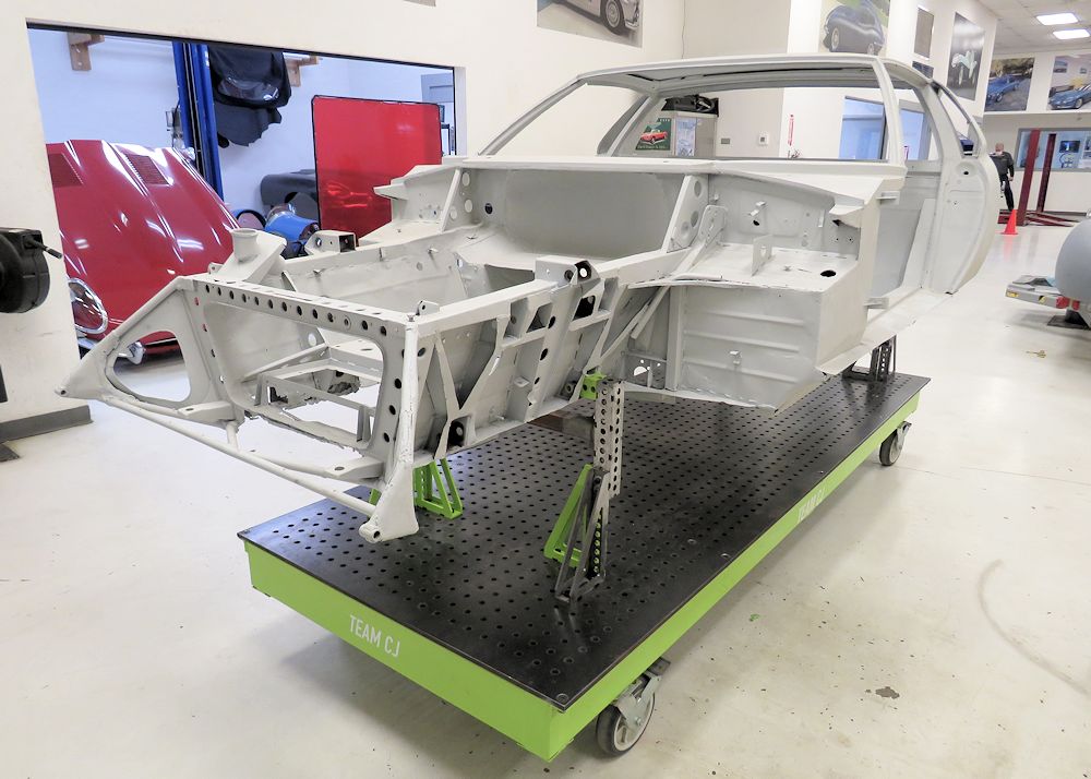
Update report - December 2, 2020
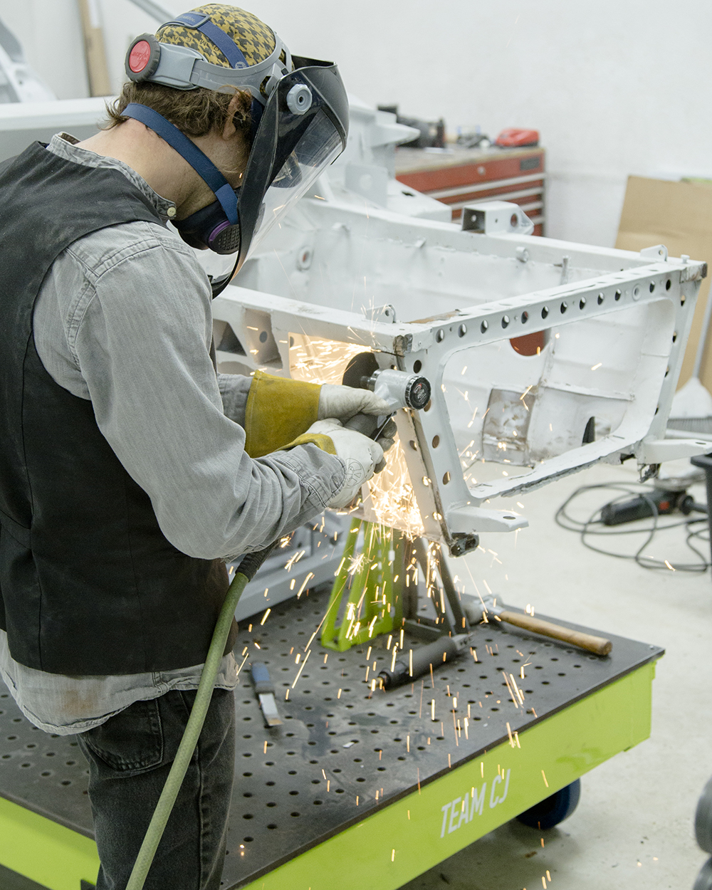
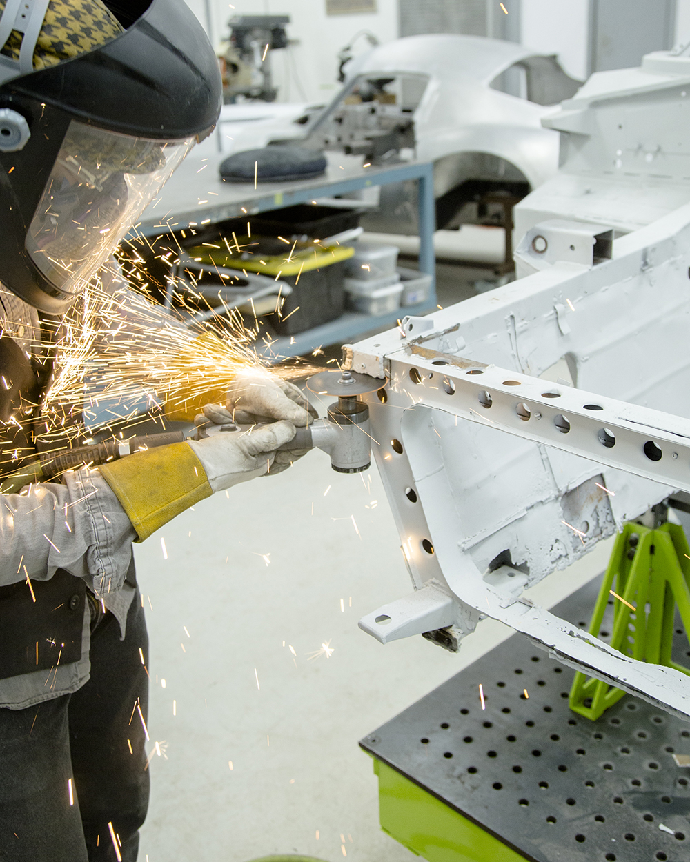
We have now begun this Miura body
restoration in earnest.
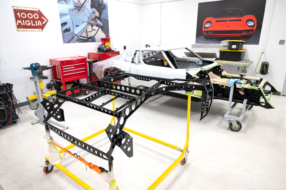
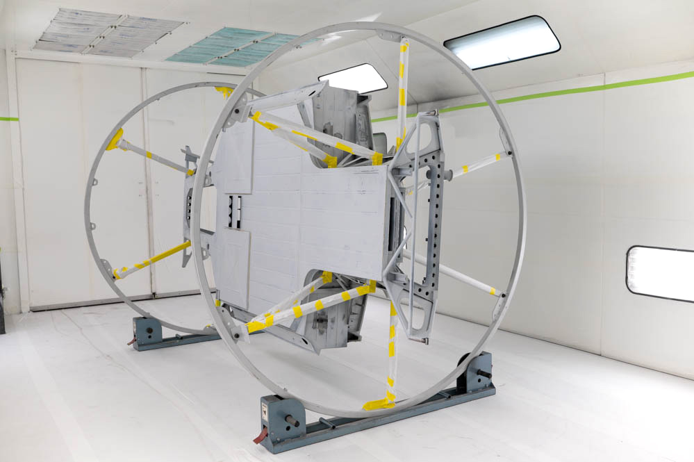
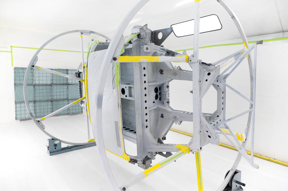
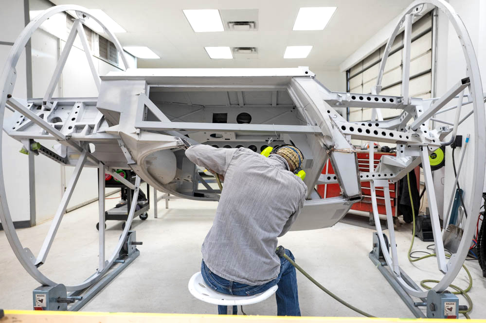
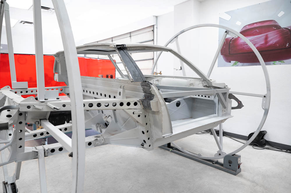
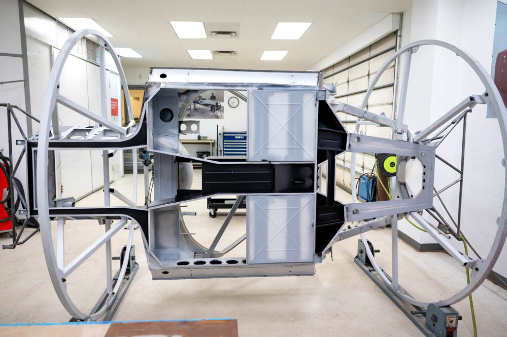
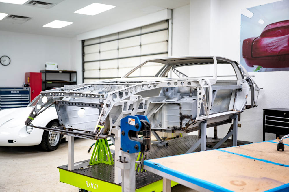
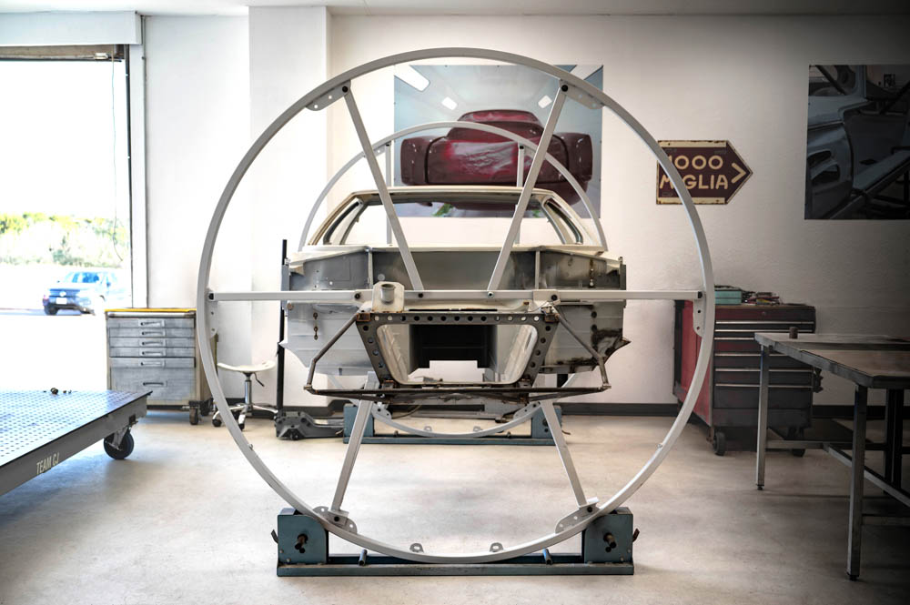
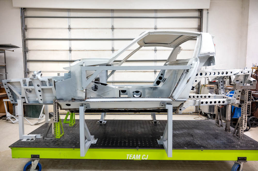
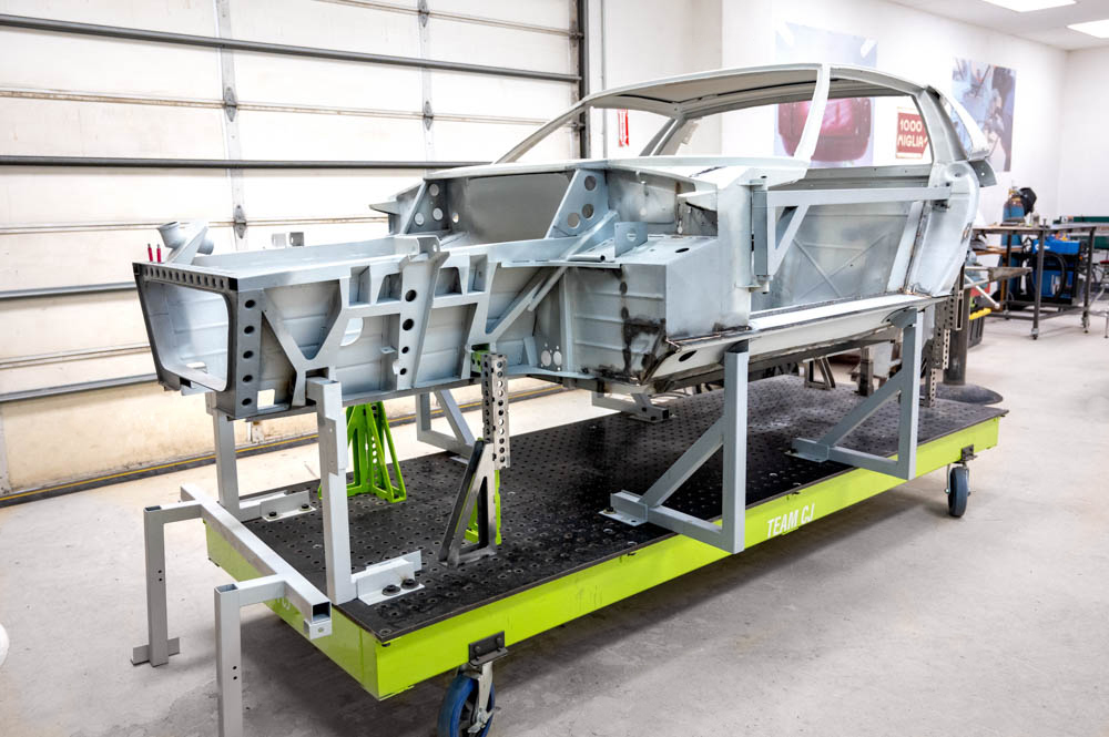
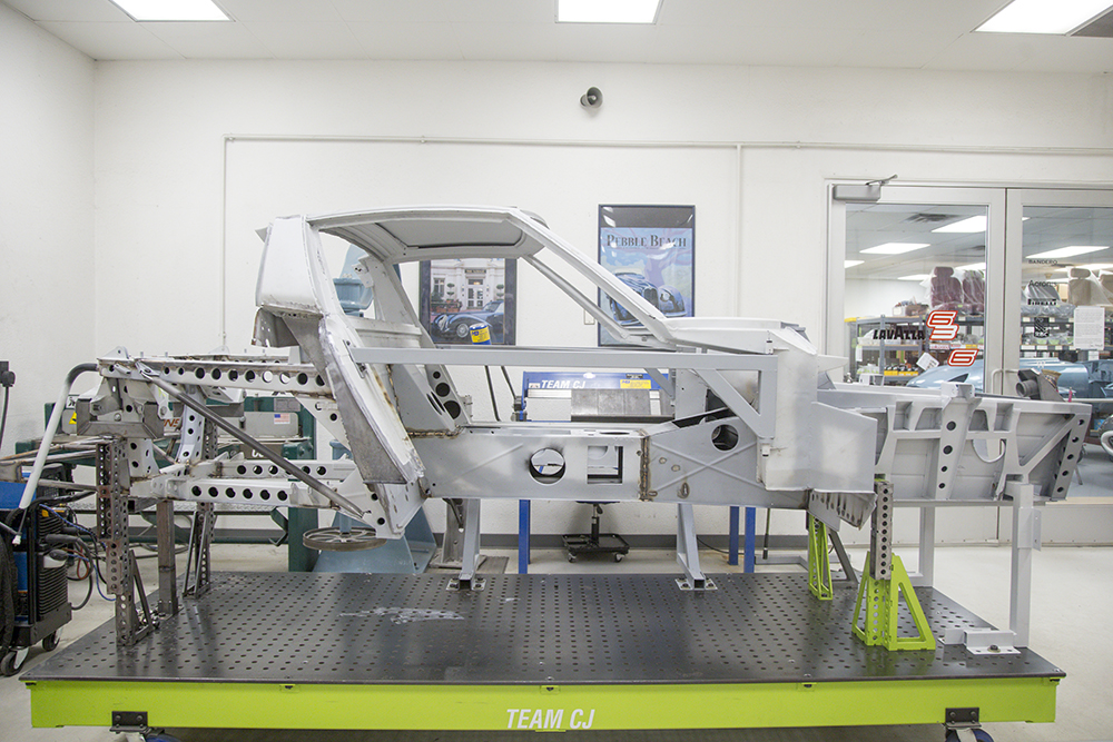
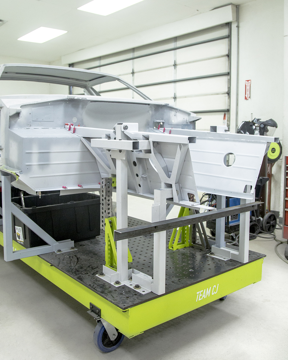
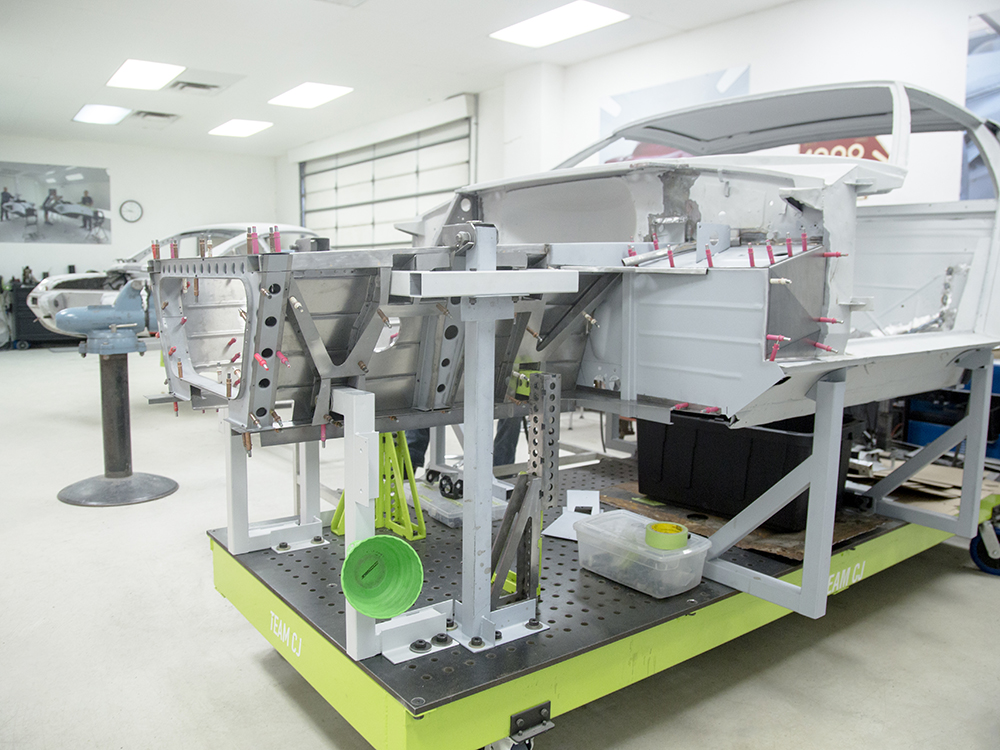
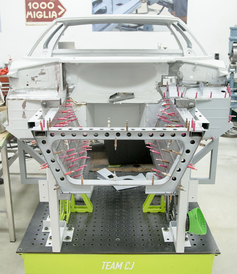
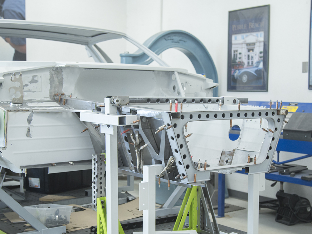
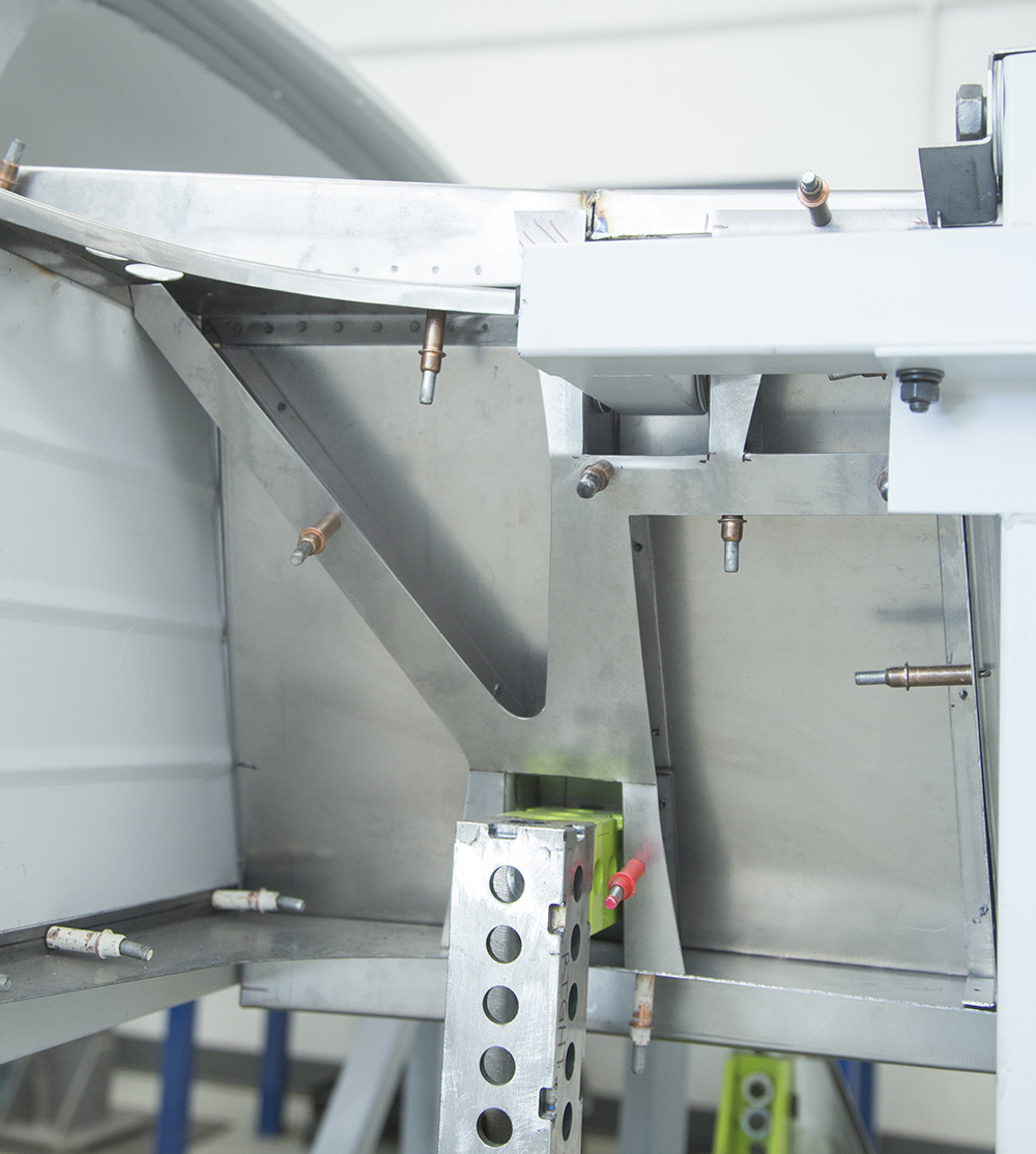
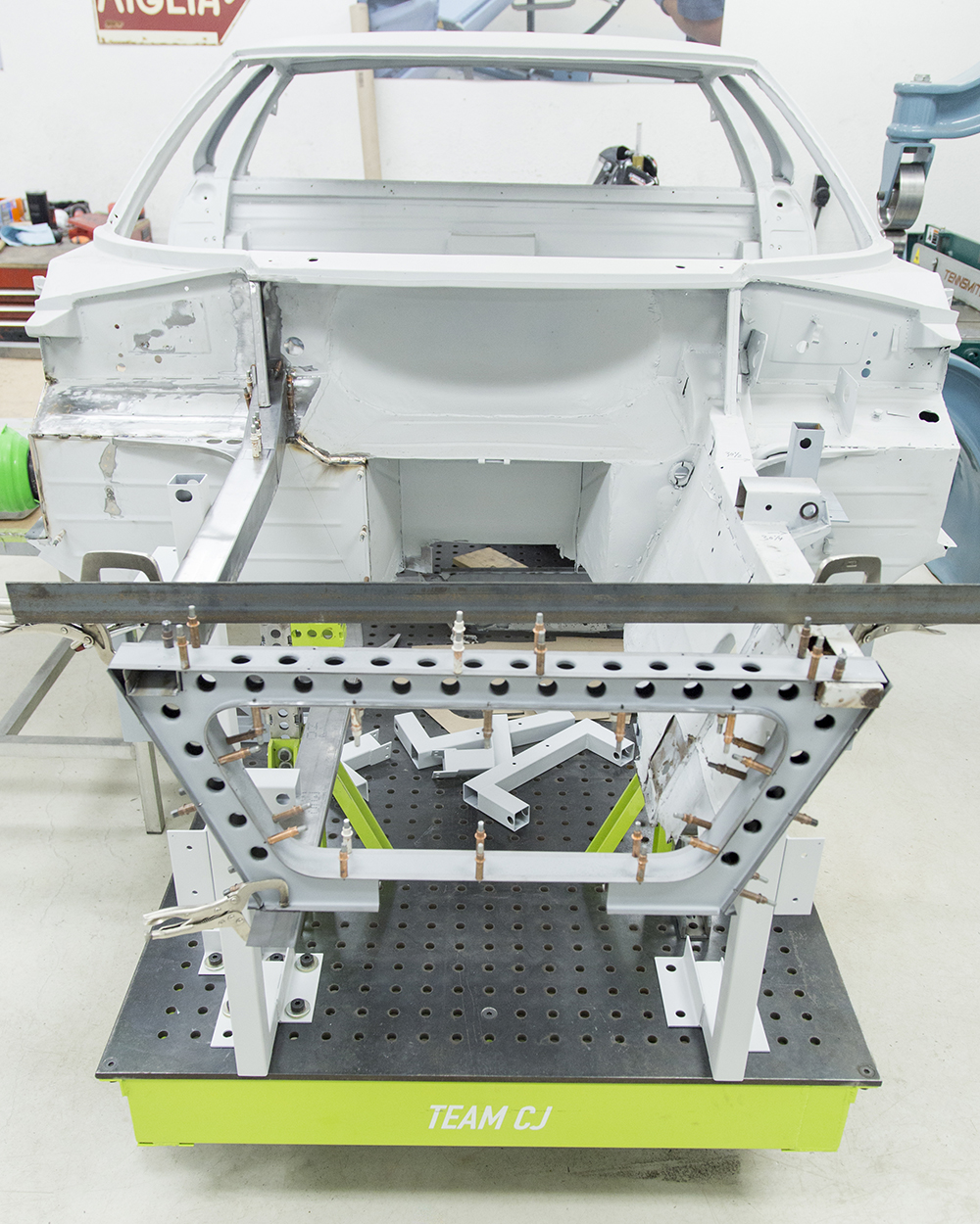
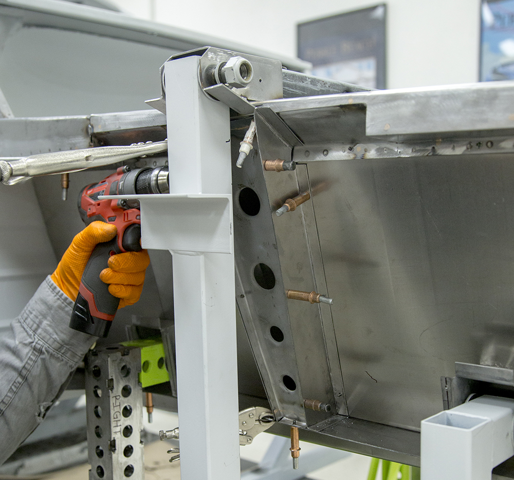
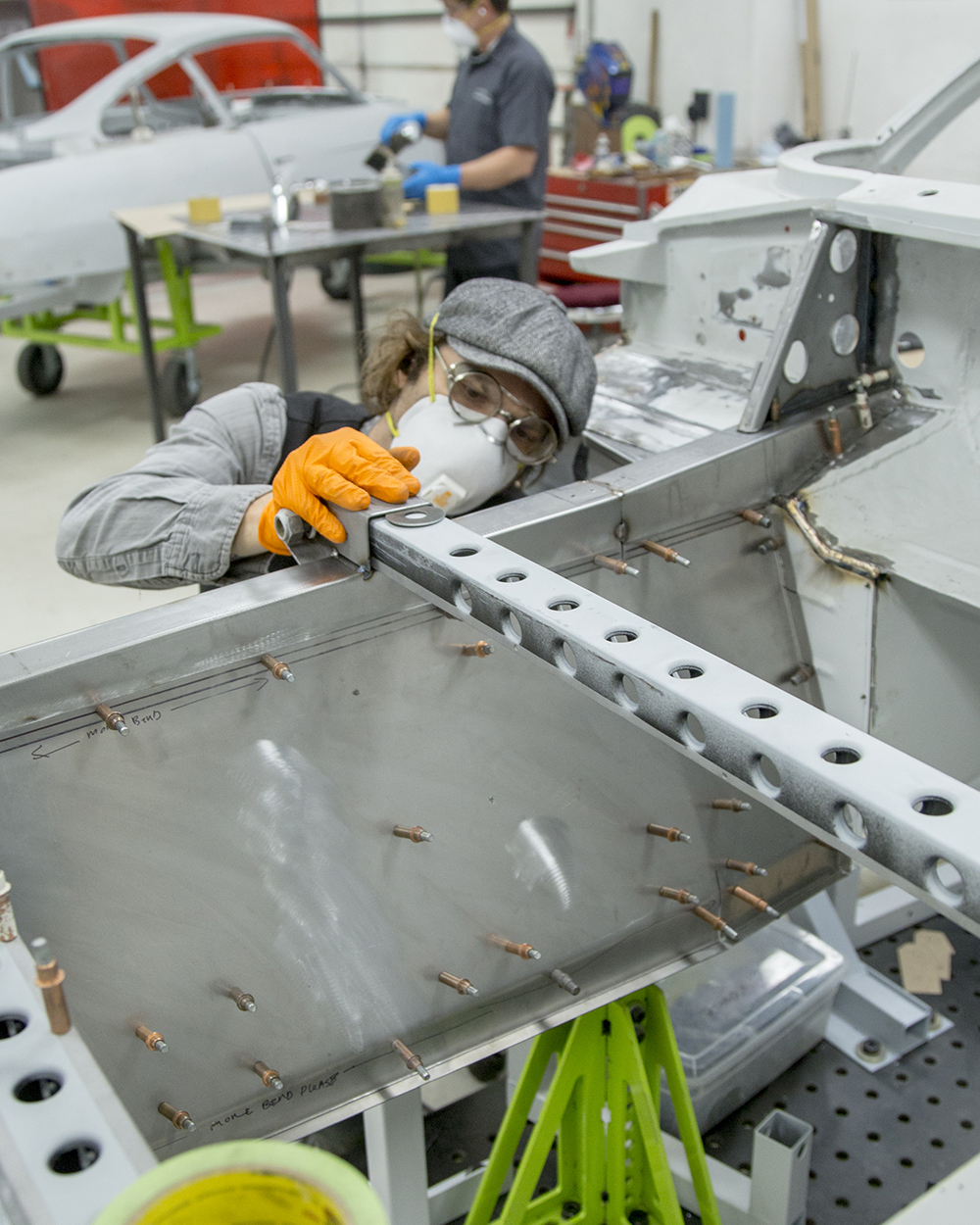
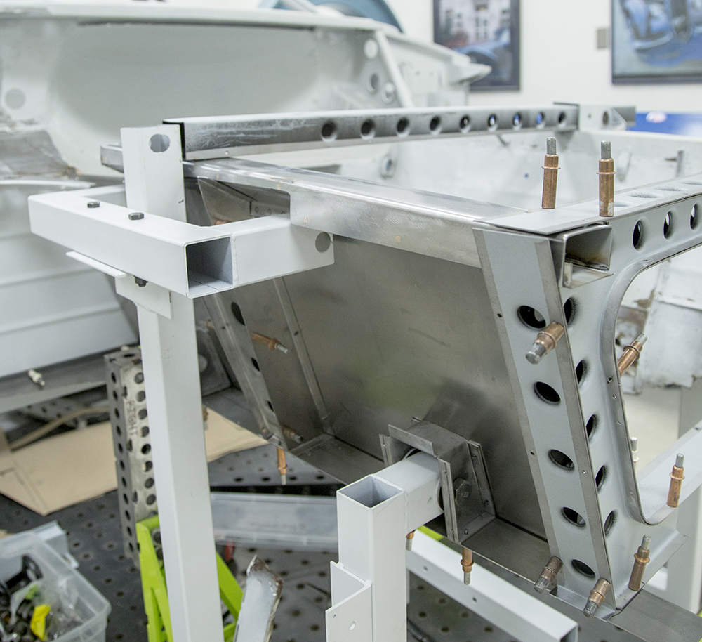
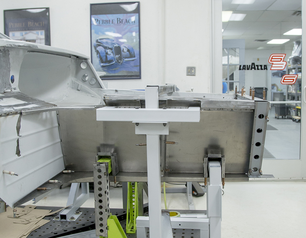
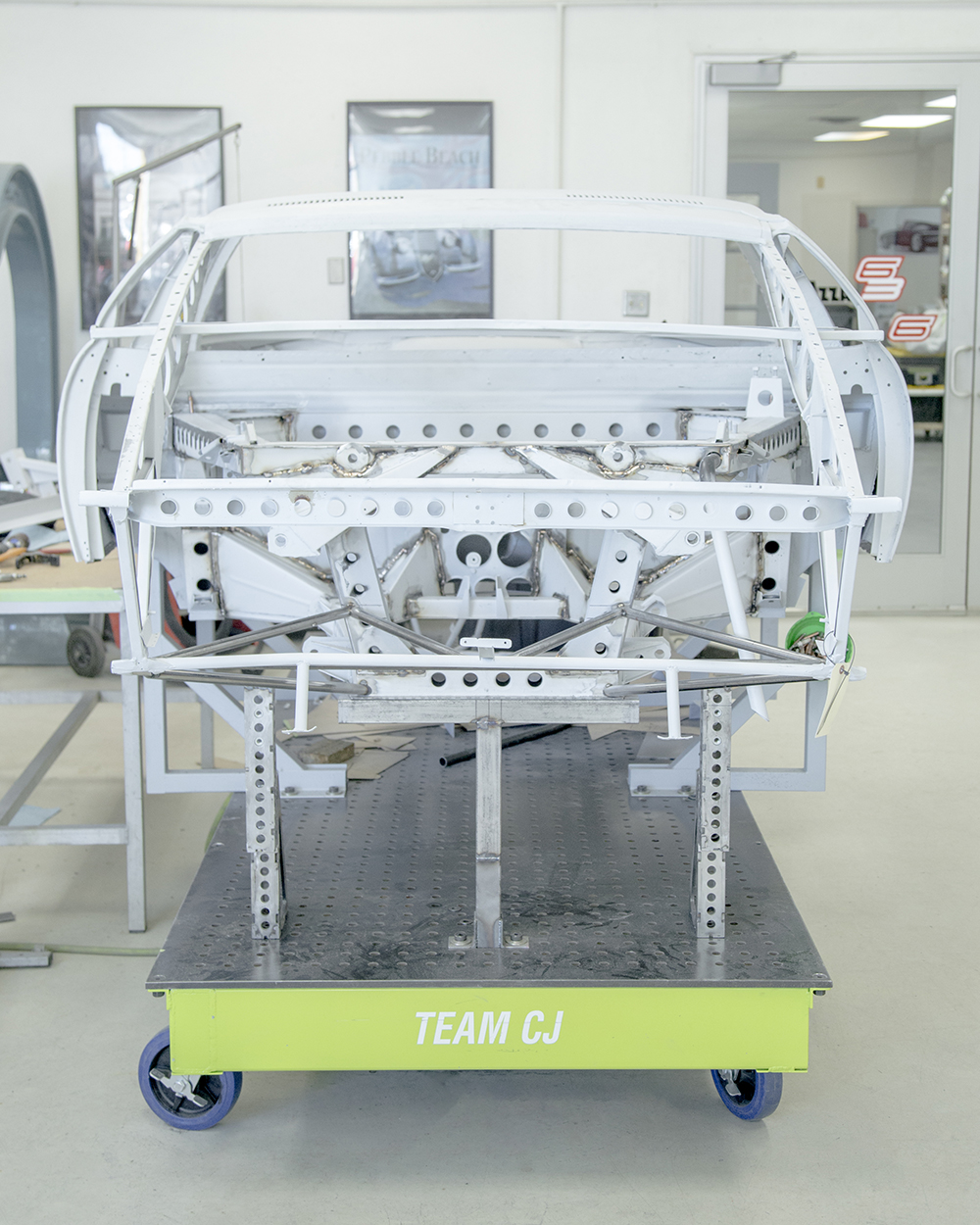
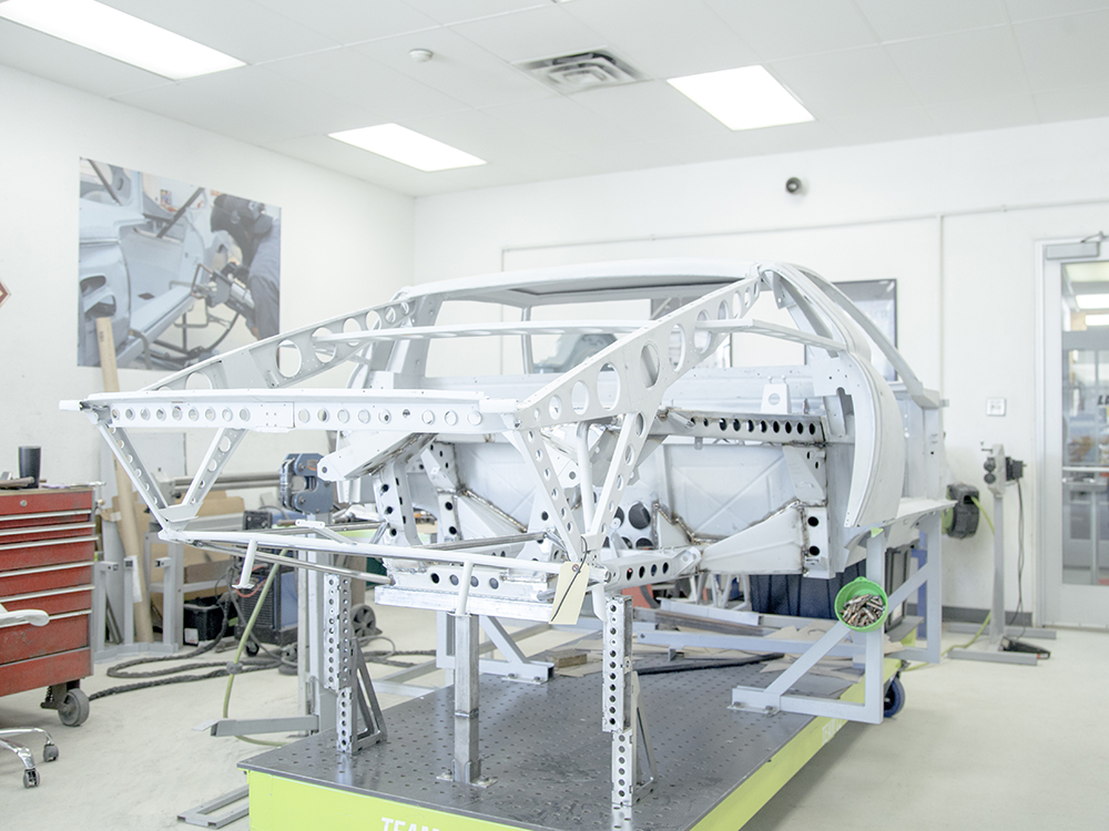
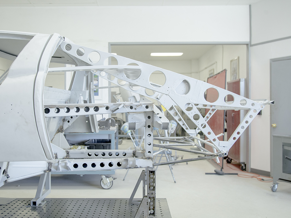
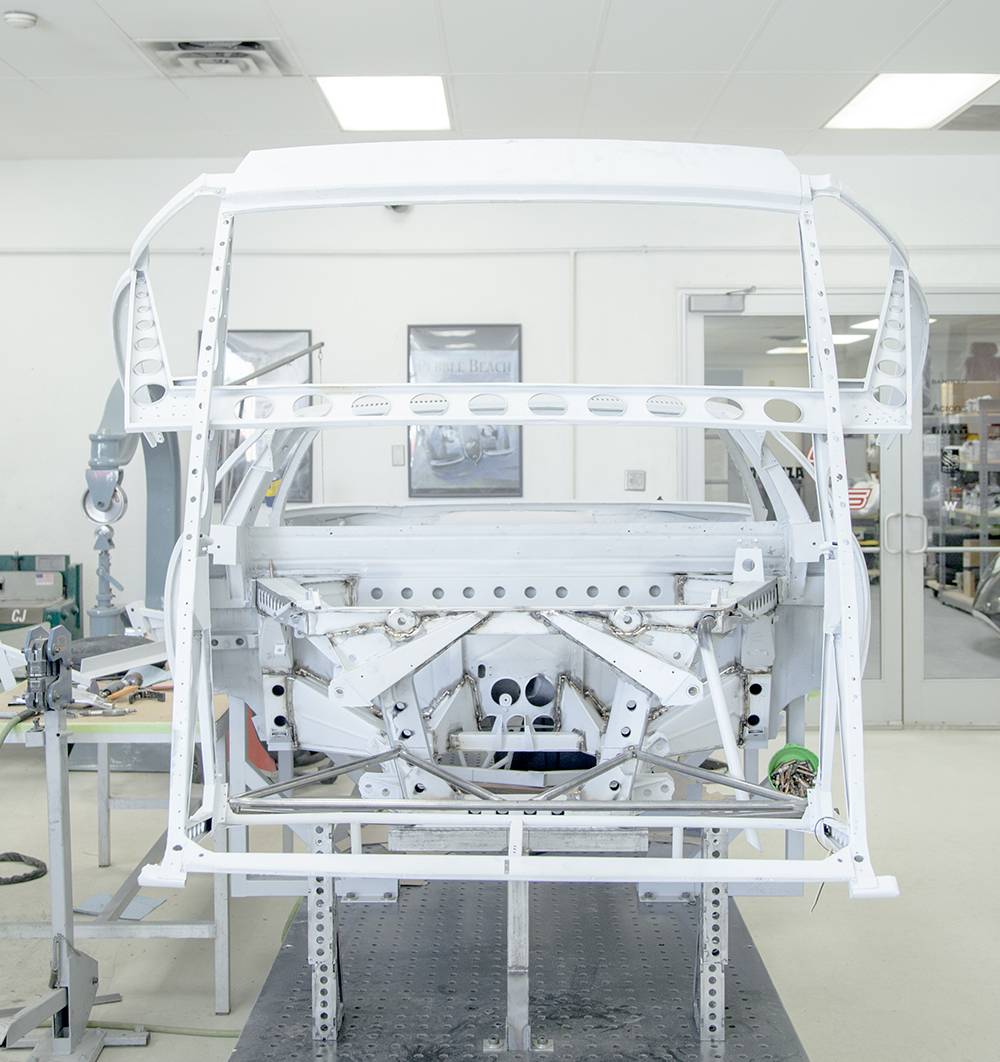
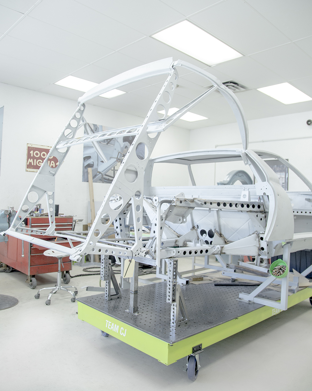
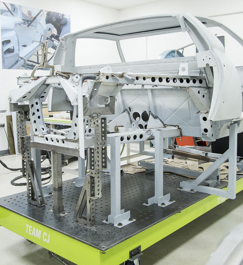
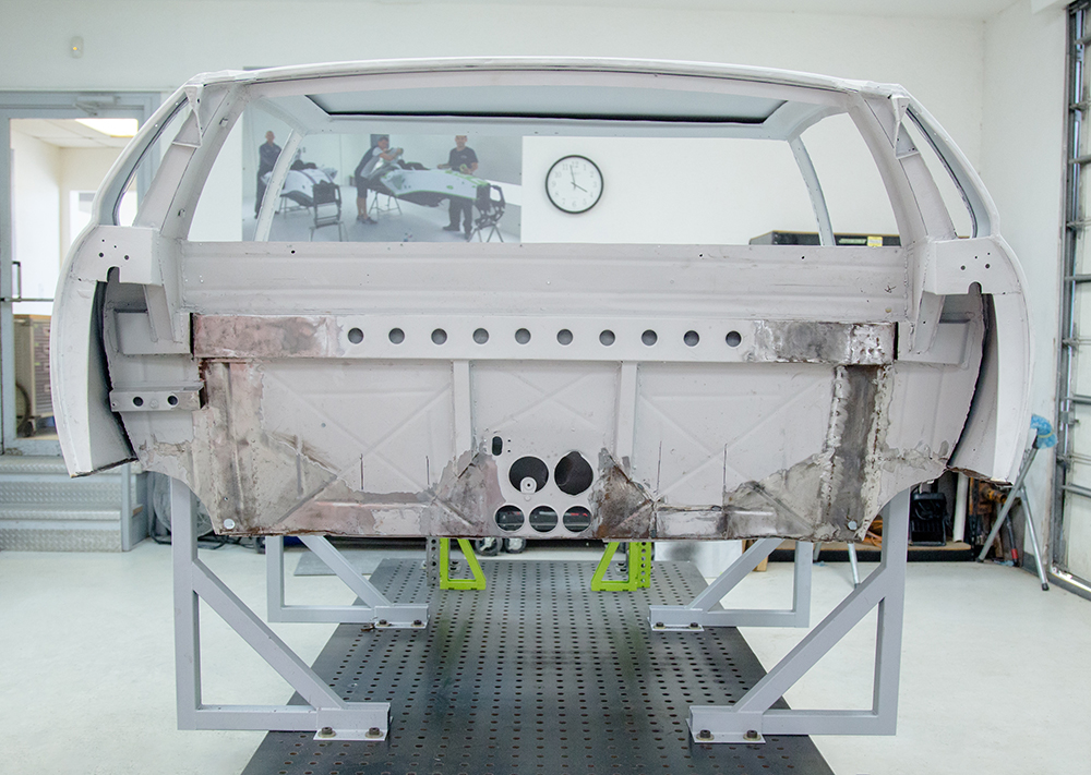
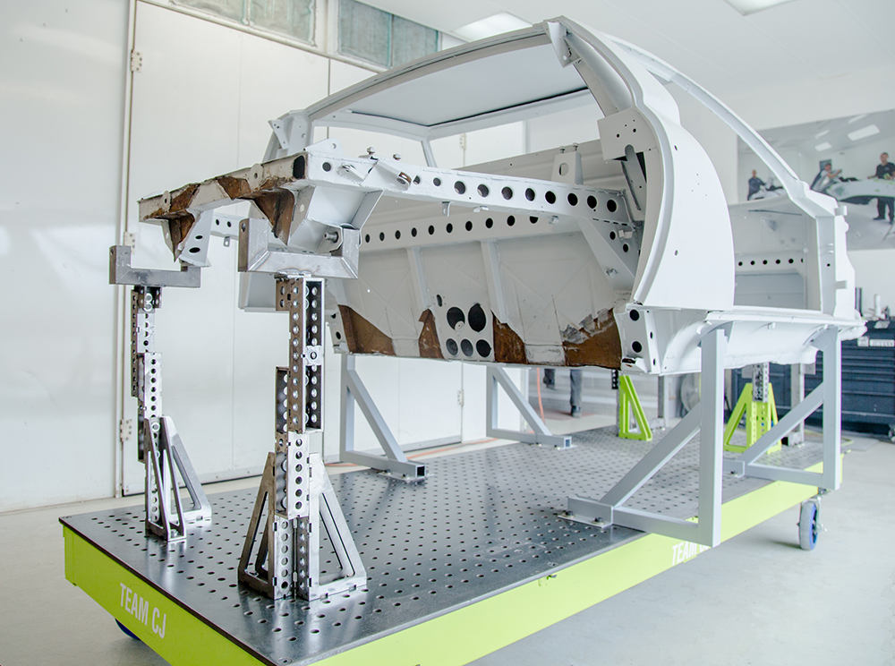
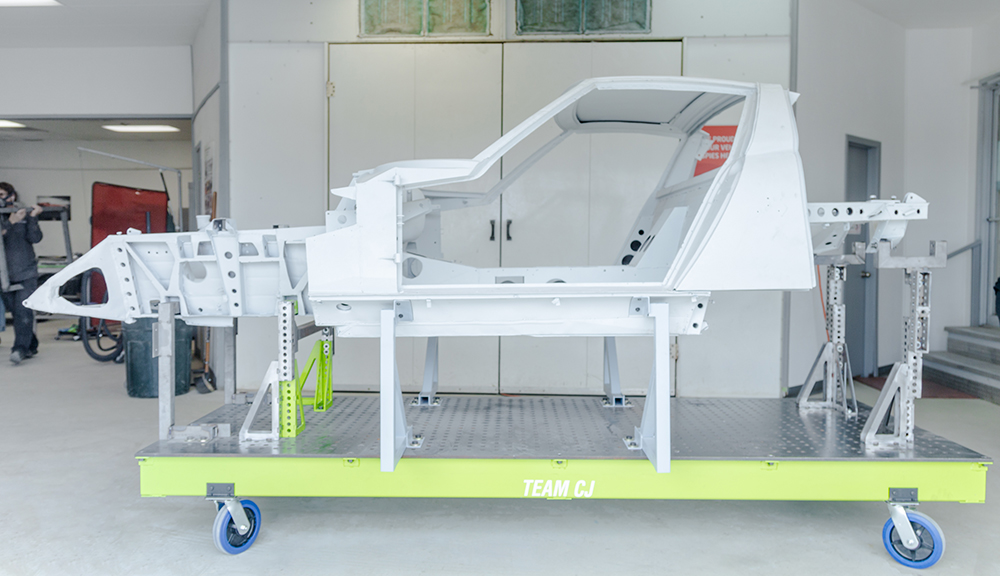
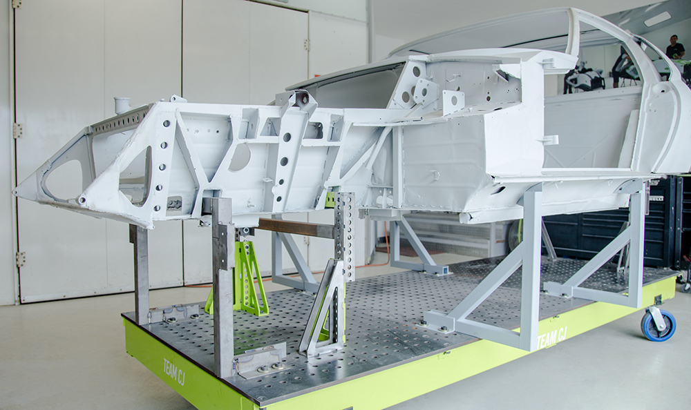
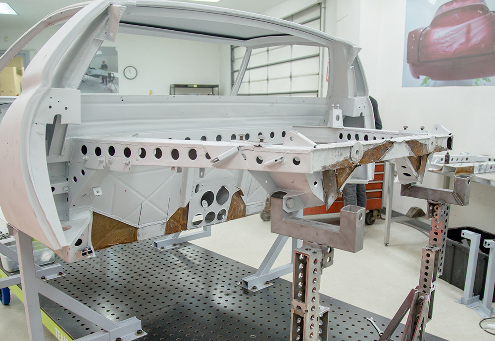
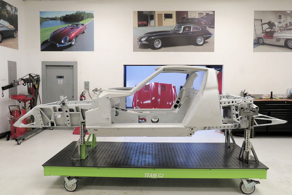
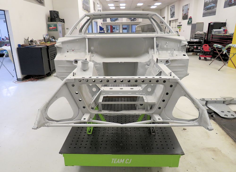
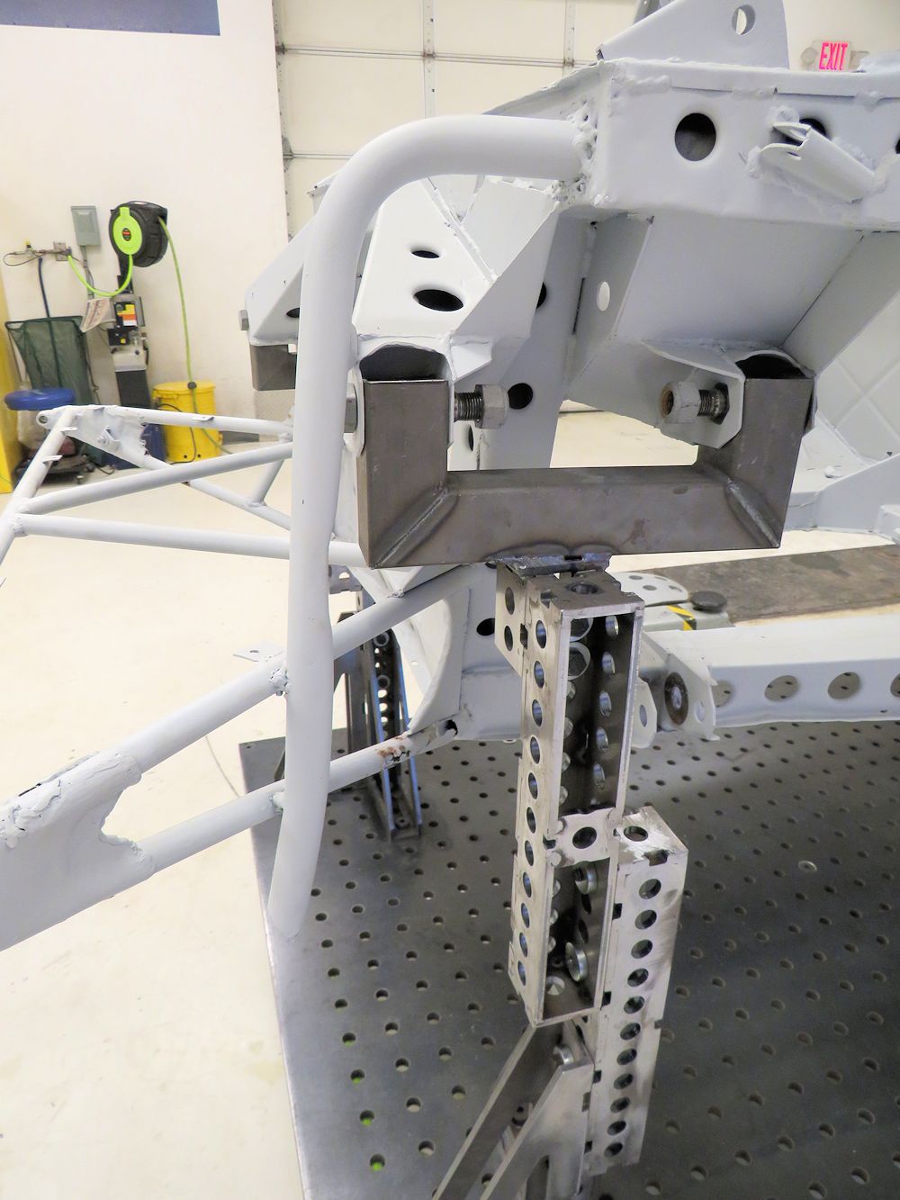
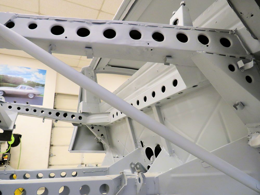
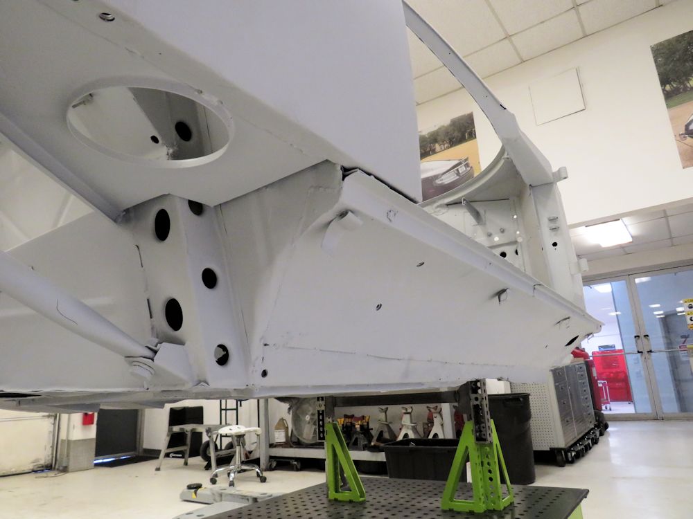
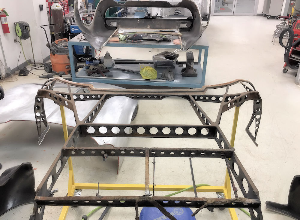
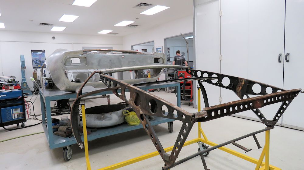
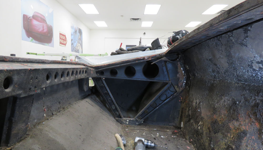
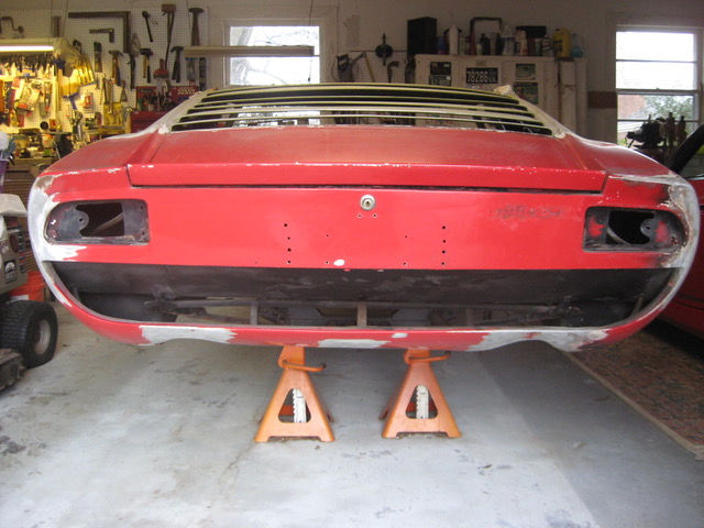
Update report - November 17, 2020
It is now time for Topo to spend some
quality time on the chassis table!
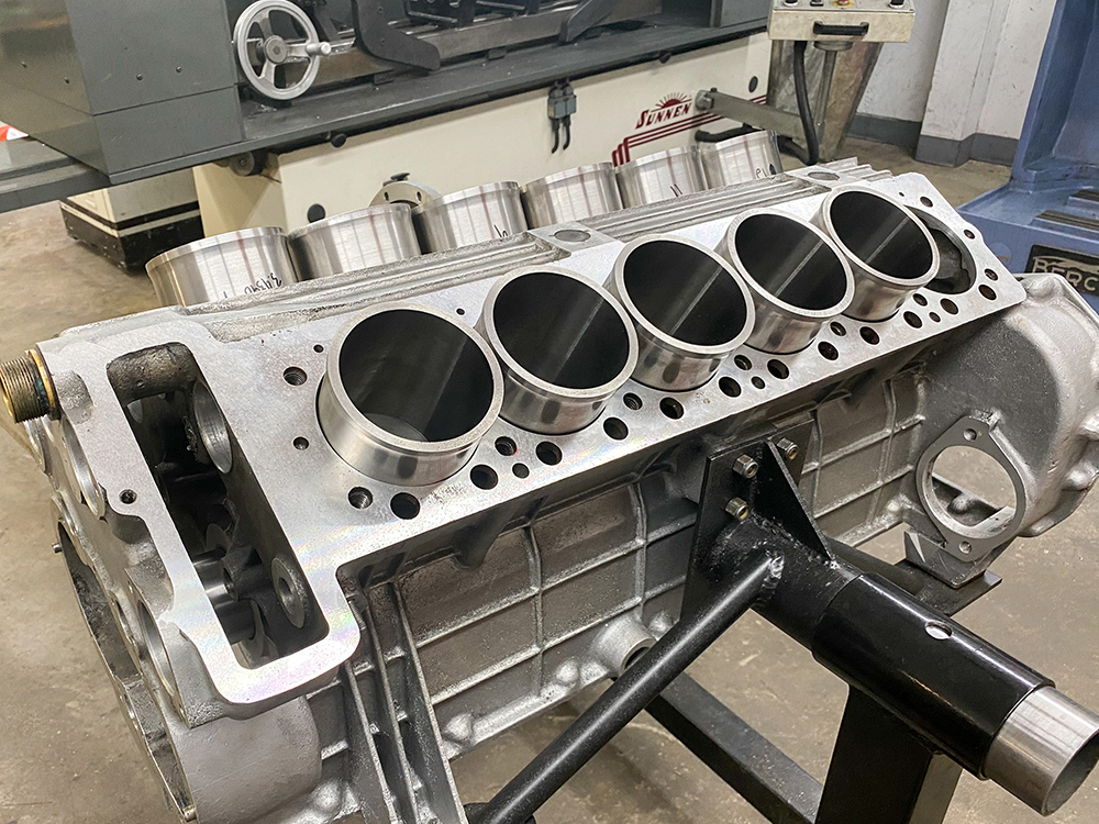
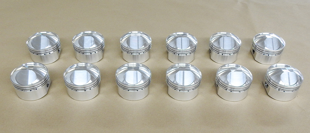
Update report - September 9, 2020
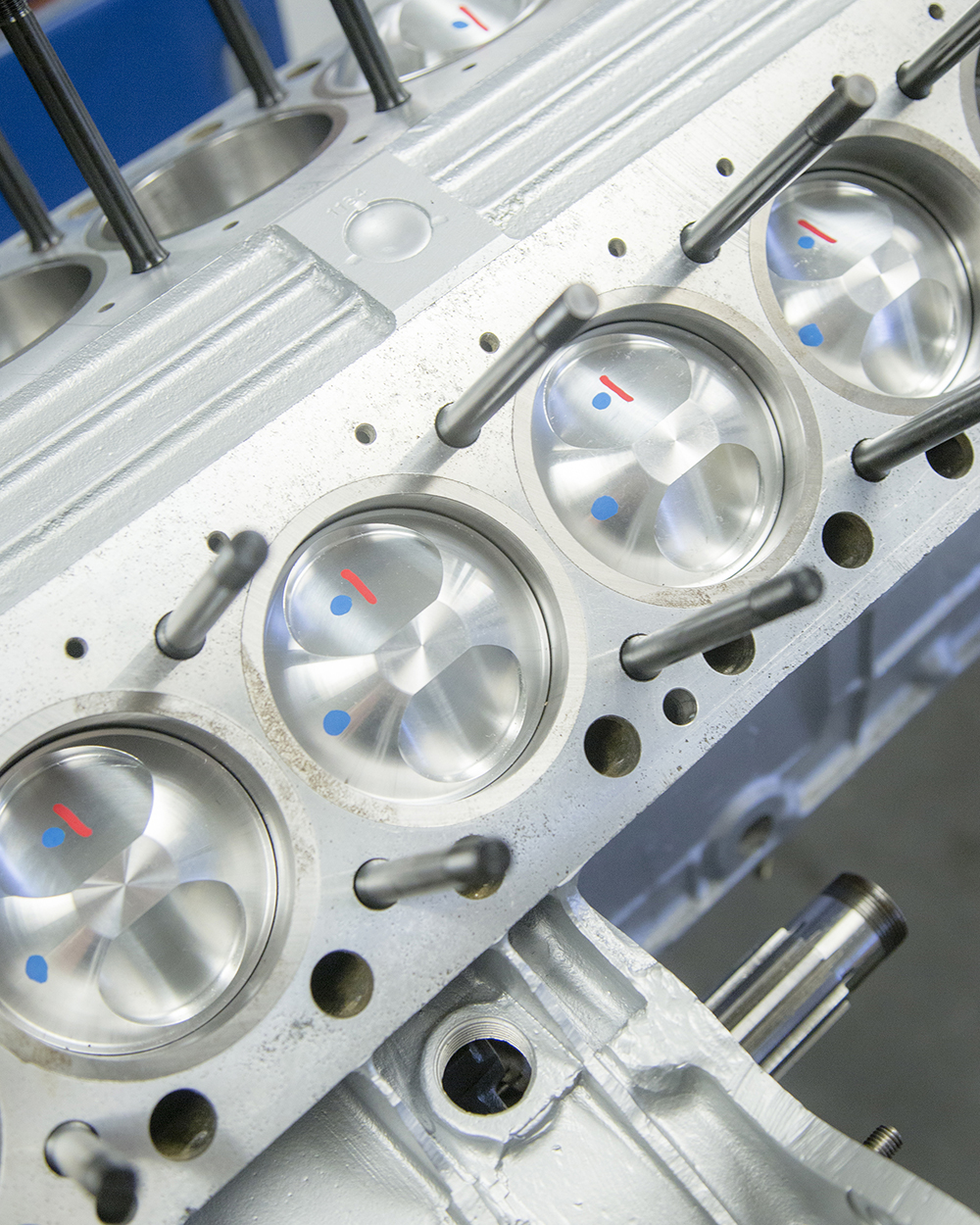
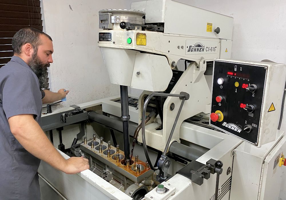
The following
images show Corey honing the new liners to size.
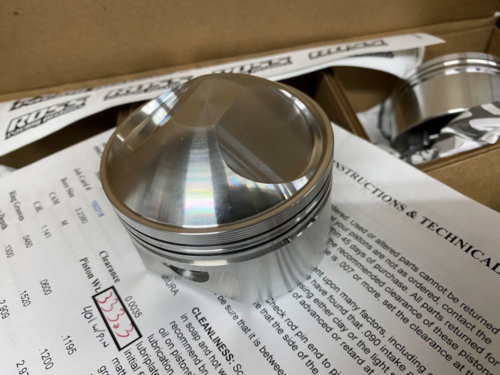
Forged pistons are installed at .0035"
clearance
Corey honing liners to size using our custom
torque plate
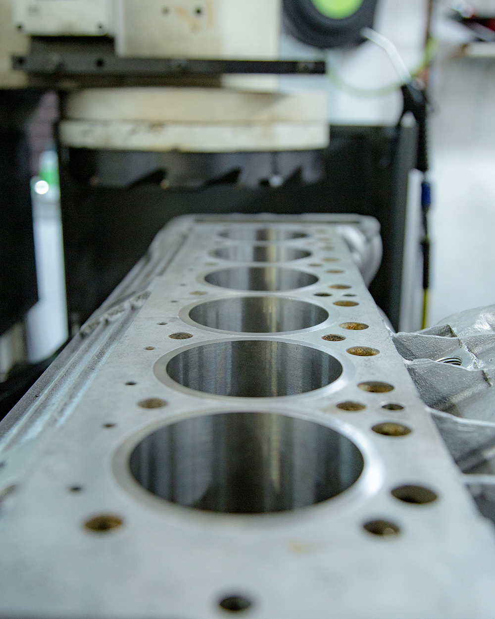
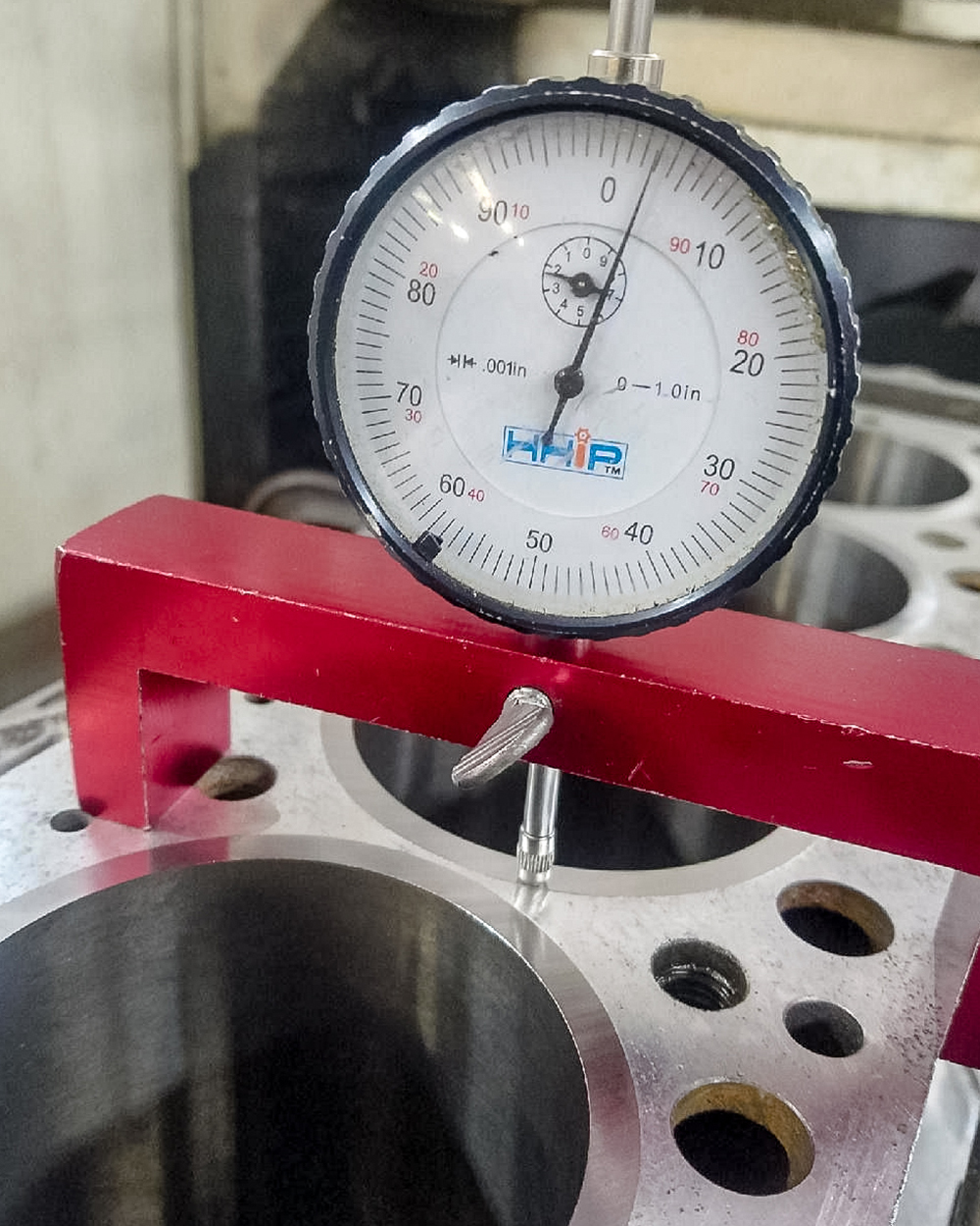
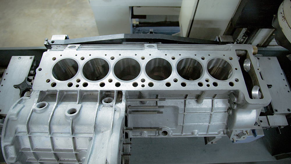
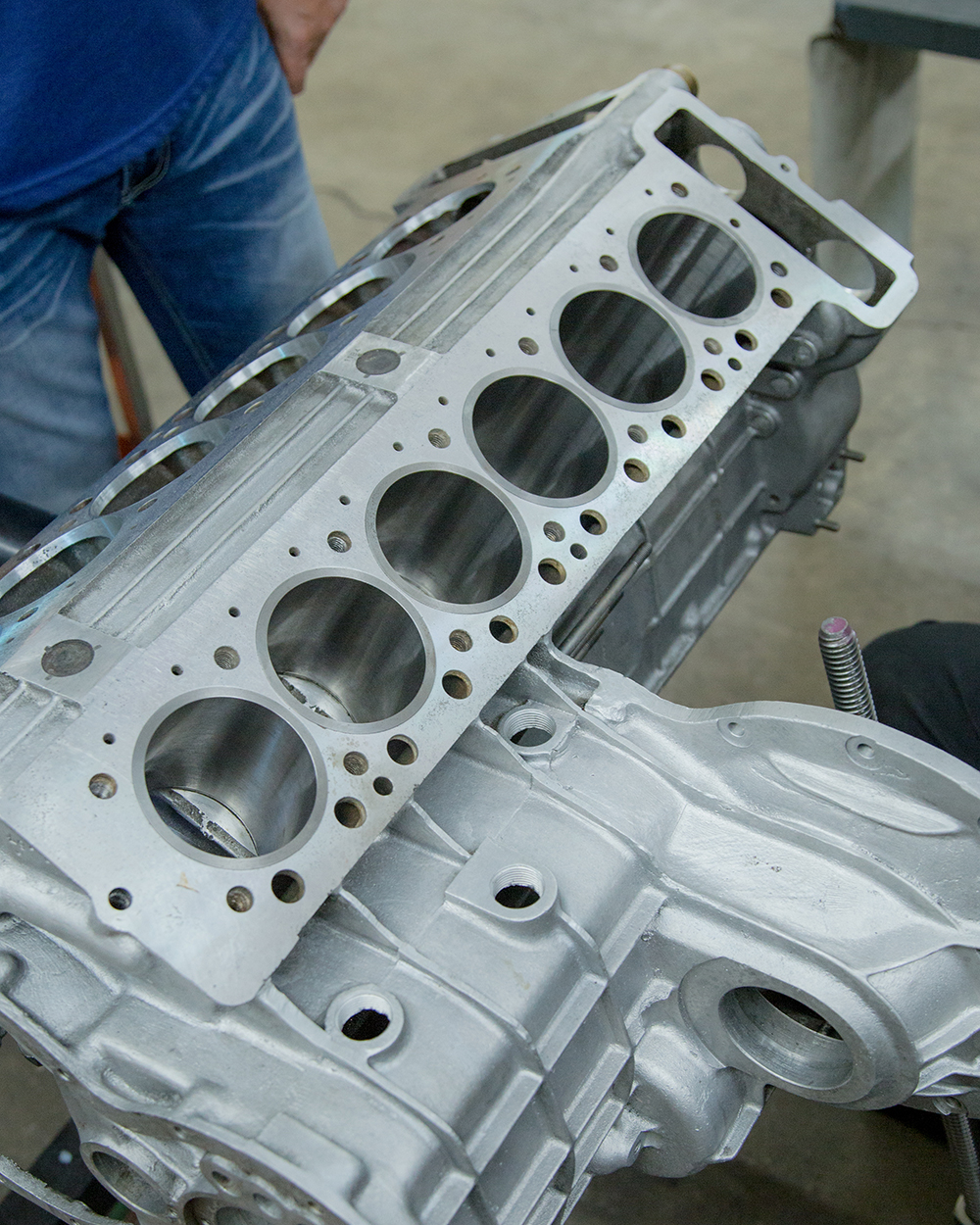
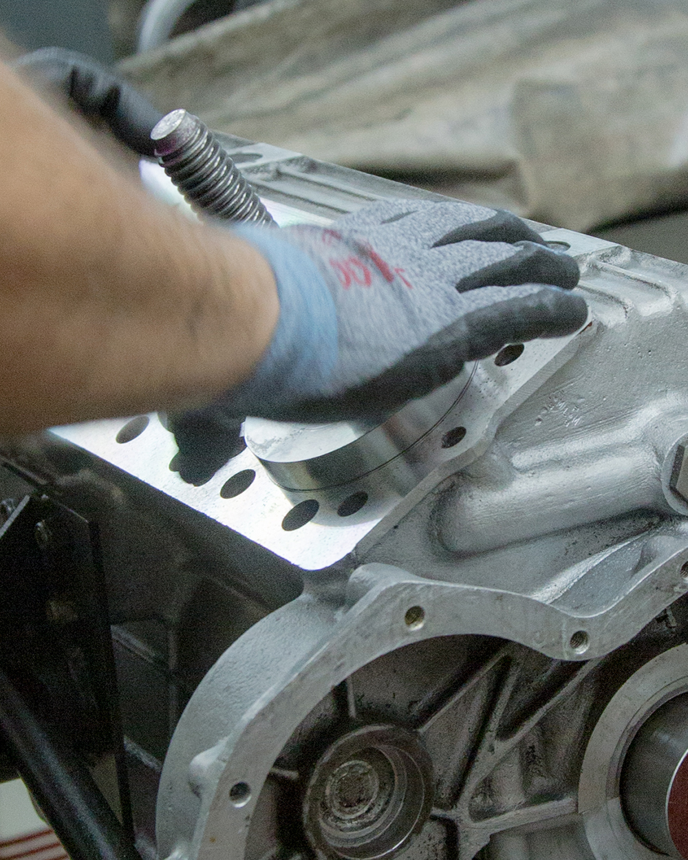
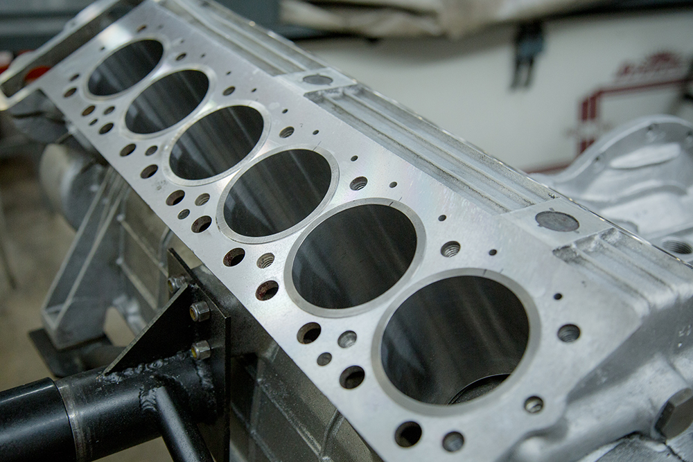
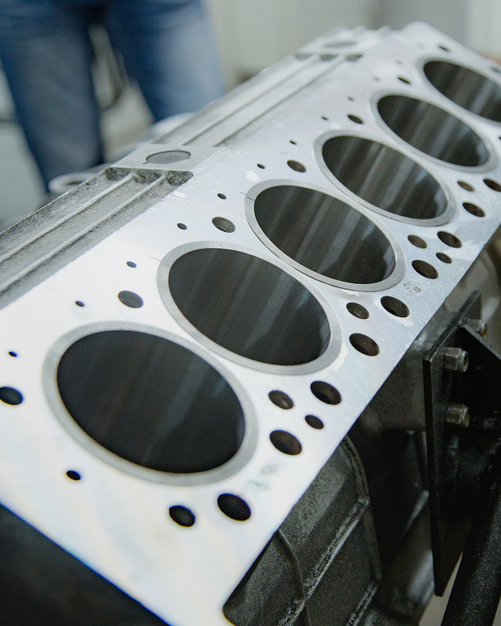
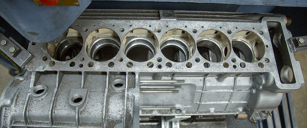
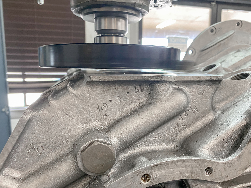
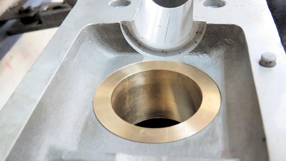
Update report - August 21, 2020
Corey has now
surfaced the tops of the liners so they are all perfectly
square and protrude above the deck precisely .003".
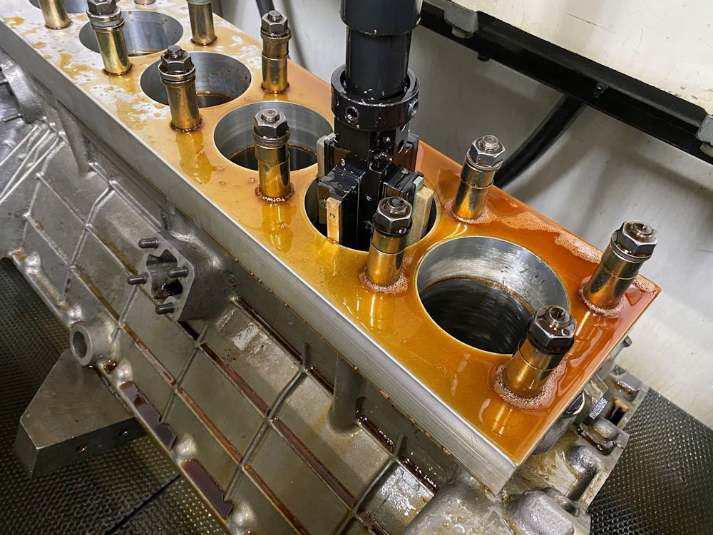
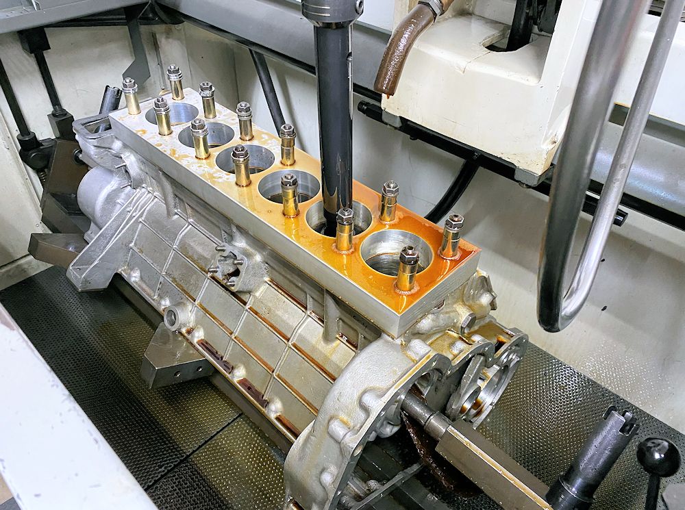
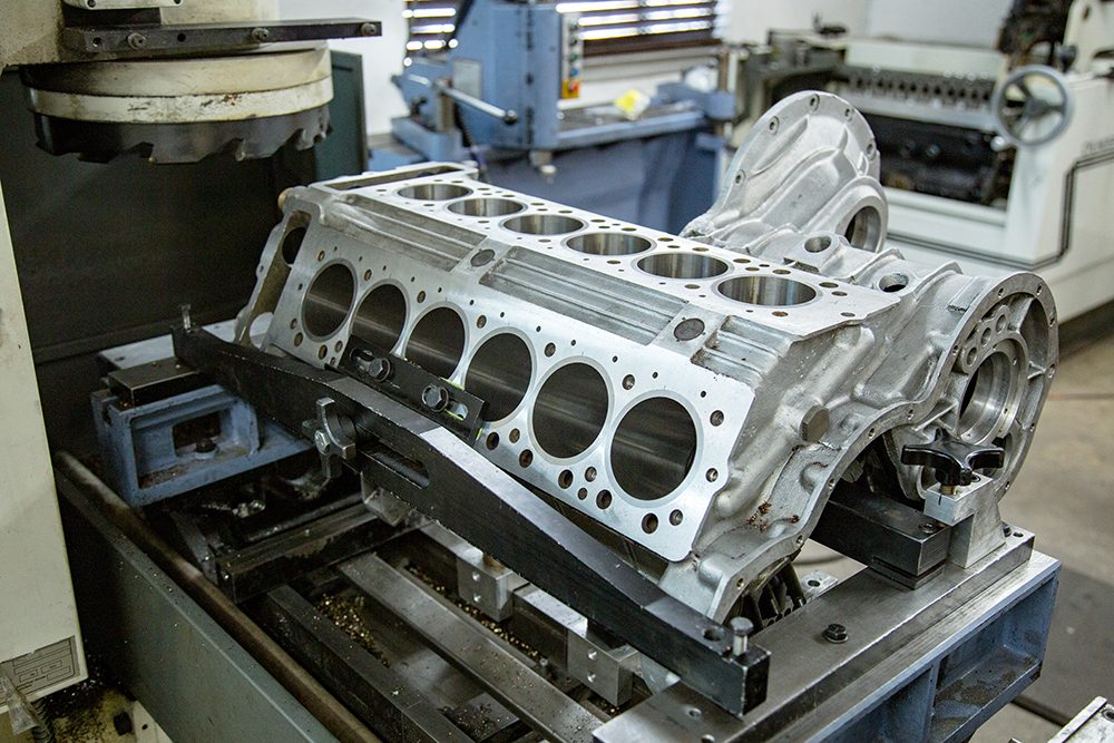
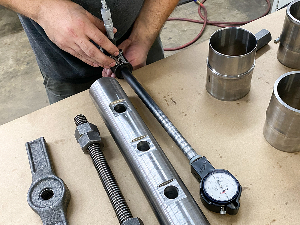
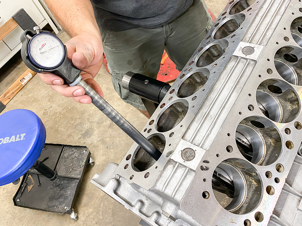
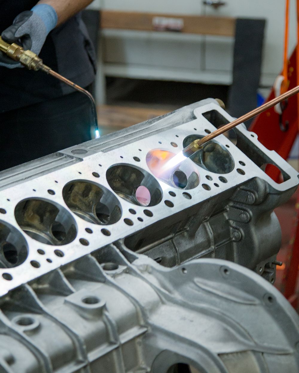
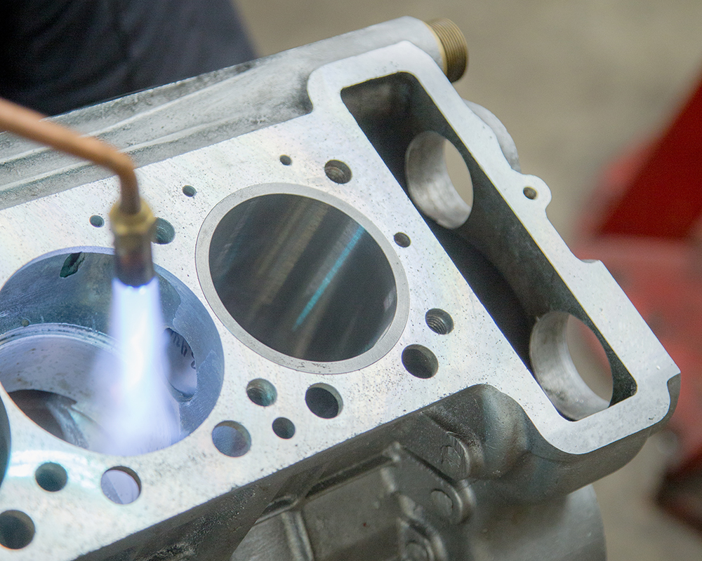
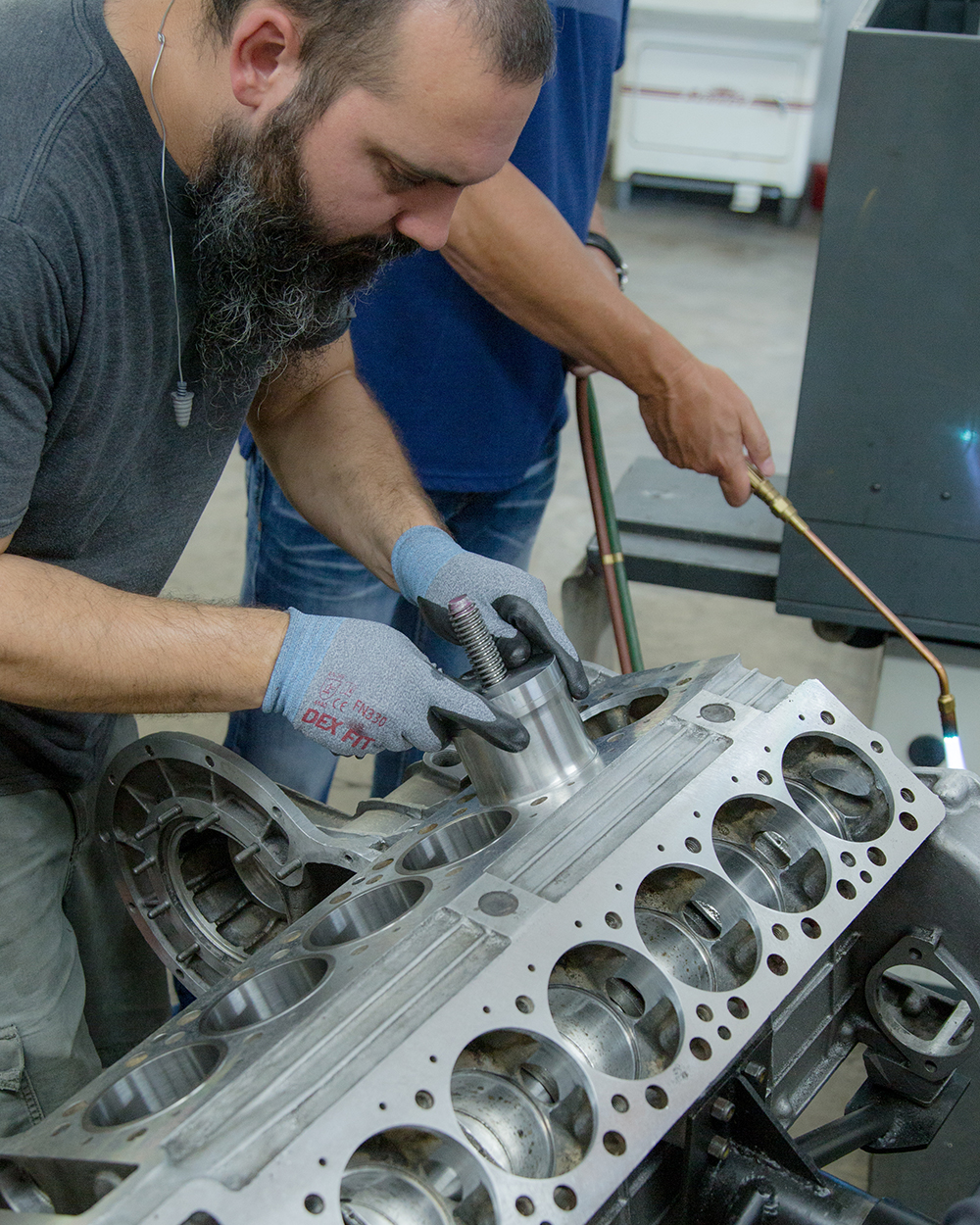
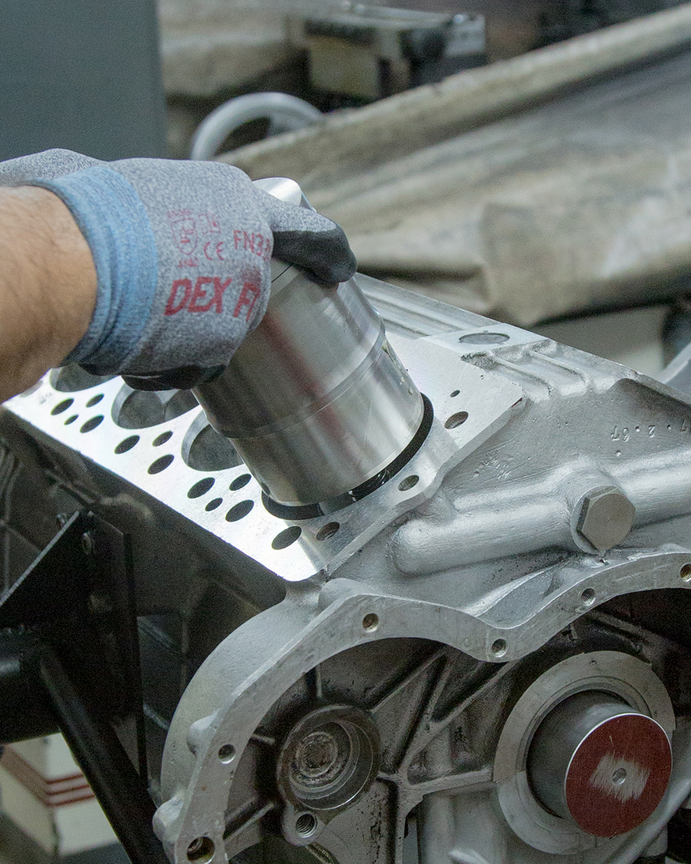
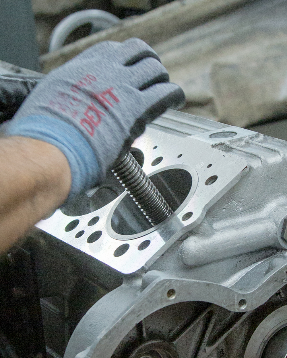
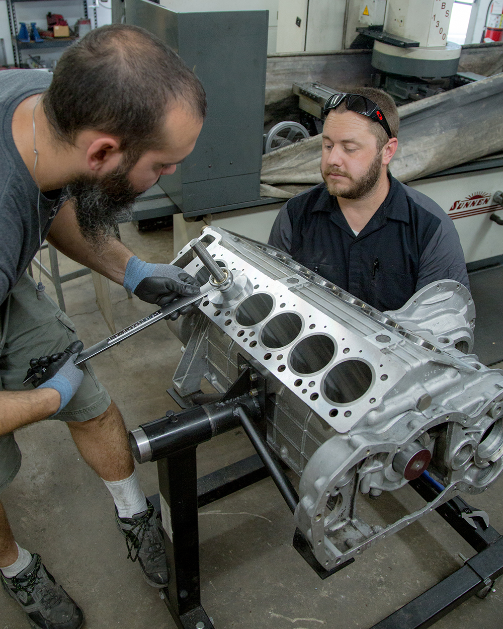
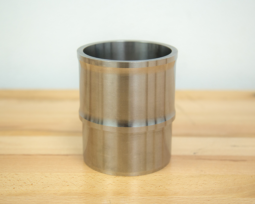
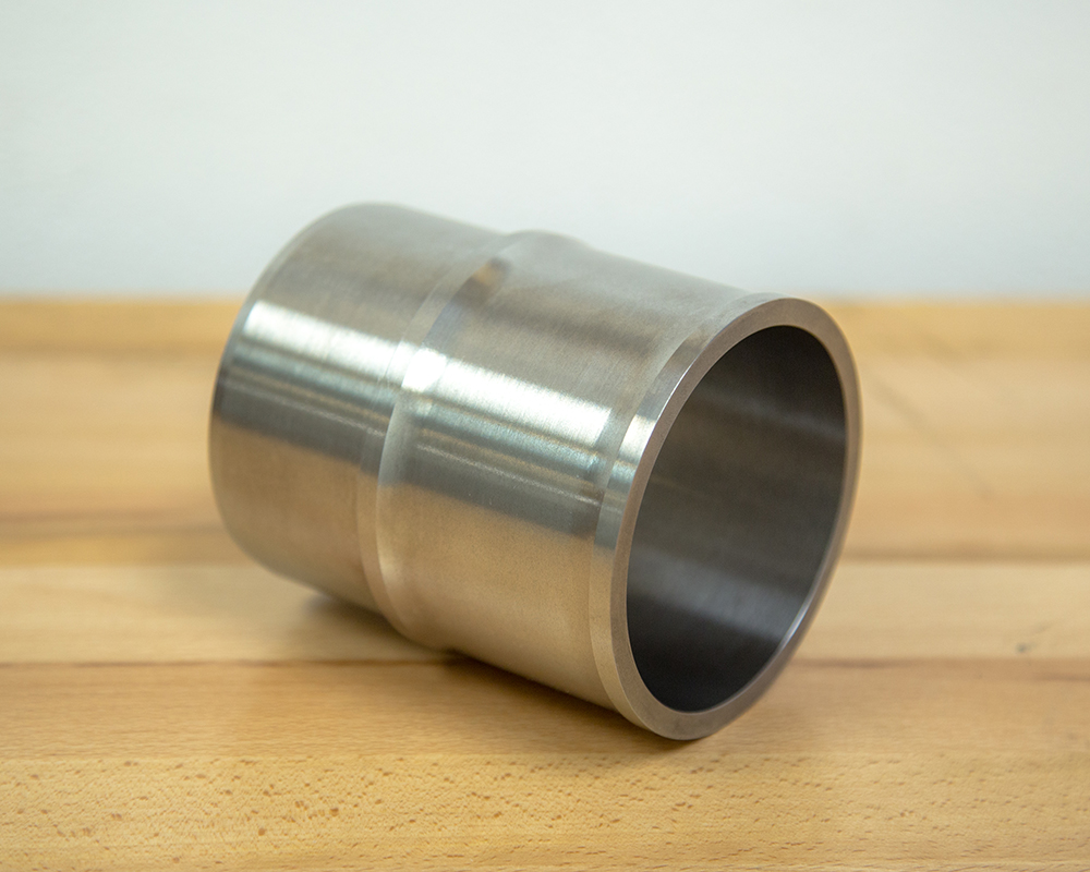
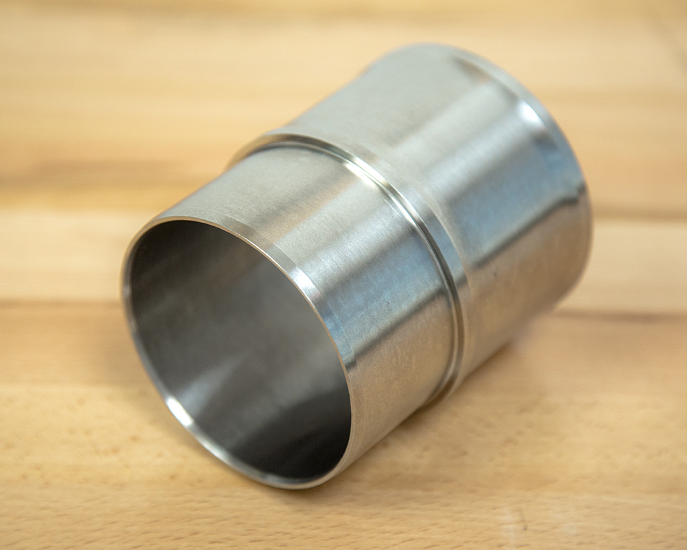
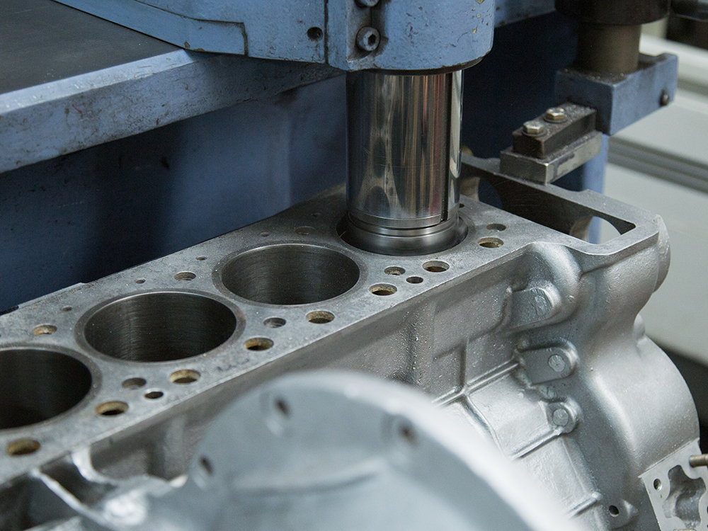
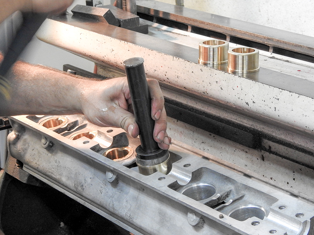
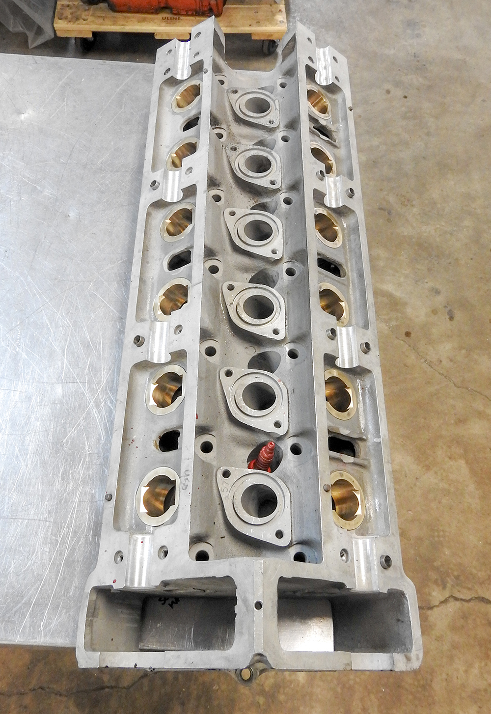
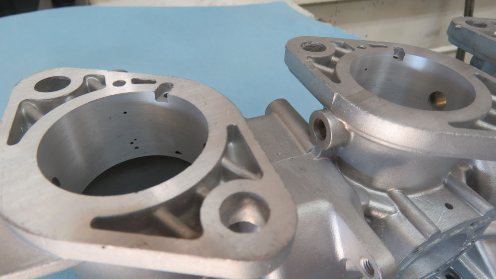
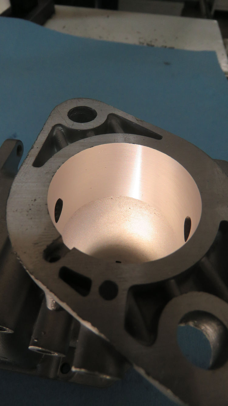
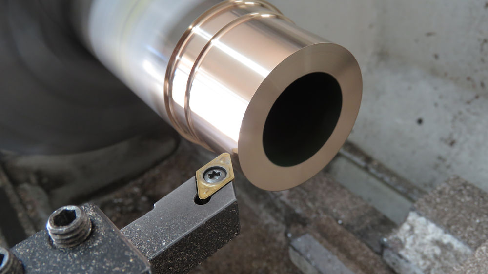
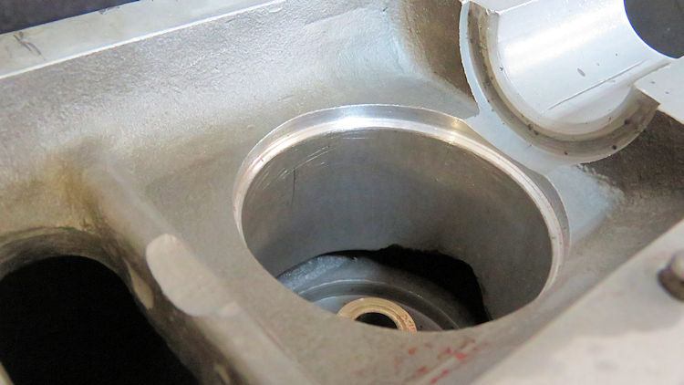
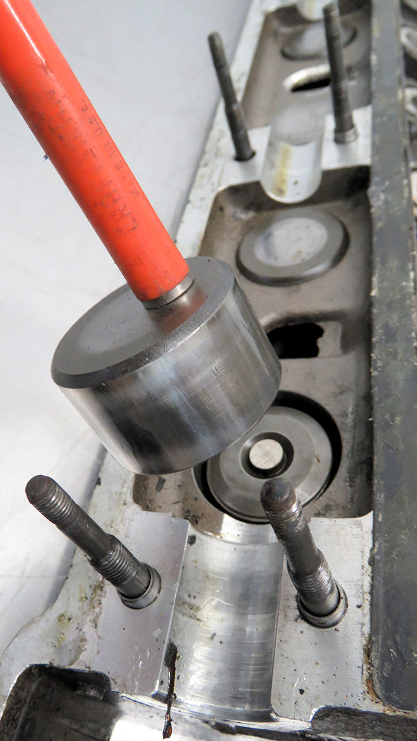
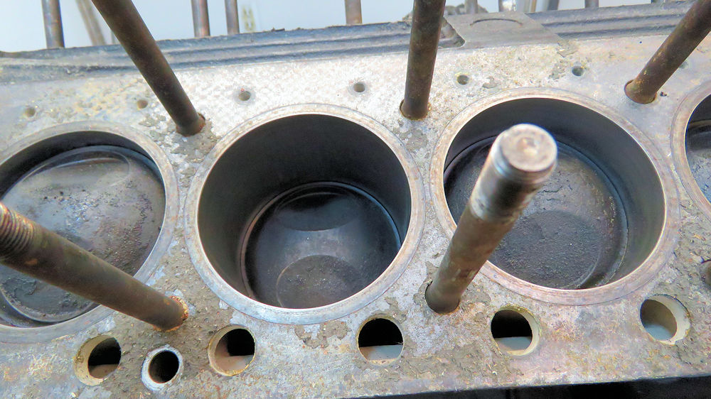
Update report - August 18, 2020
The following
sequence of photos show Corey installing the new cylinder
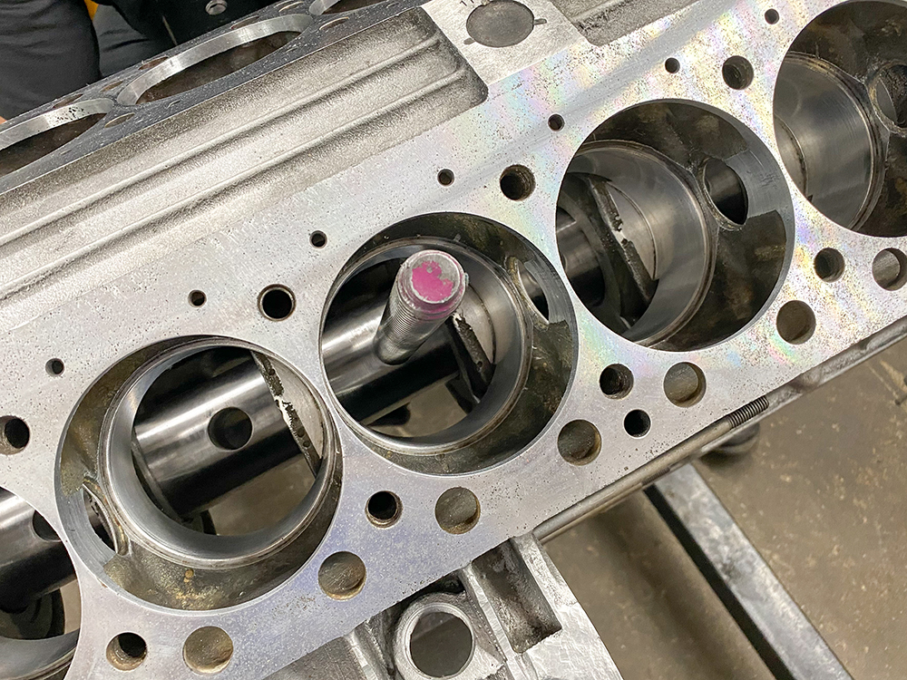
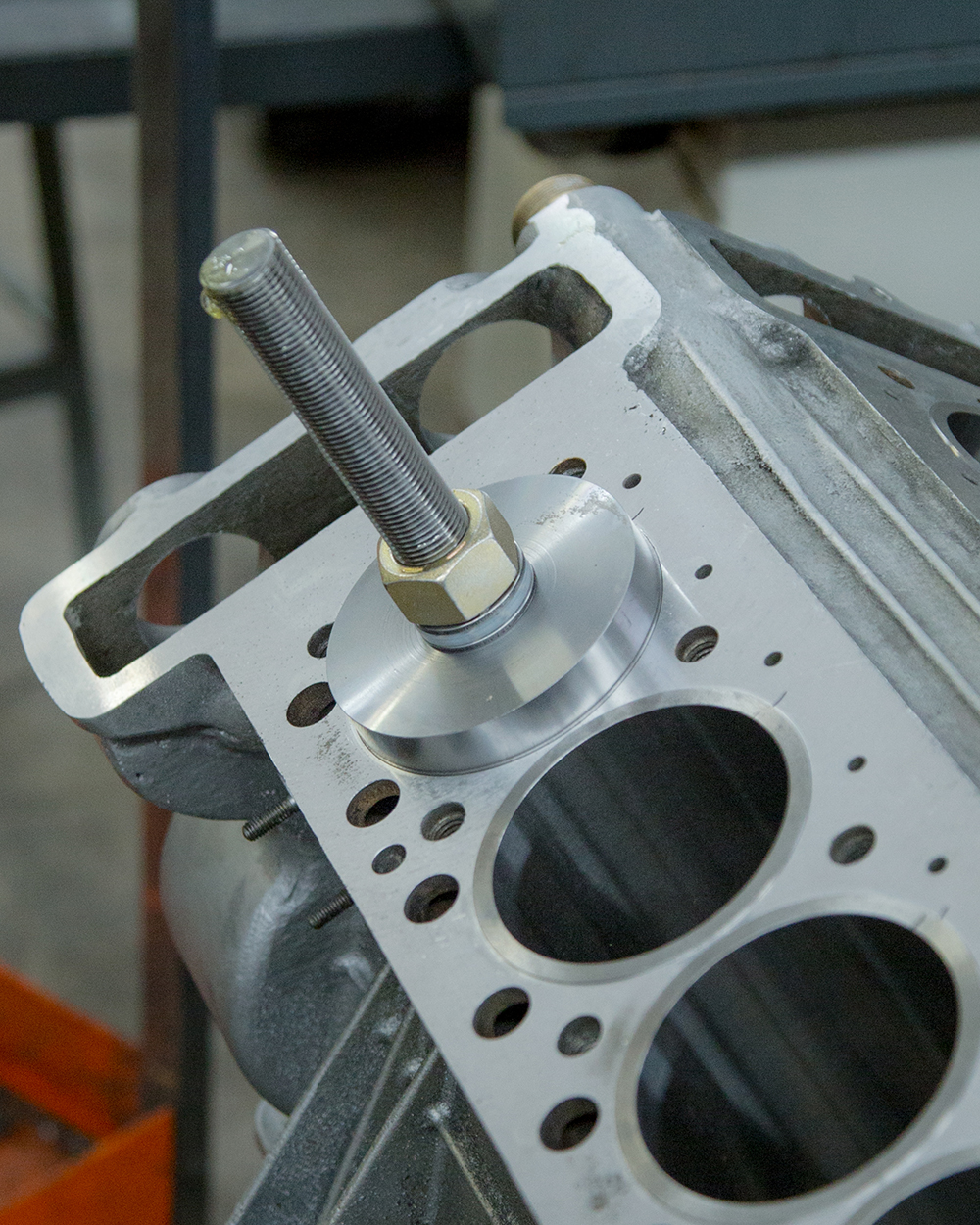
liners. During the installation process we used an arbor
that Corey designed that is installed inside the main
housings. Holes machined in the arbor allow us to insert a
large threaded rod which helps Corey position the
installation alignment tool centrally in the bore. With the
cylinder counter bores heated to about 240 deg C, they
expanded to approximately .002" larger than the new liners,
which dropped into place perfectly. Once the block cools, the liners are
installed at a press fit of at least .0035". The same arbor and threaded rod was then used
to make sure that all of the liners were pulled and
registered all the way down.
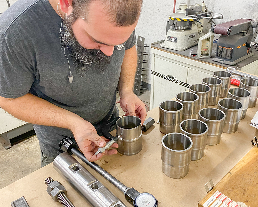
Preparing to install the new liners
Corey double checking the sizing one last time
Confirming the requisite press fit in the
cylinder
counter bores
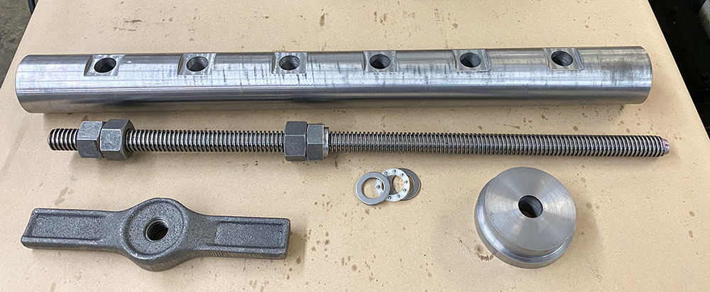
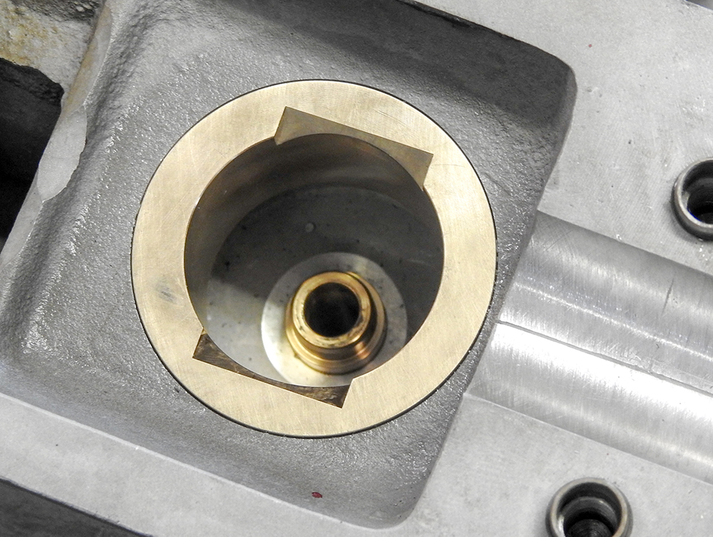
Special arbor and installation tool for the
Miura block
Heating the counter bores to around 240 deg C
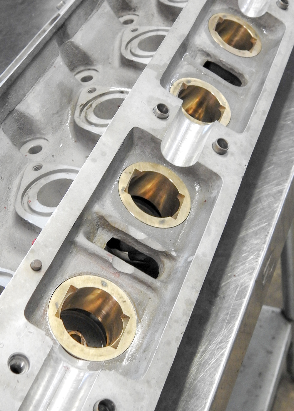
Installing the first of the liners
The liners will now be surfaced to ensure they
are
the requisite height above the deck surface
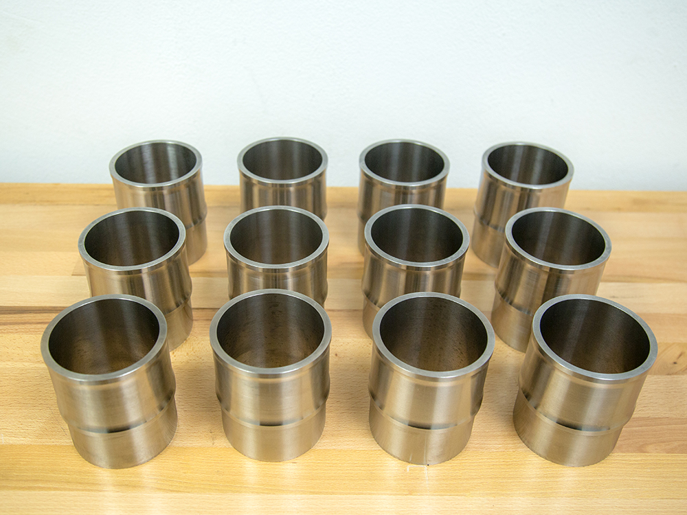
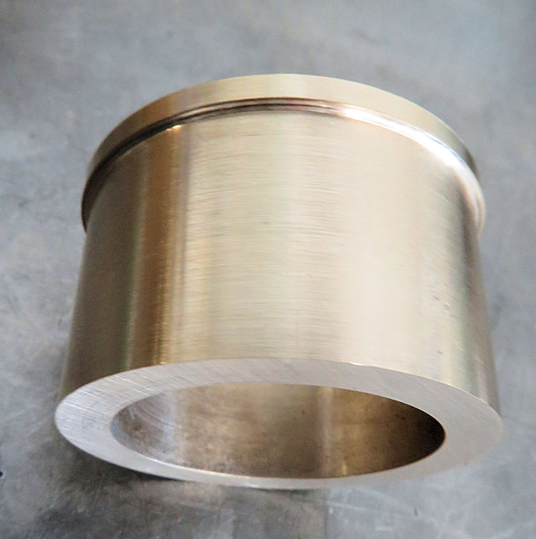
Update report - August 5,
2020
A new set
of bespoke ductile liners for the cylinder block.
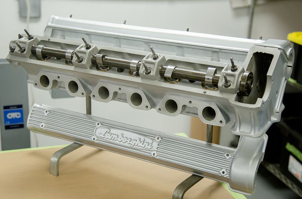
Update report - July 23,
2020
Corey has
now completely rebuilt and reassembled both cylinder
heads.
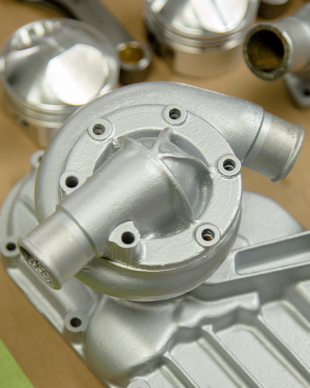
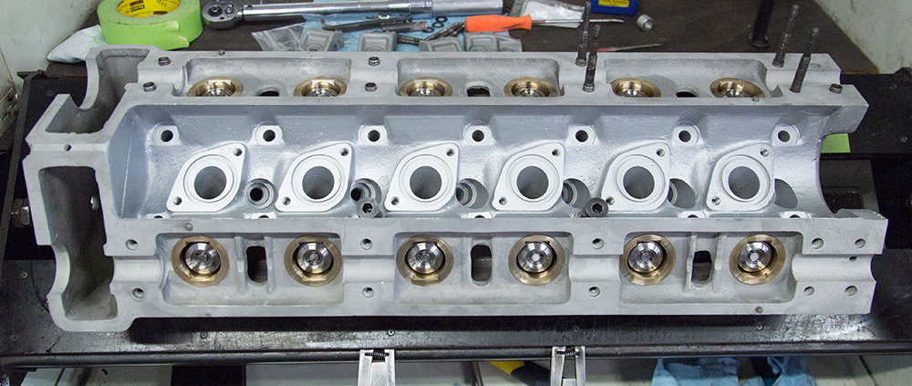
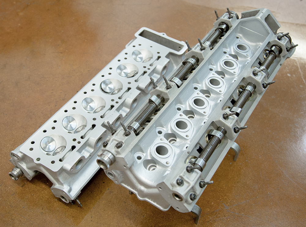
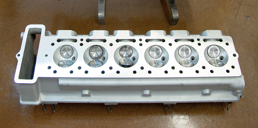
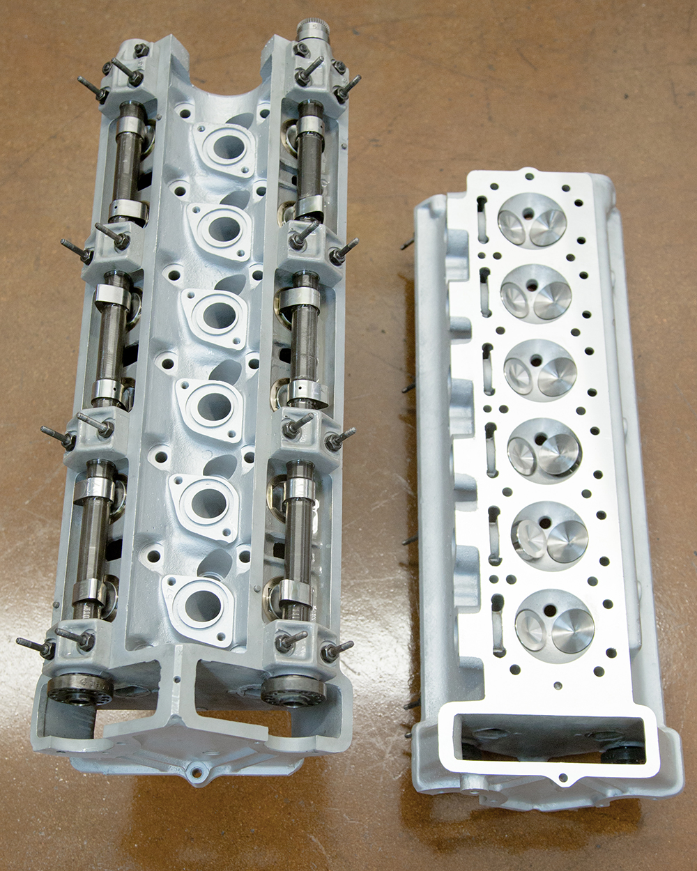
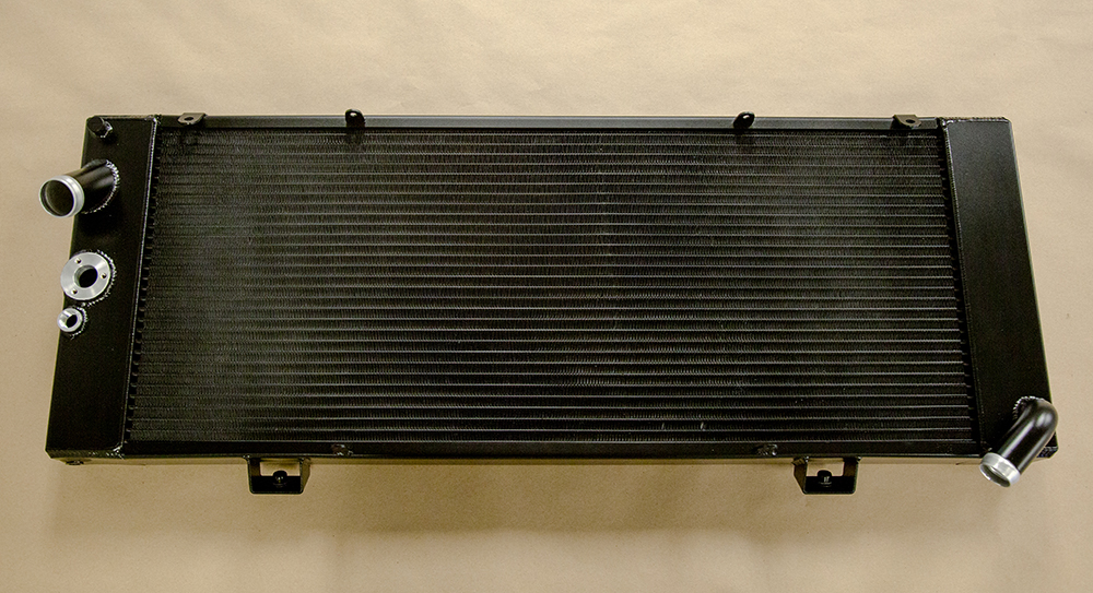
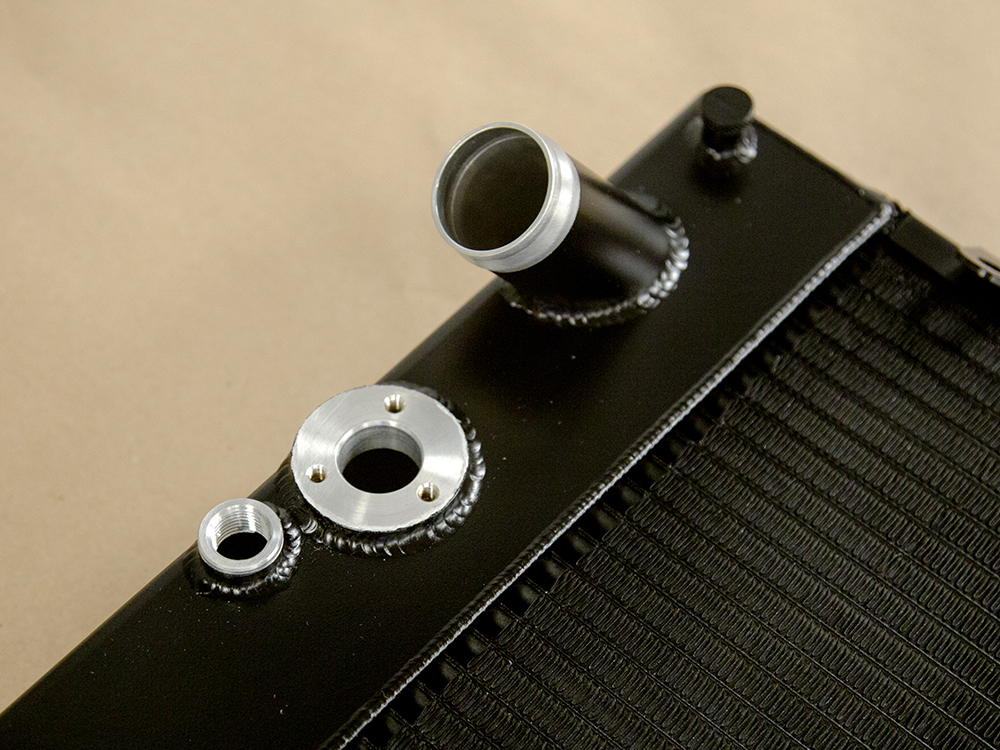
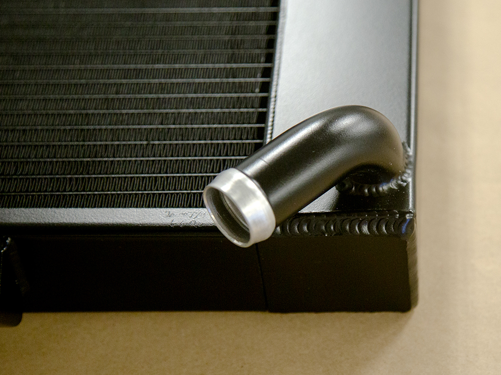
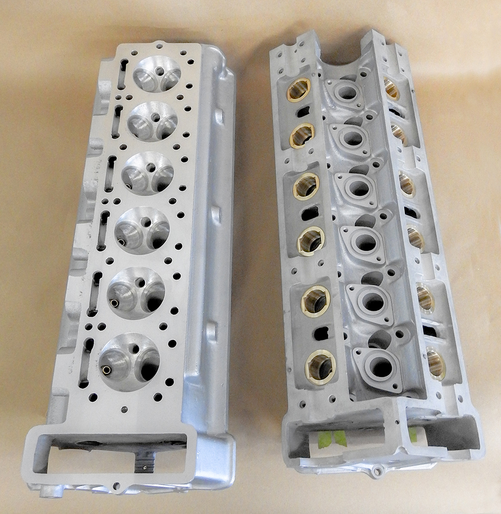
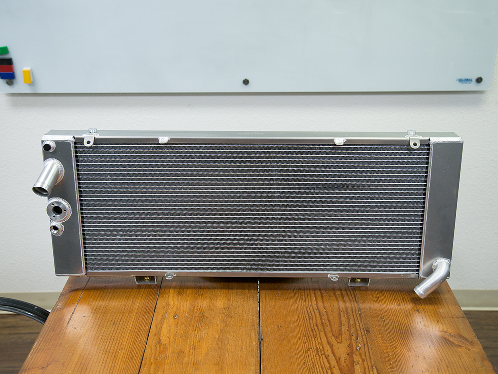
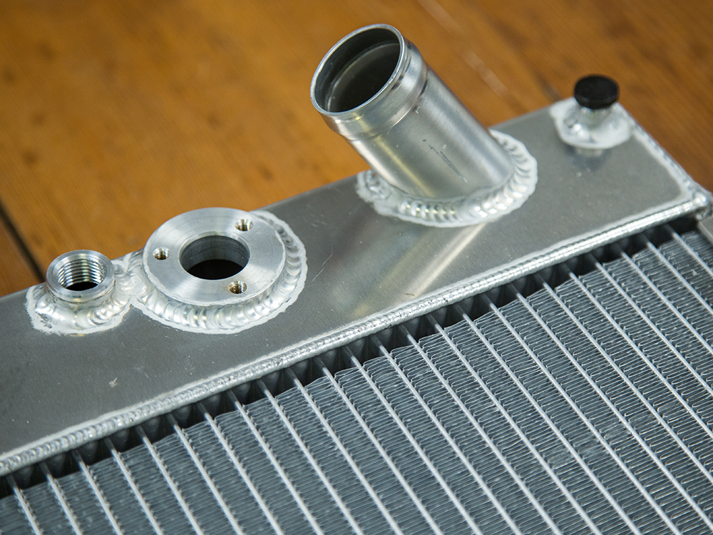
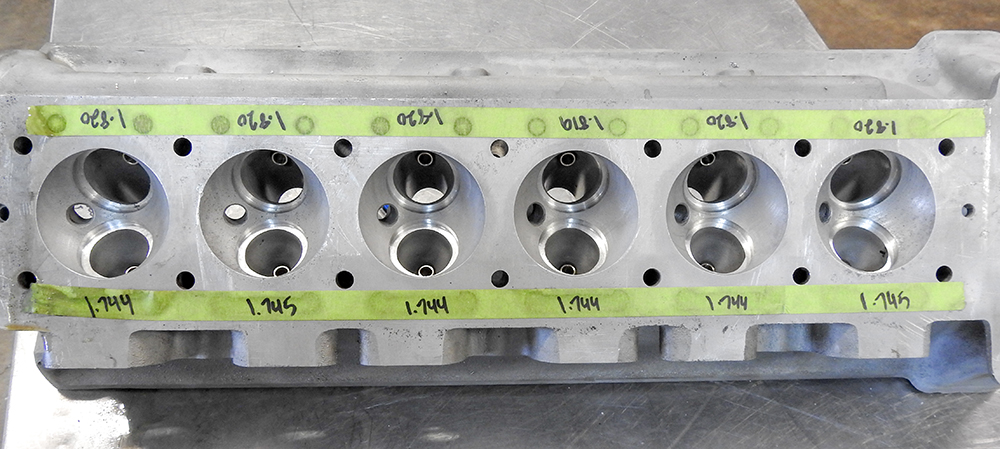
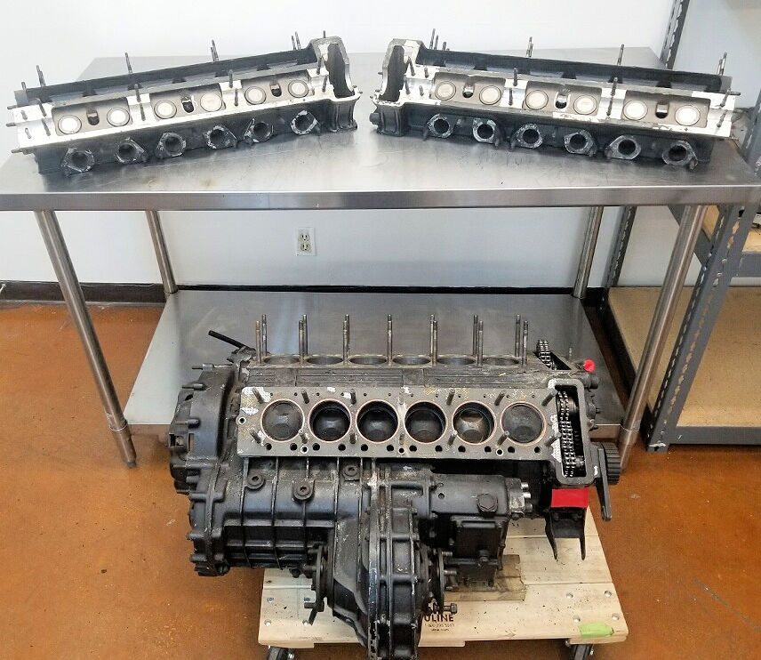
Update report - July 13, 2020
We have now
completed all of the machine work to the cylinder heads,
which are both ready to be assembled. The first photos in
the sequence show the new radiator painted satin black.
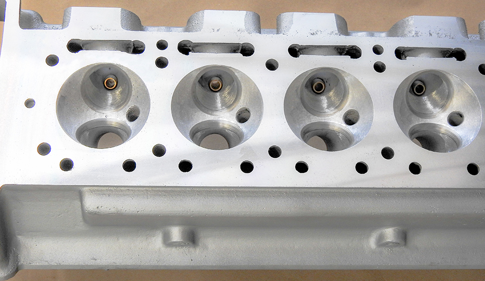
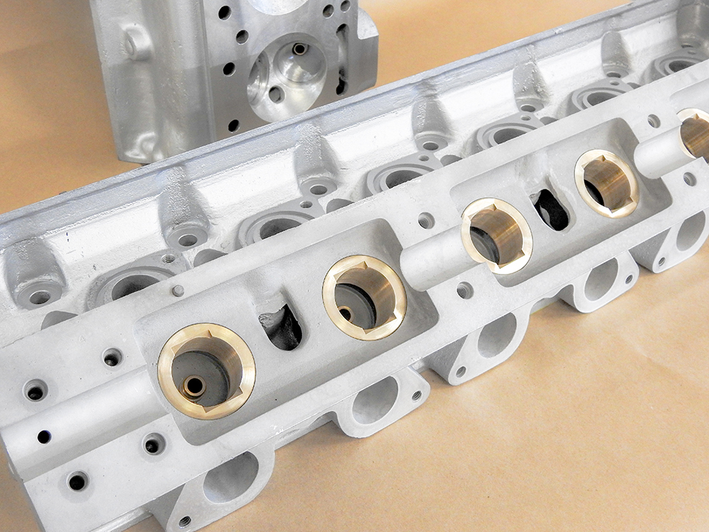
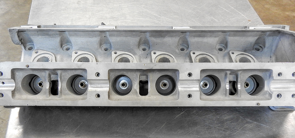
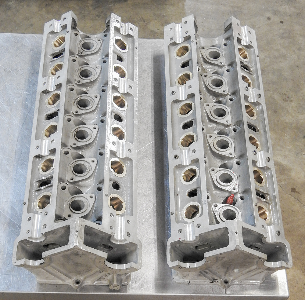
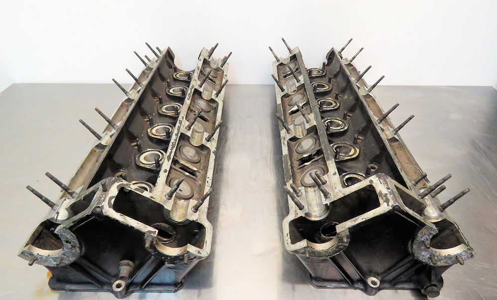
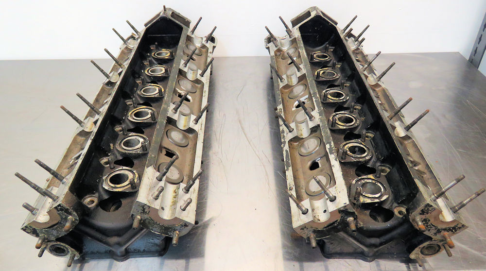
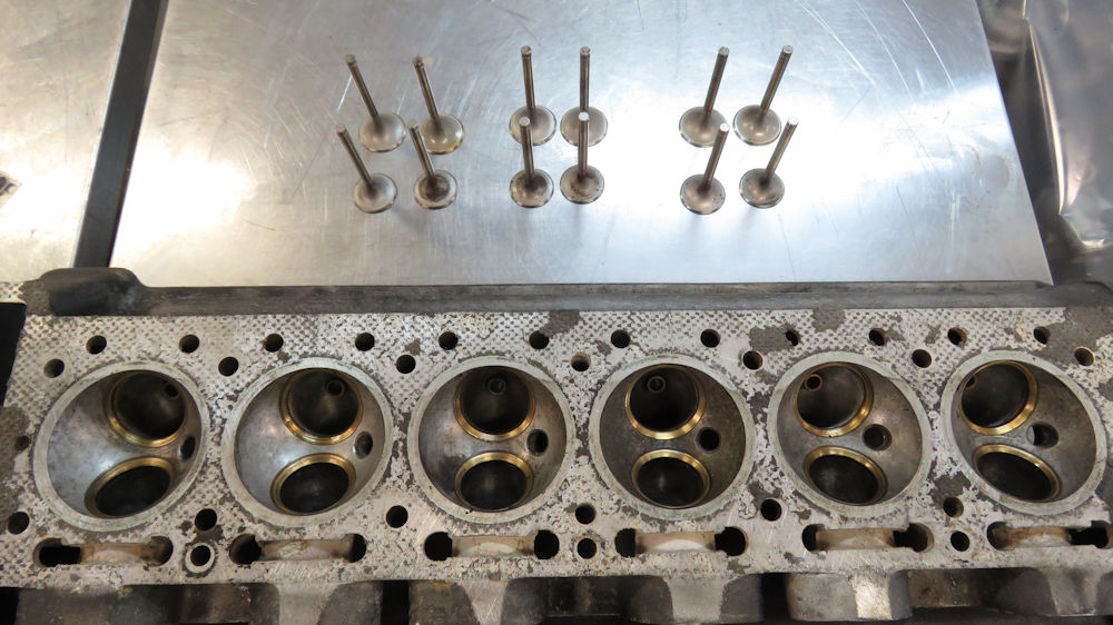
A reminder of how the cylinder heads looked at
the start of this project
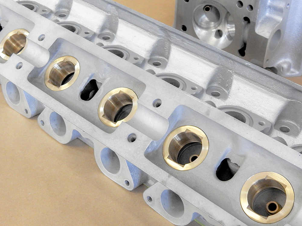
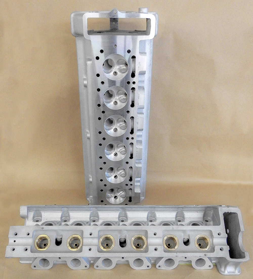
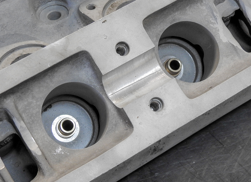
Both heads have now been machined, repaired
and
restored
Heads will be assembled in the next couple of
days
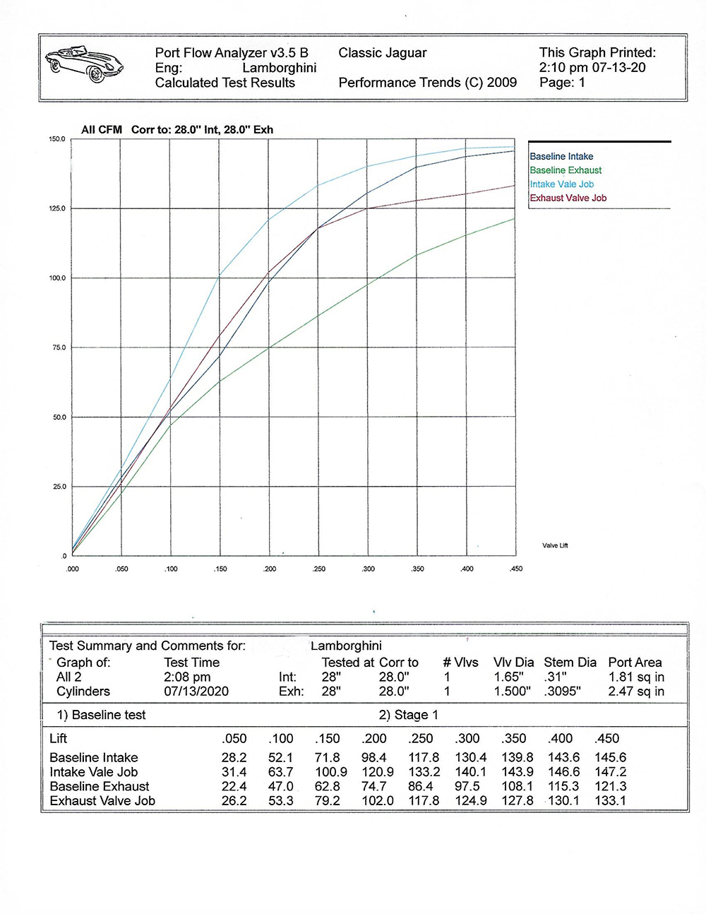
Some nice gains on the flow bench from Corey's
valve job
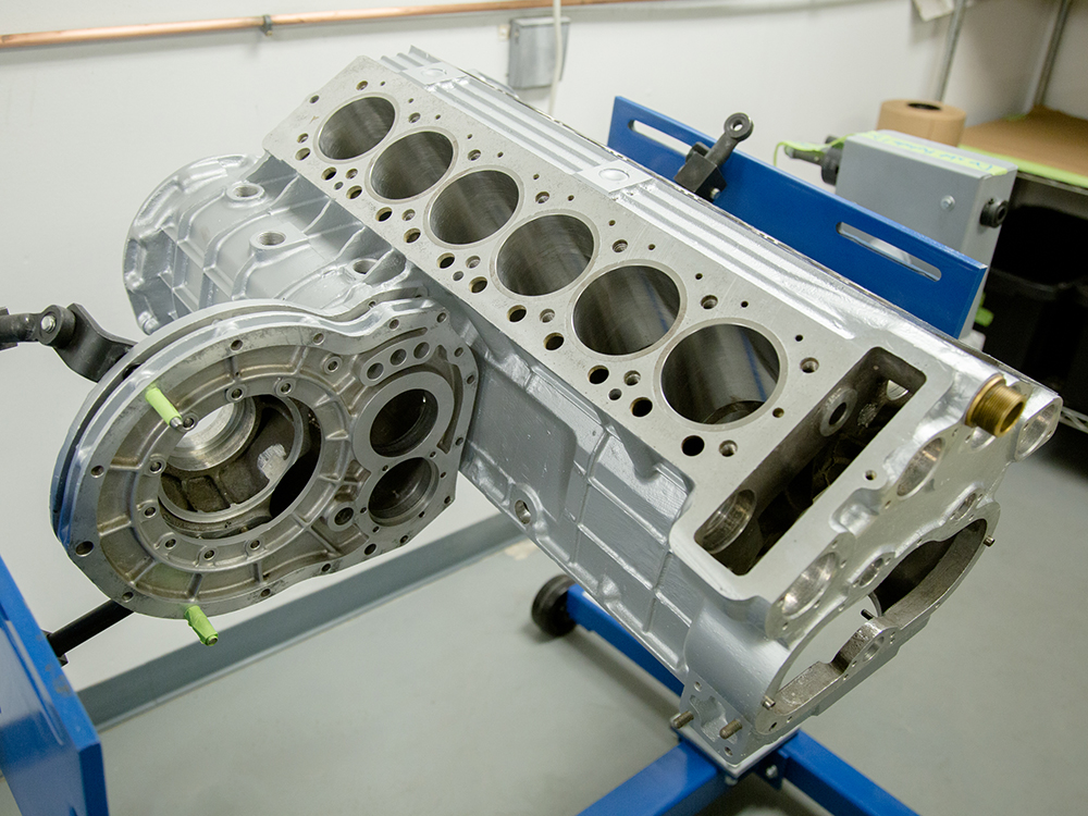
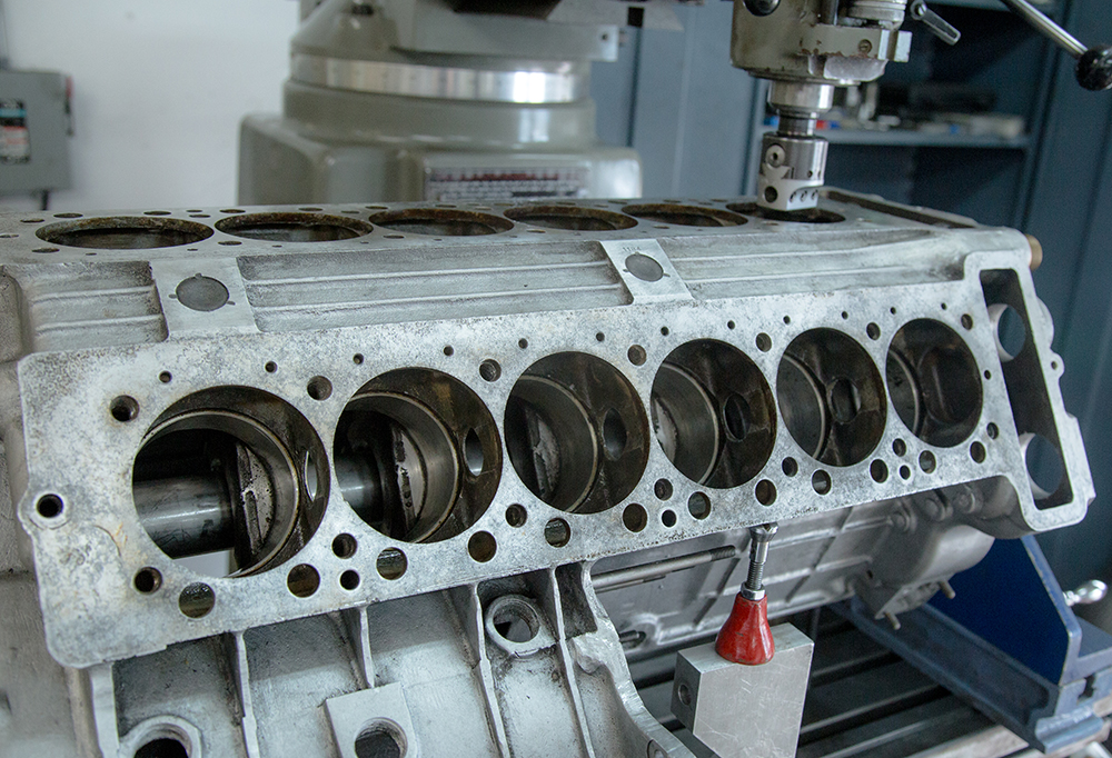
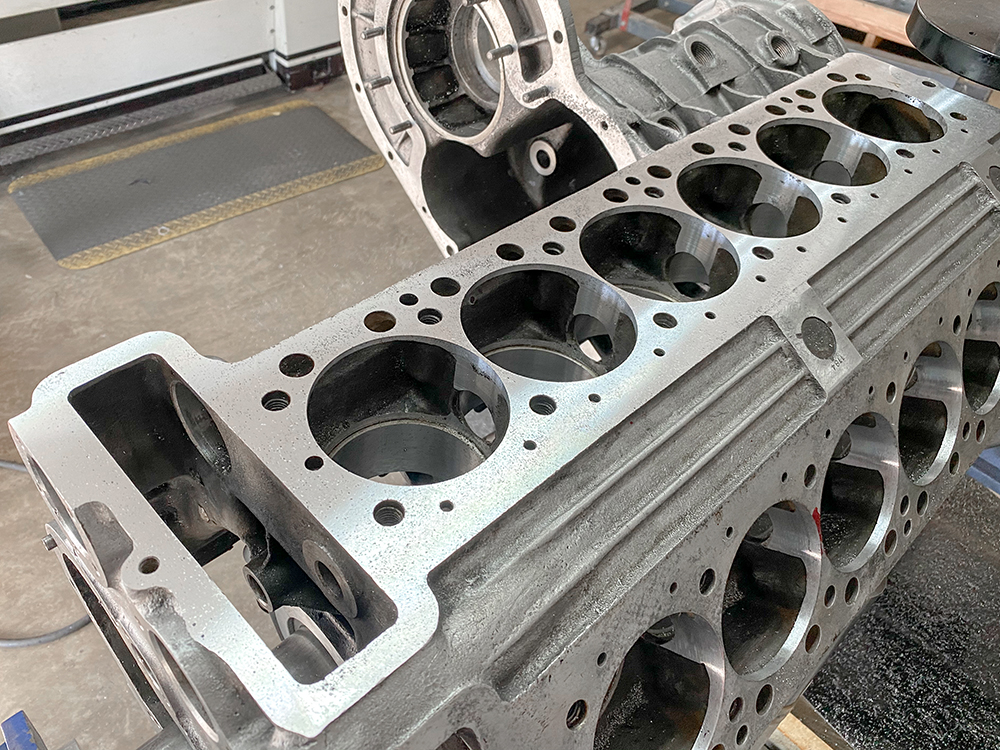
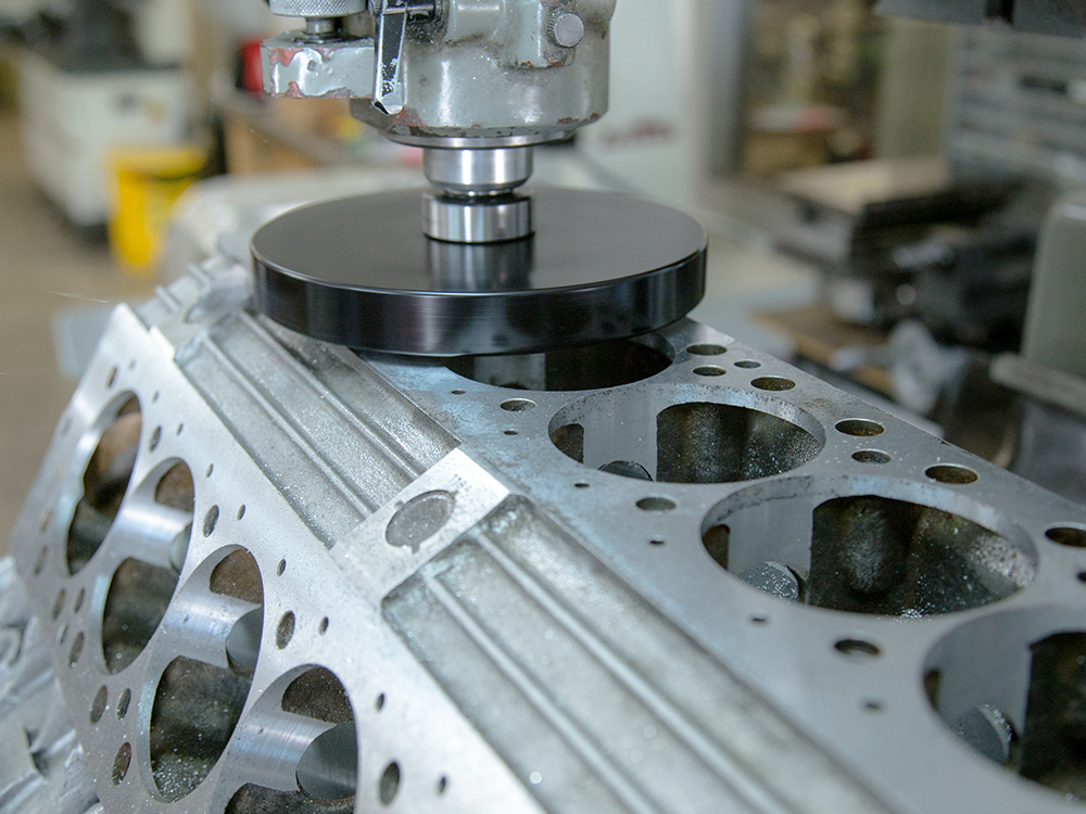
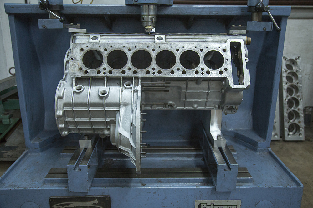
Update report - July 10, 2020
Video clip
showing Corey surfacing the block
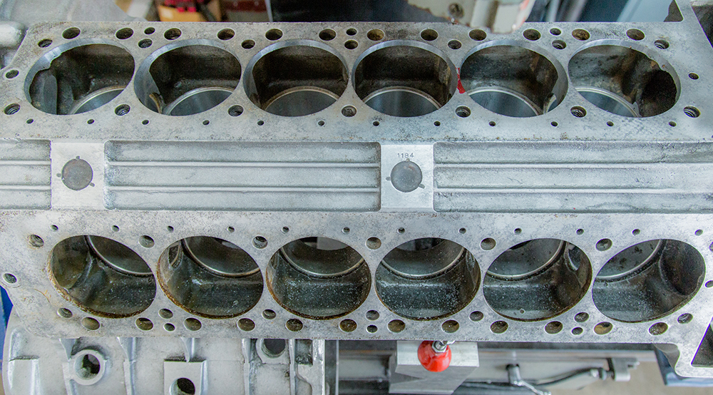
We have now removed all the old liners and surfaced the
decks. Funnily enough the only flaw that remains in the deck
surfaces is scarring from an old weld that was undoubtedly
done at the Sant'Agata factory in 1967!
Machine out the original liners
A rarely seen view of the water jackets inside
a
Miura cylinder block
Preparing to surface the block deck surfaces
The majority of the pitting has now been
removed
and the deck surfaces are smooth and true
Checking straightness with a straight edge
Remains of a factory weld!
Ready for the new liners
Update report - June 12, 2020
Dan Mooney
explaining issues with the Miura block and liner replacement
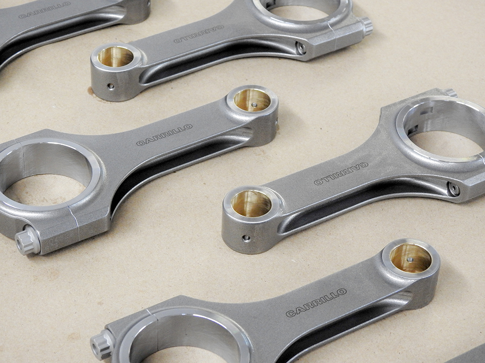
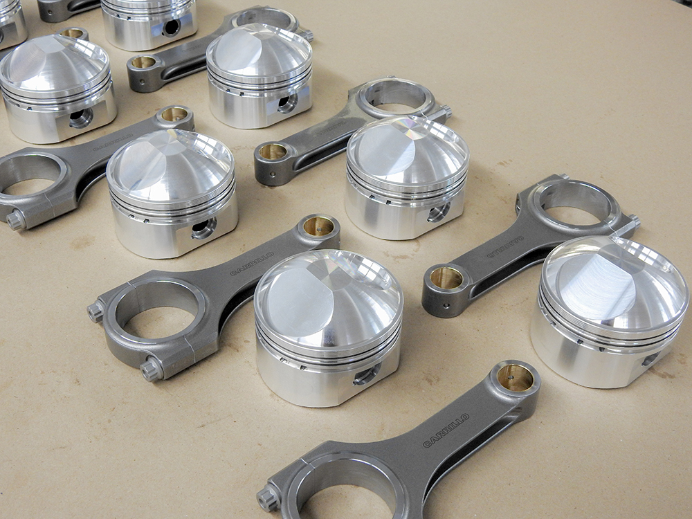
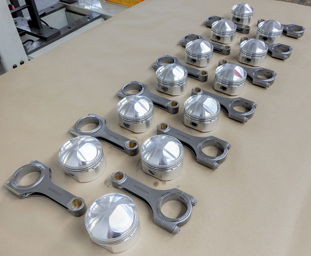
Update report - May 20,
2020
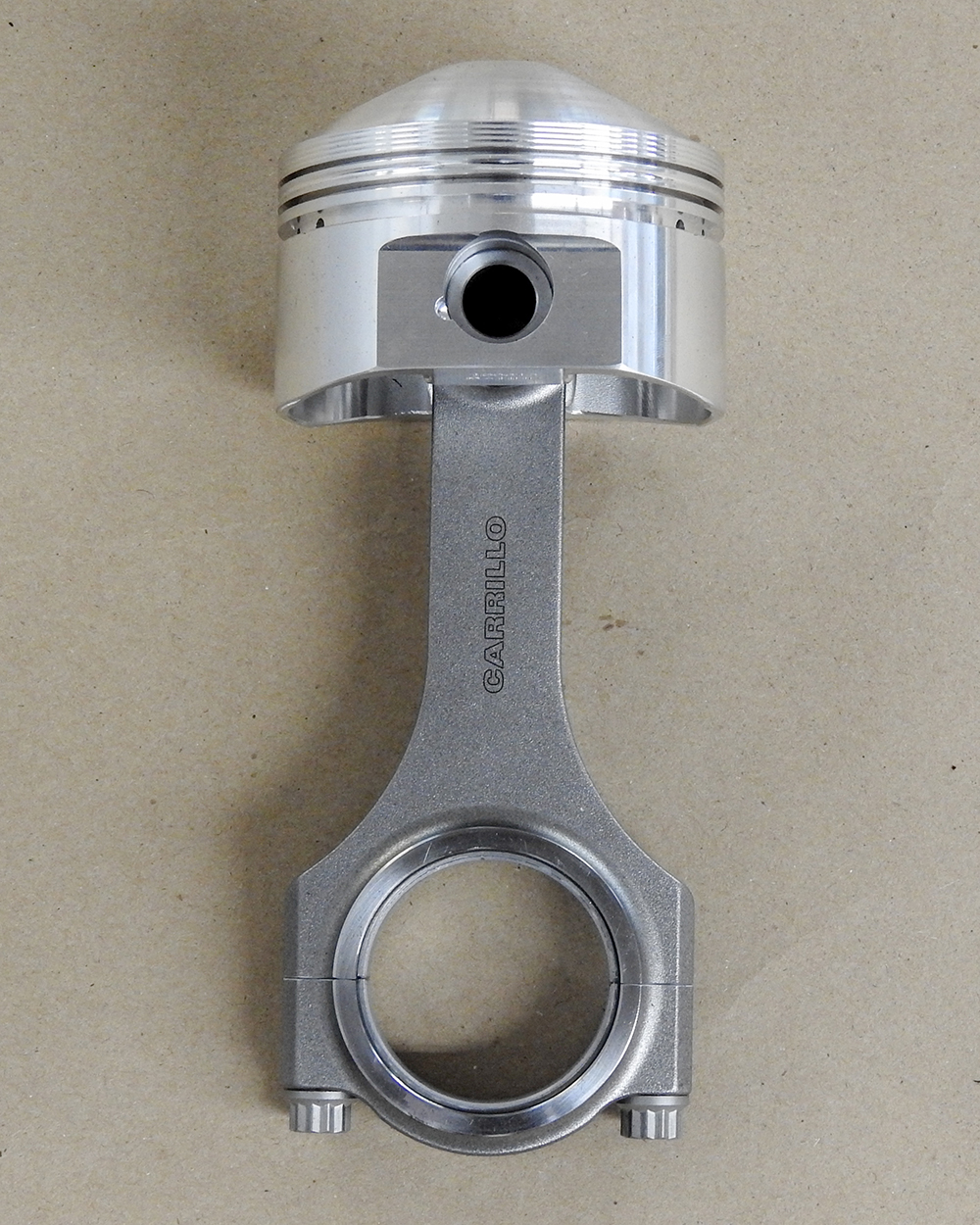
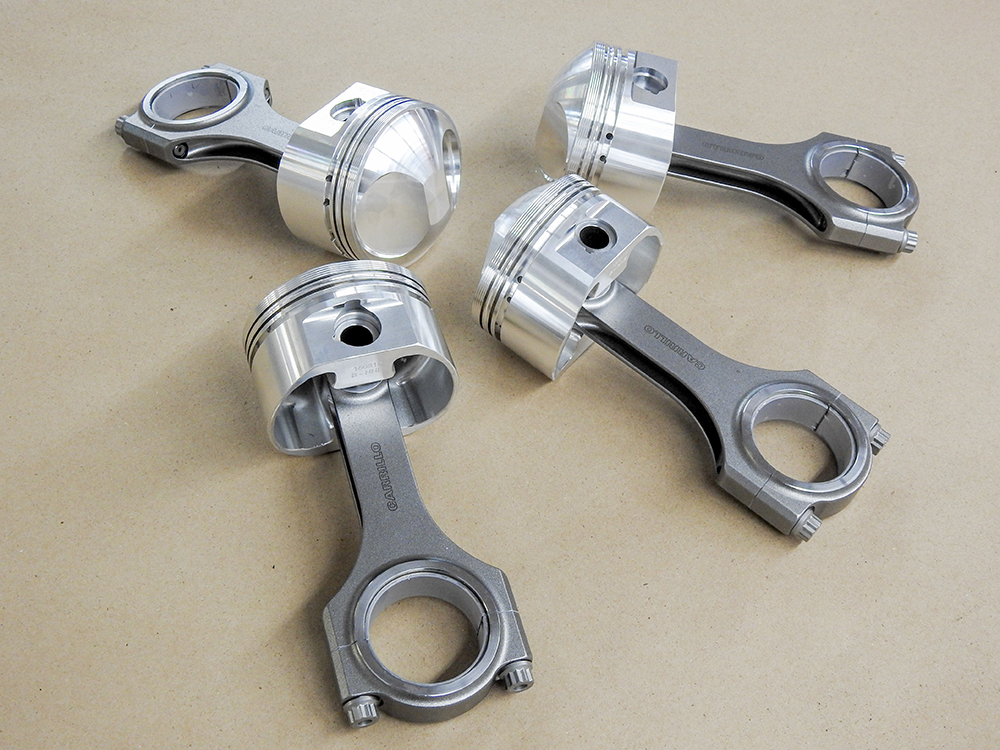
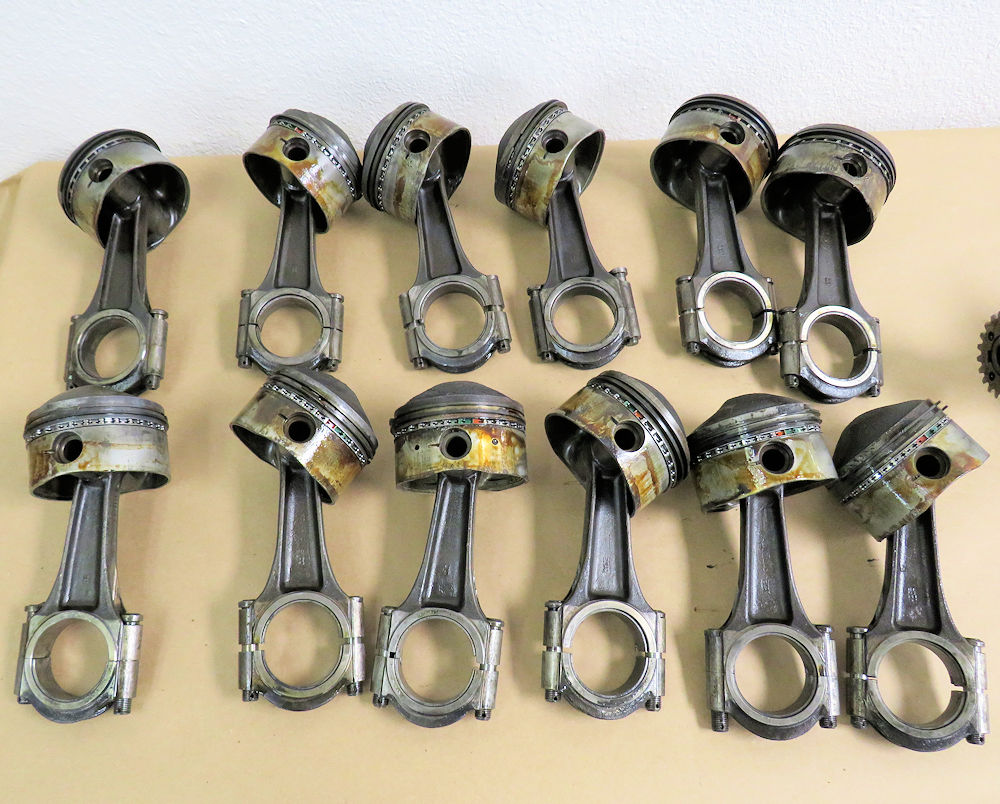
Hanging new Carrillo rods
on the pistons.
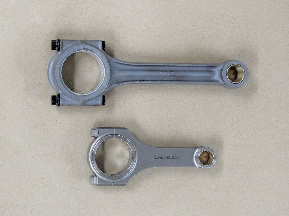
Forged Carrillo rod saves over 600g from the
rotating assembly
Comparison with Jaguar rod shows just how
diminutive the Miura rod is!
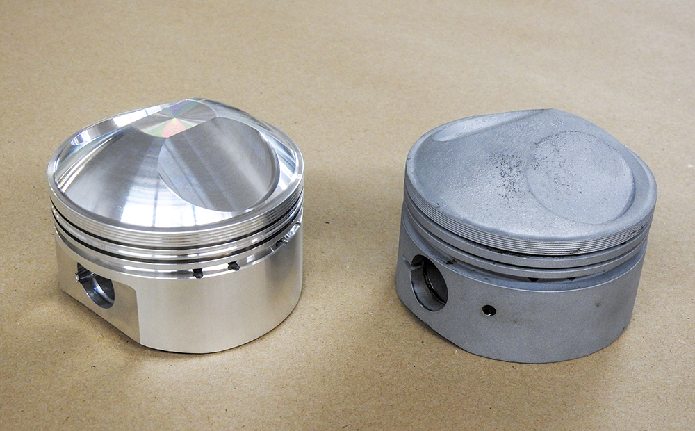
Update
report - May 15, 2020
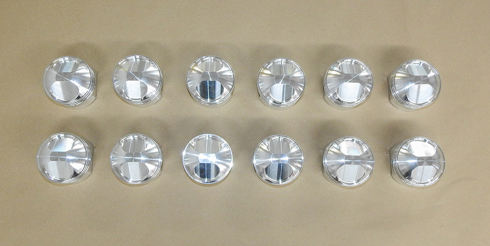
Honing tappet guides and
new forged piston set.
Honing the tappet guides to size
New forged piston side by side with the
original
cast version
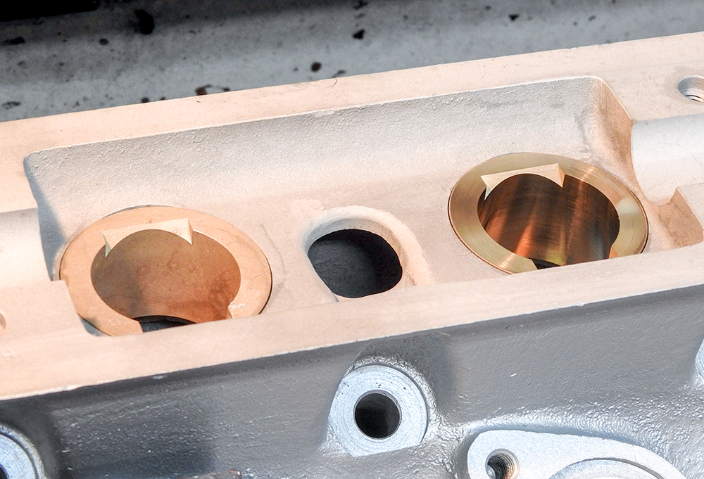
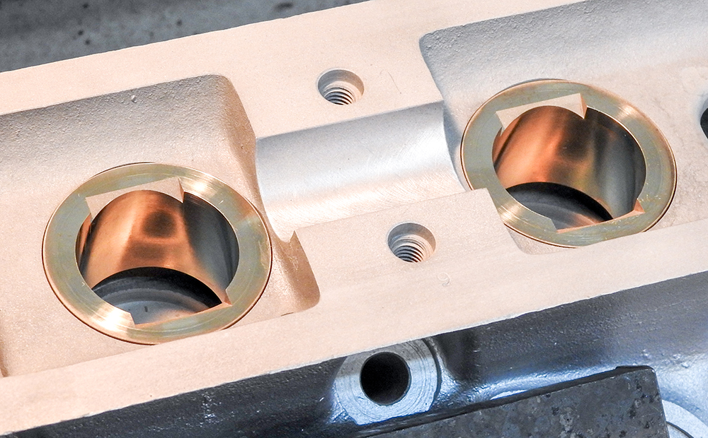
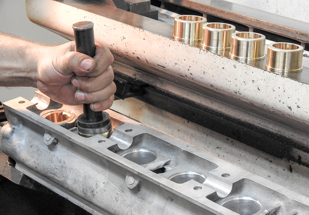
Update report - May 13, 2020
The
following sequence of photographs show Corey machining the
cylinder heads.
Valve seat pockets machined to size
New custom valve seats pressed into place
Valve guides installed and honed
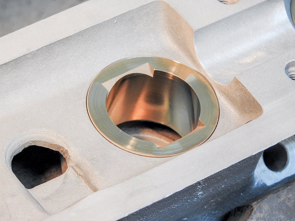
Machining bores for bronze tappet guides
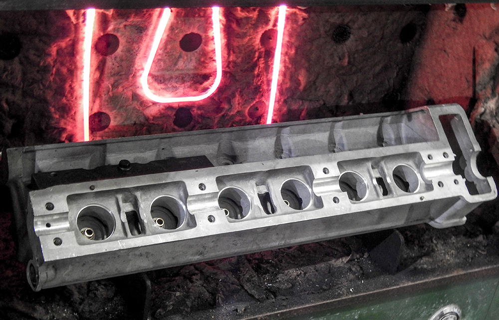
Heating head prior to pressing in tappet
guides
Tappet guides now installed in first head
Installing guides in second head
To be continued!
Update
report - May 5, 2020
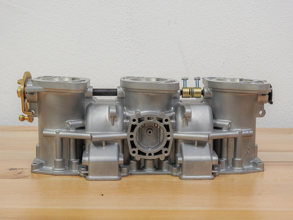
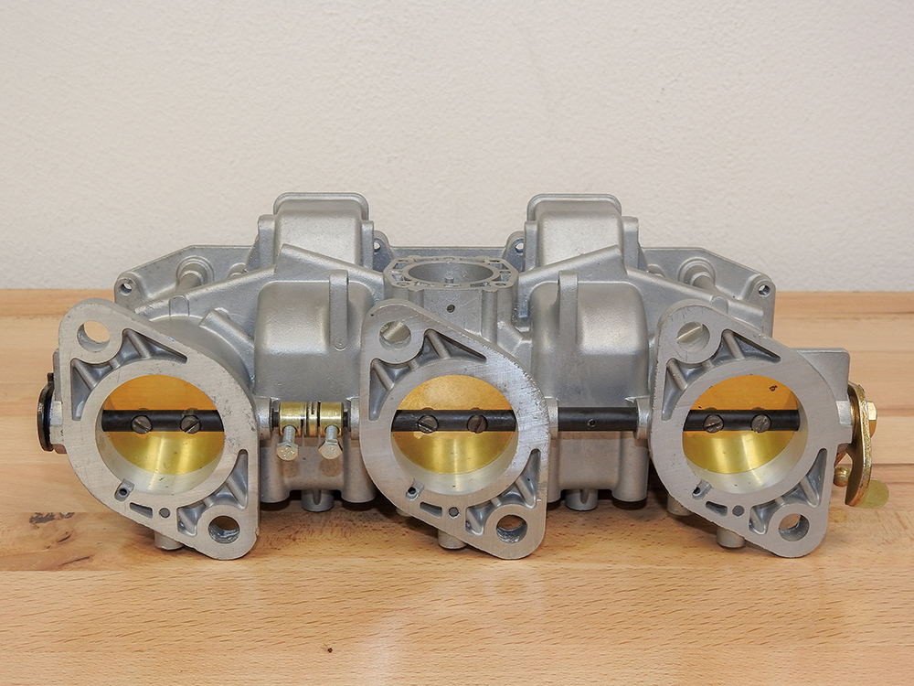
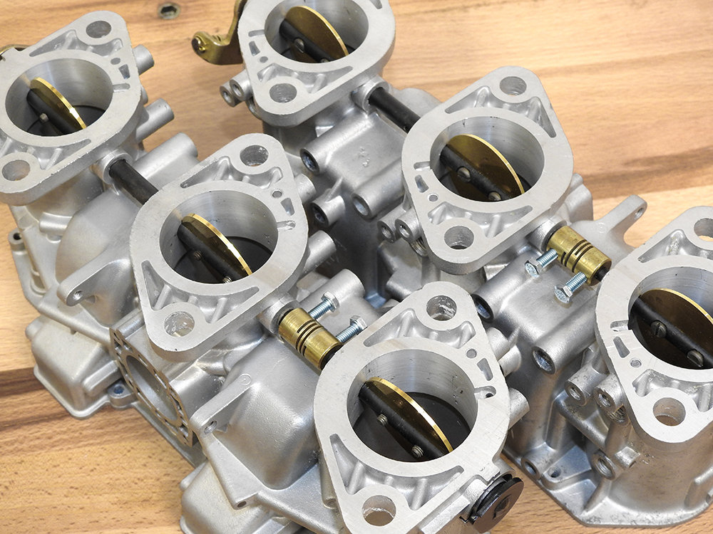
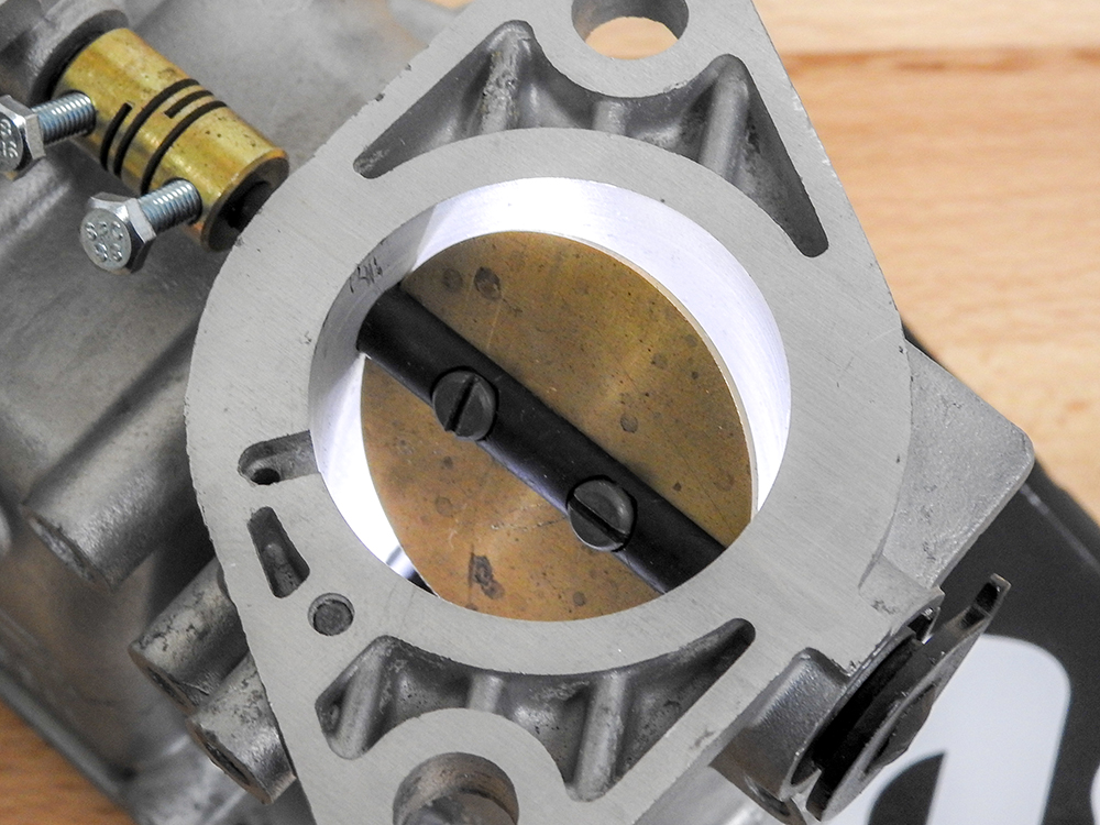
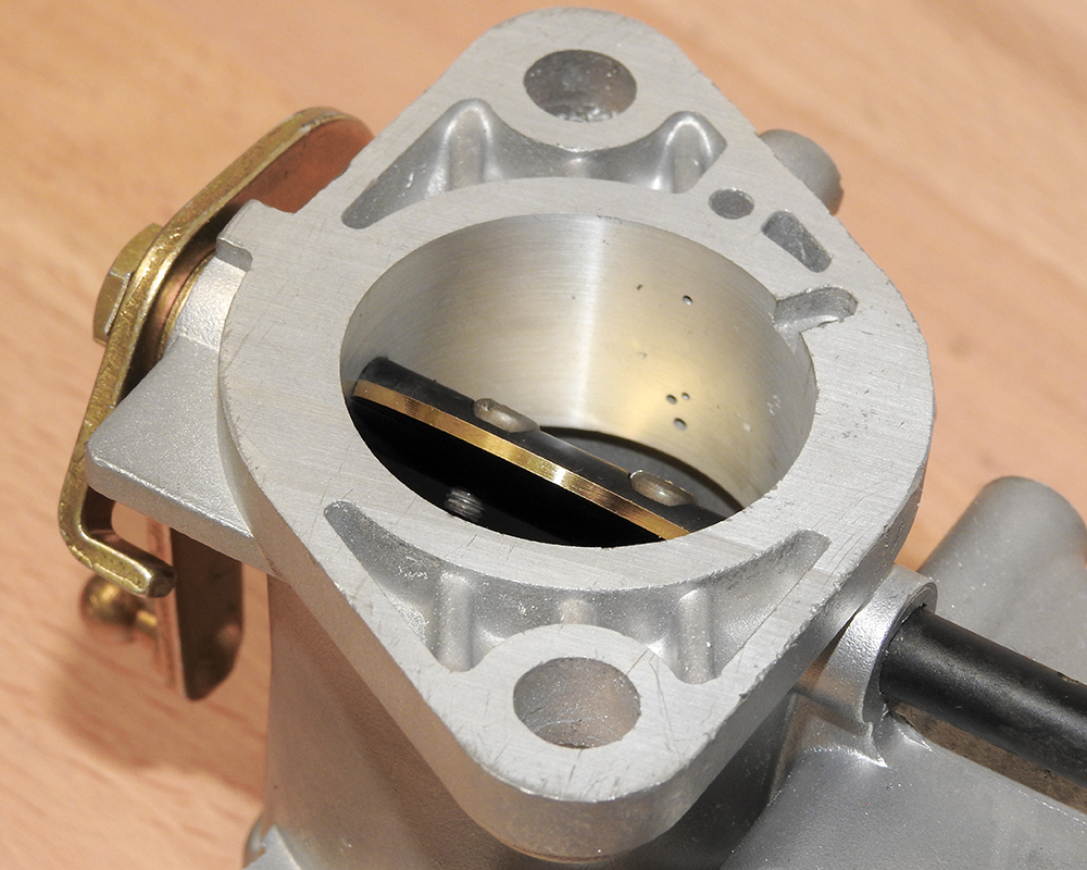
Update report - April 21, 2020
Assembling the
carbs with the custom oversized butterflies.
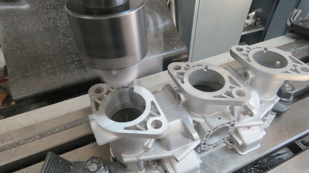
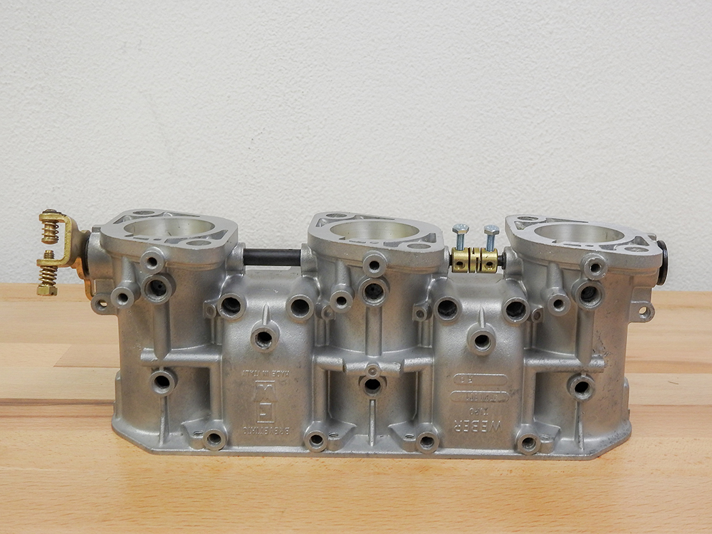
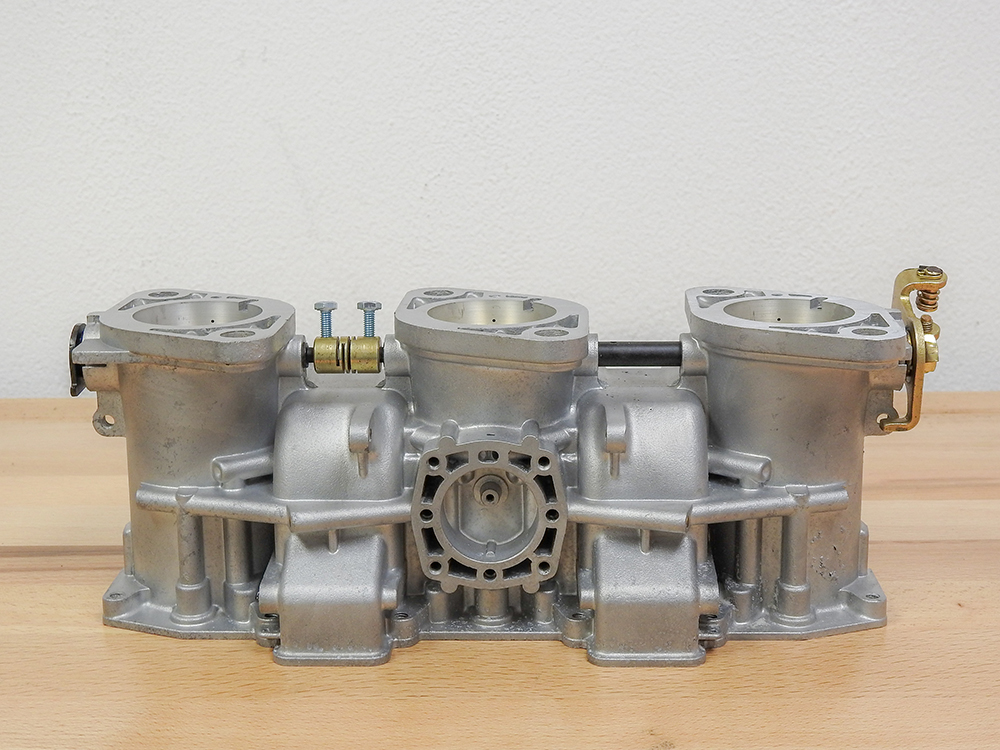
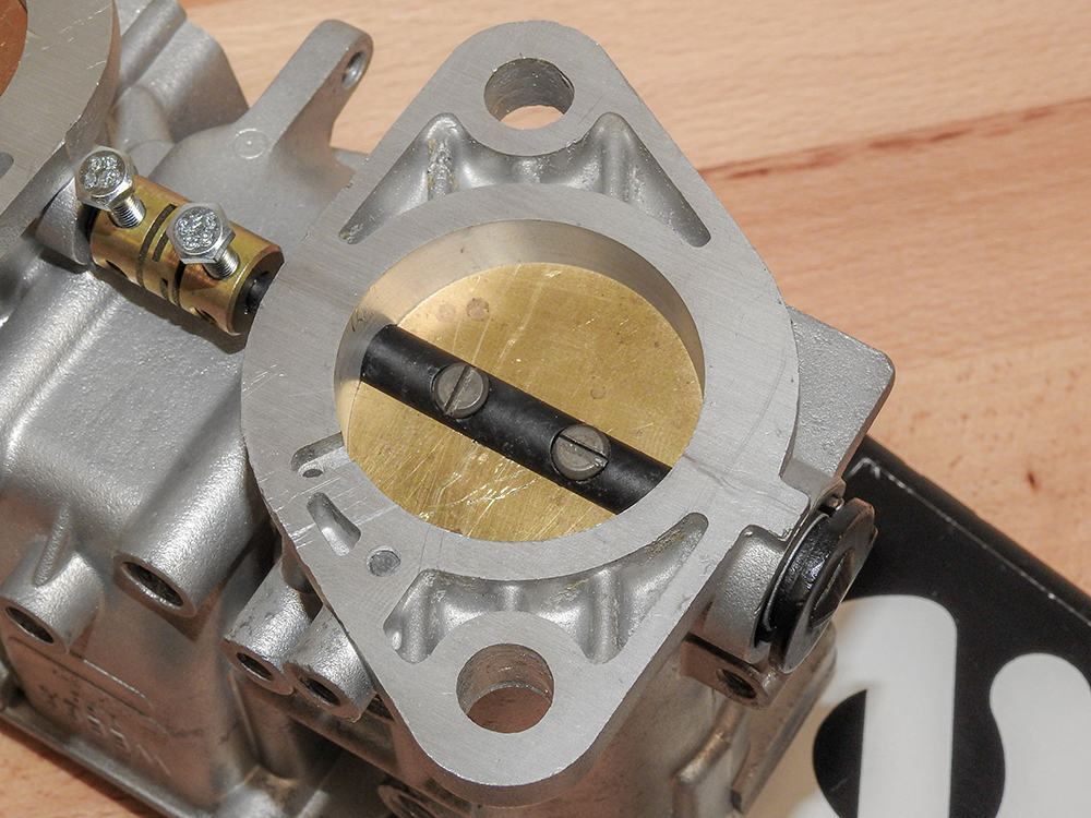
Update
report - March 13, 2020
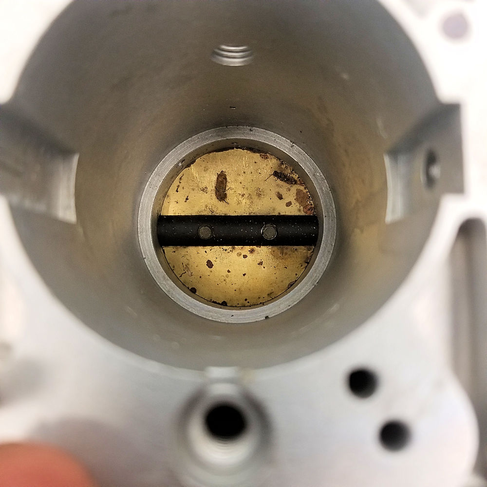
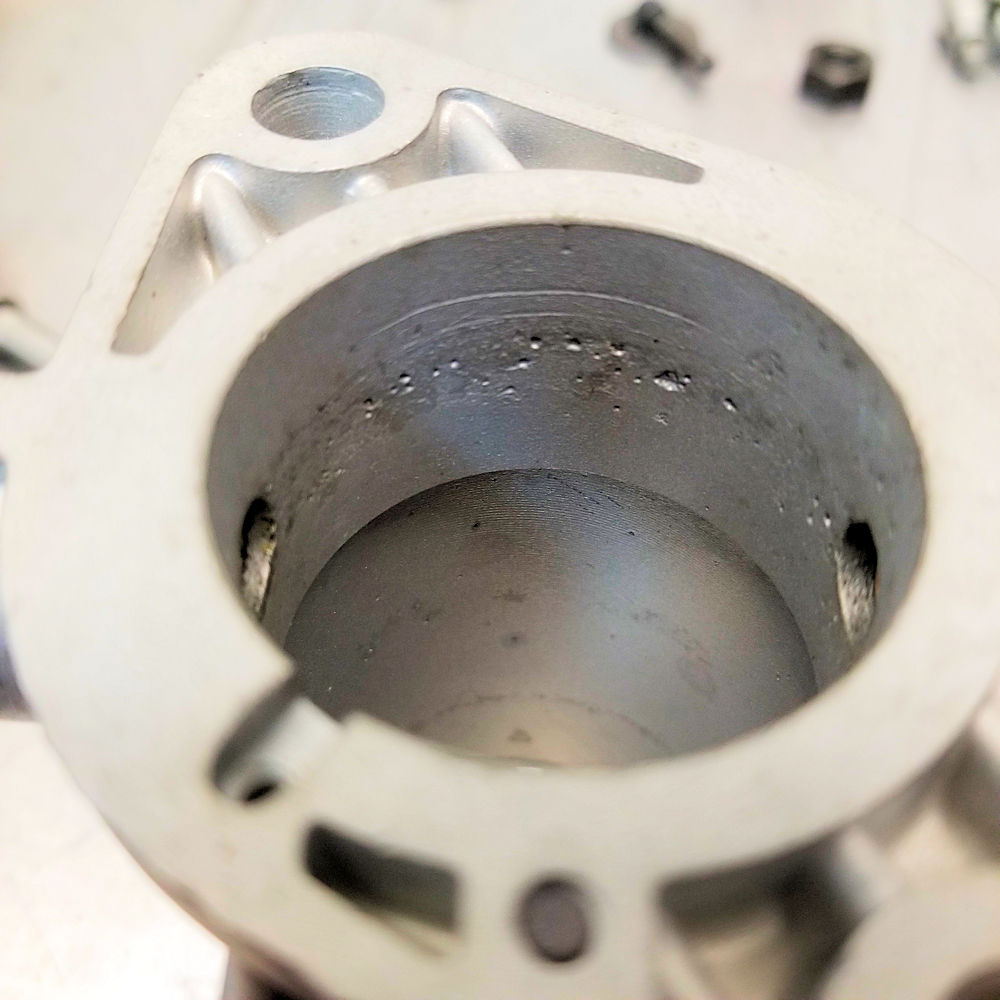
The first five photos in the
sequence below show how Corey in the Team CJ machine shop
dealt with the serious corrosion and pitting we found
inside the Weber carburetors. Rather than go with an
alternative set of carbs, we decided to machine the throats of the damaged
carbs to eliminate the pitting, then fabricate and use
slightly oversized (41mm) butterflies throughout.
The original carbs were badly pitted and could
not be used as they were
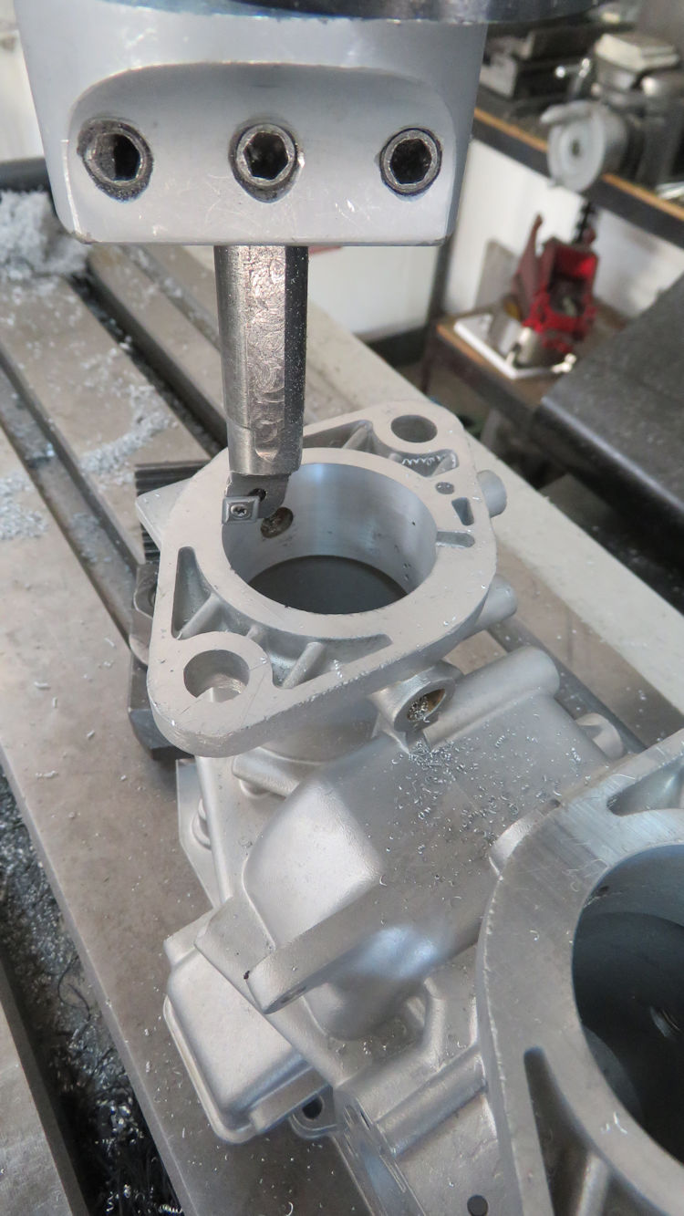
Corey machined the worst of the carbs first,
removing
just enough material to eliminate pitting
All carbs were then machined to precisely the
same
throat diameter
New butterflies will now be made to
precisely fit the new bores
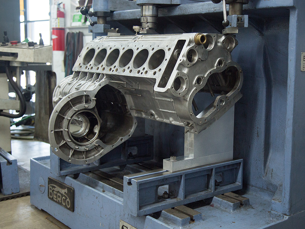
Align honing the engine block
To be continued!
Align honed to perfection
Jake examining the Miura
body after media blasting
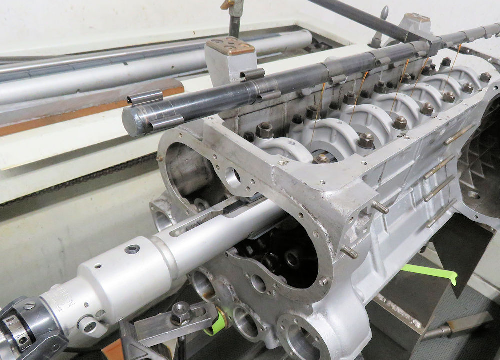
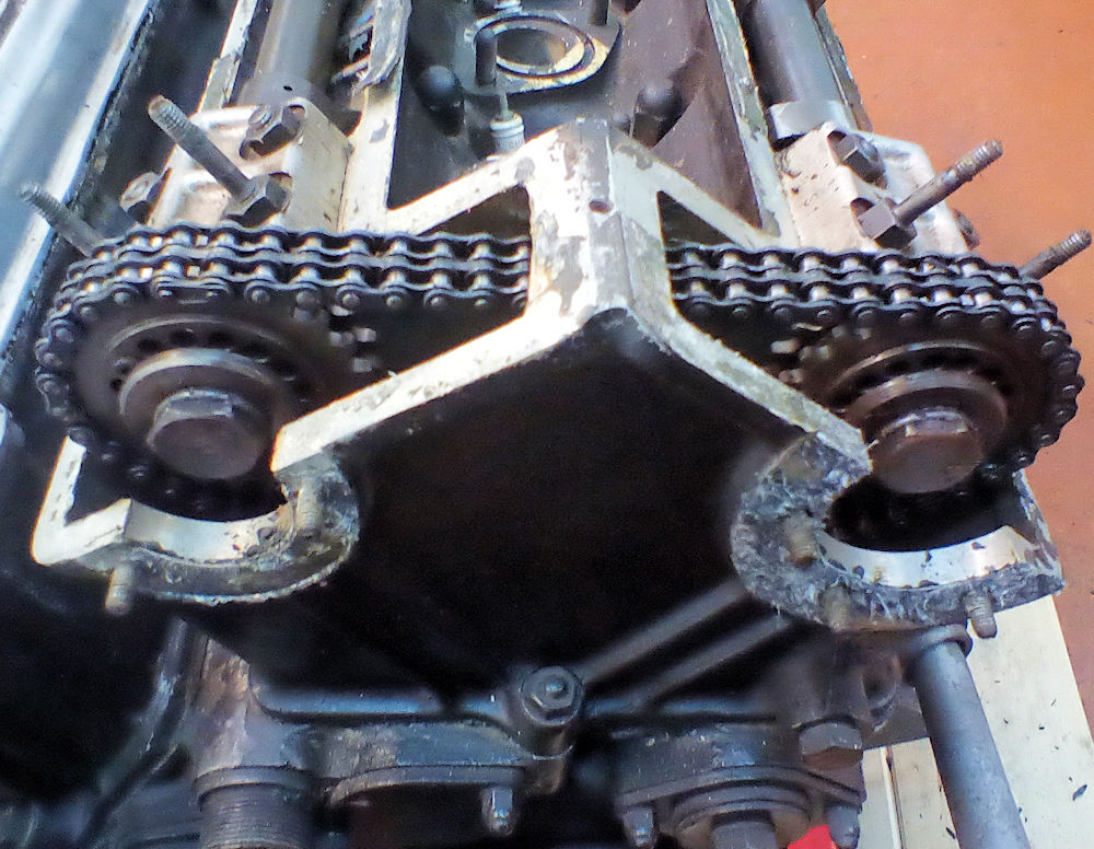
Update report - February 9, 2020
This week's
update is all about camshafts! We had the cams measured and
tested and I am delighted to say that we could not have
received a better report card. With no discernible wear, all
that was required was a light polish of the lobes and
journals and all four camshafts are now in pristine,
virtually 'as new' condition.
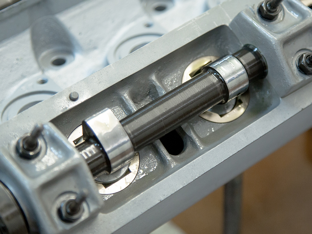
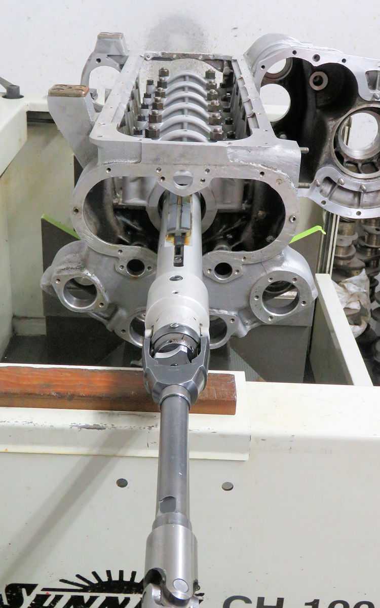
Before the cylinder heads were
disassembled, we noted that the camshafts were very
difficult to turn in the cam saddles. In fact all four cam
tunnels required an align hone, which you can see Corey
performing in the photos below the camshaft report.
Following the align hone, cam saddle clearances were a
consistent .002" across the board and the cams now spin
freely.
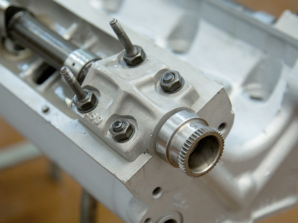
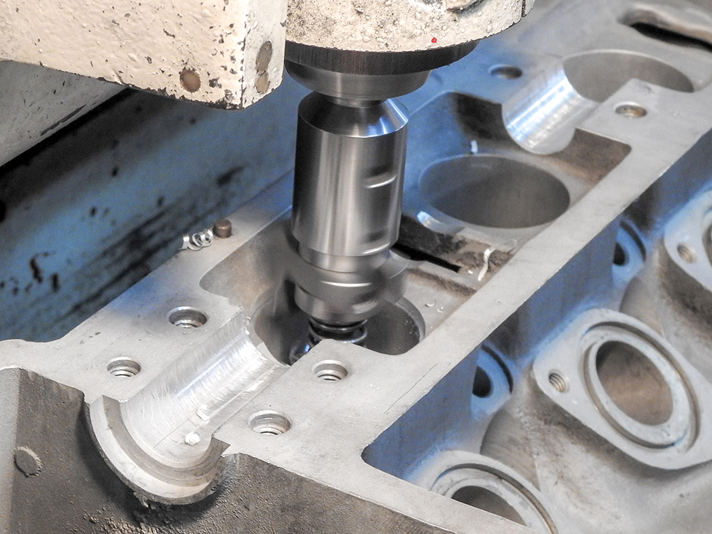
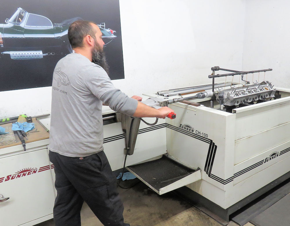
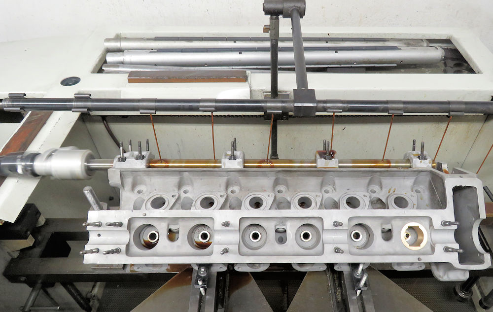
Corey align honing the cylinder heads
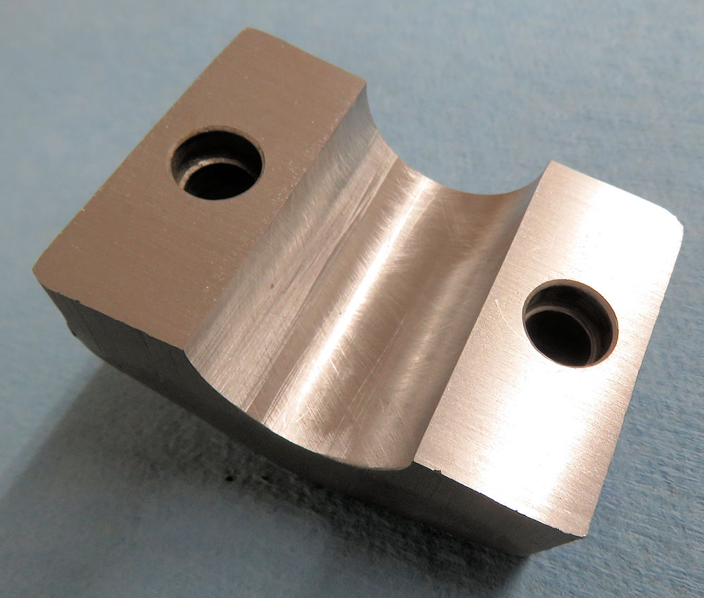
One of the cam caps after the align hone
was completed
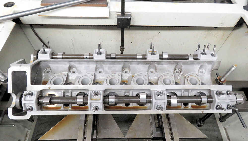
Trial fitting cams and measuring clearances
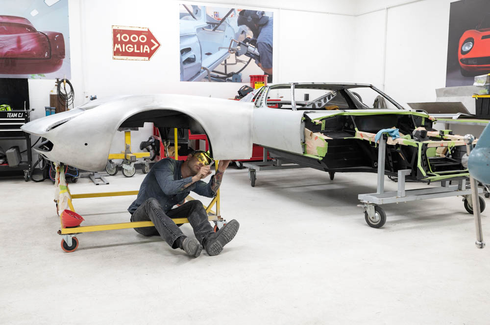
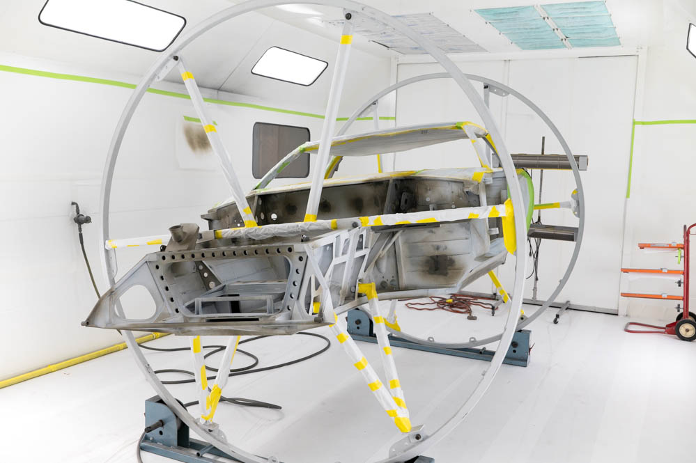
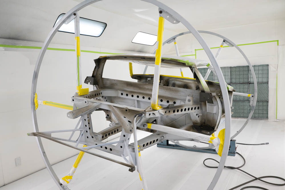
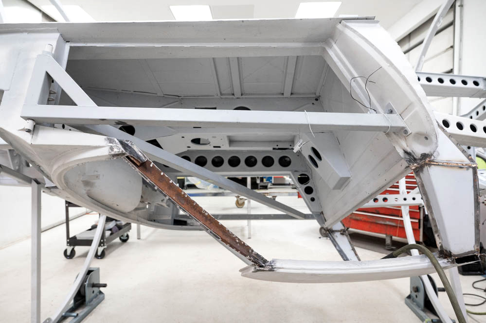
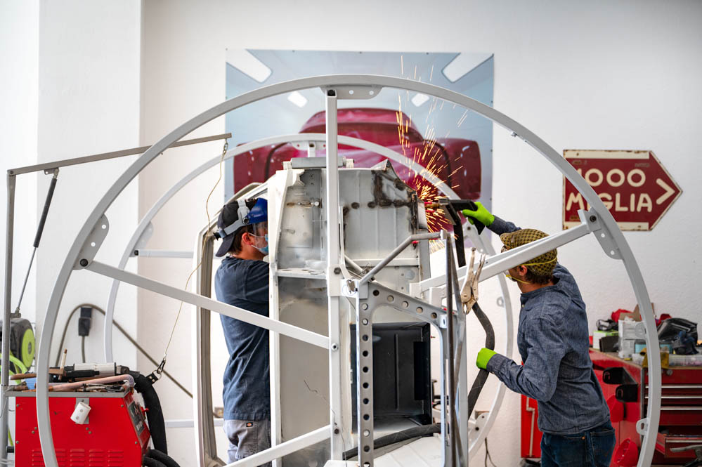
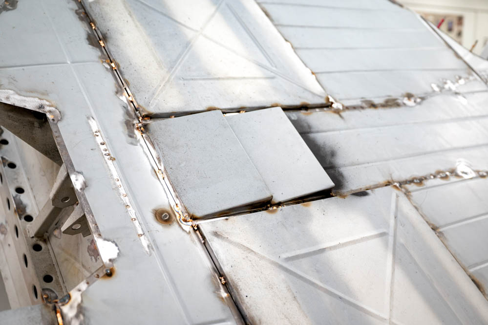
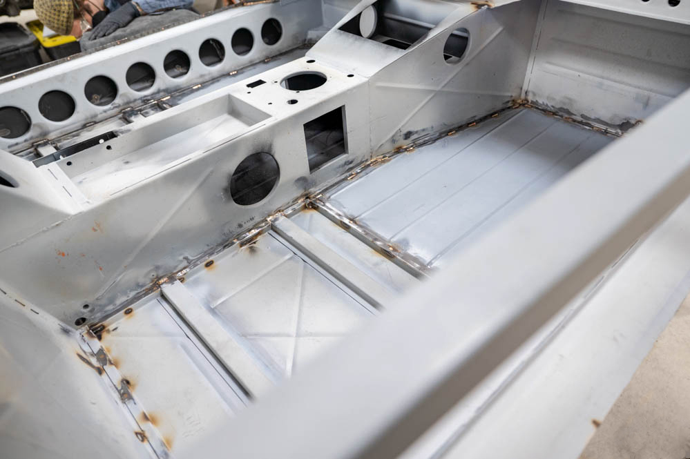
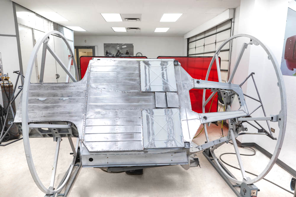
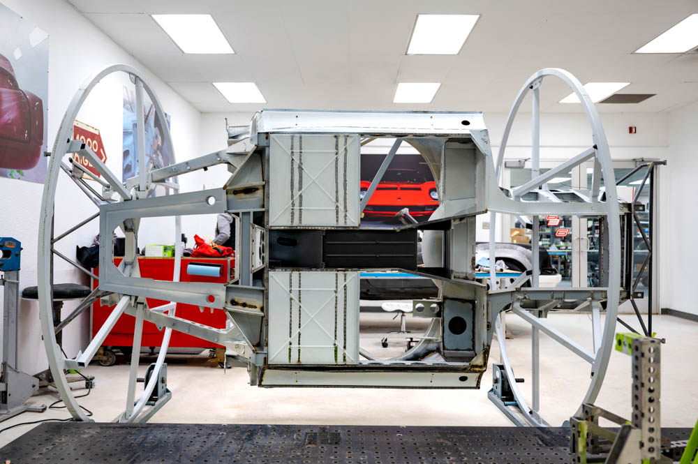
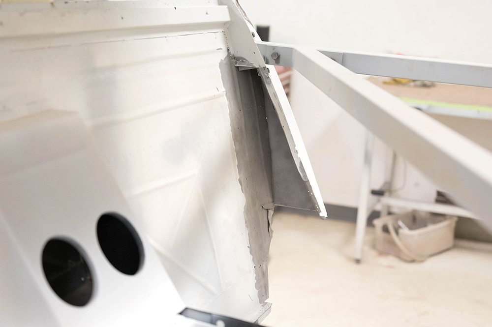
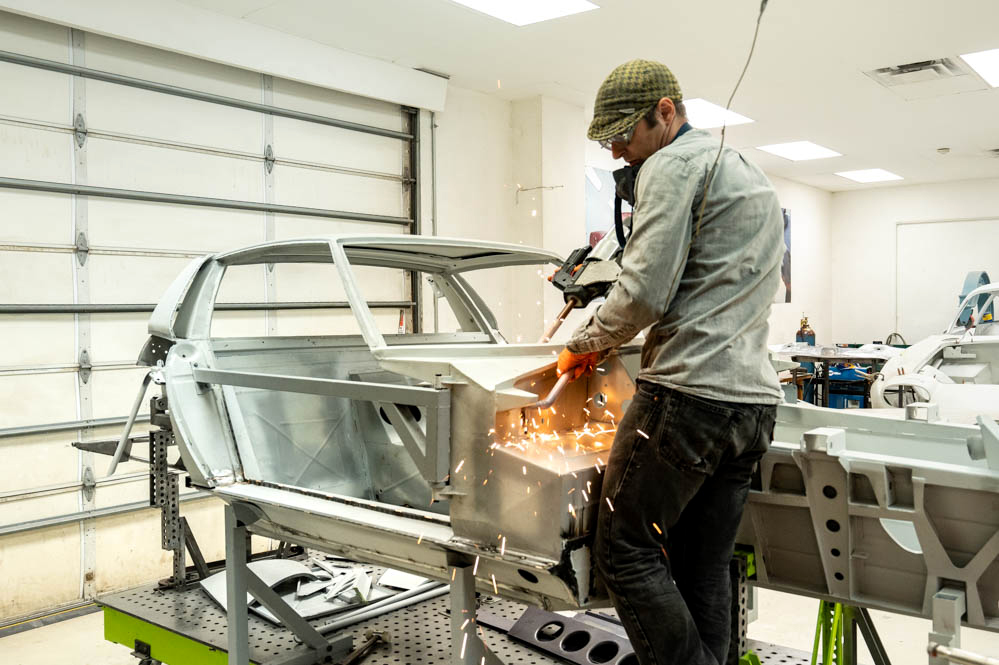
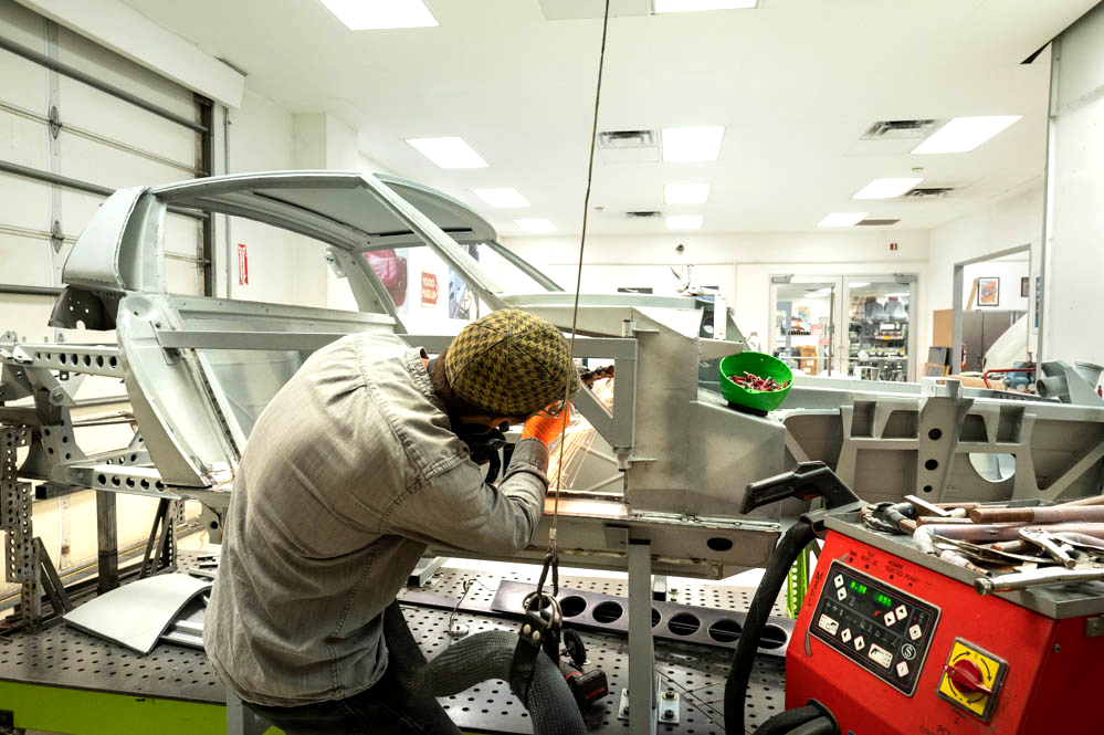
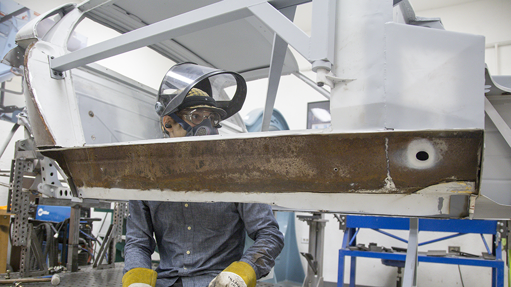
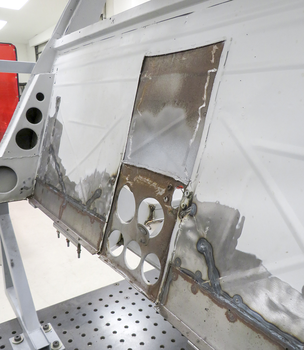
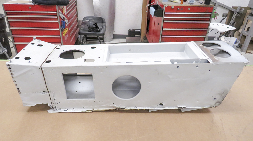
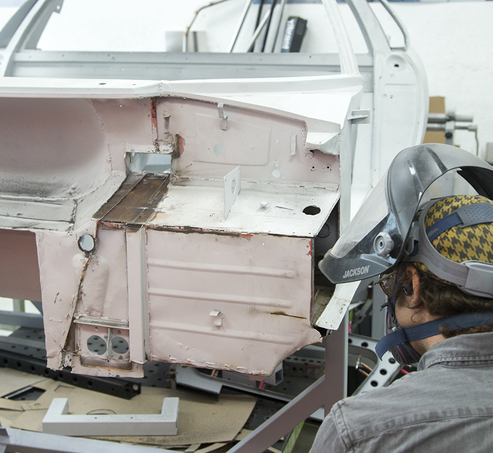
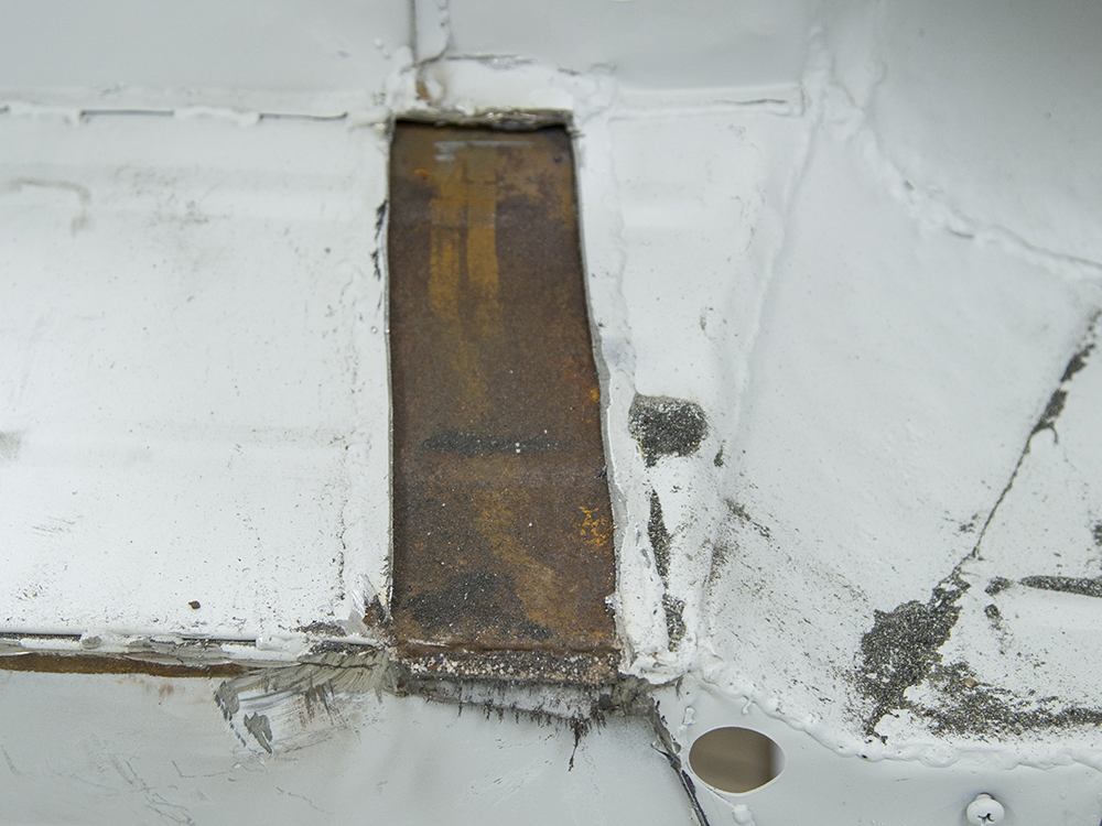
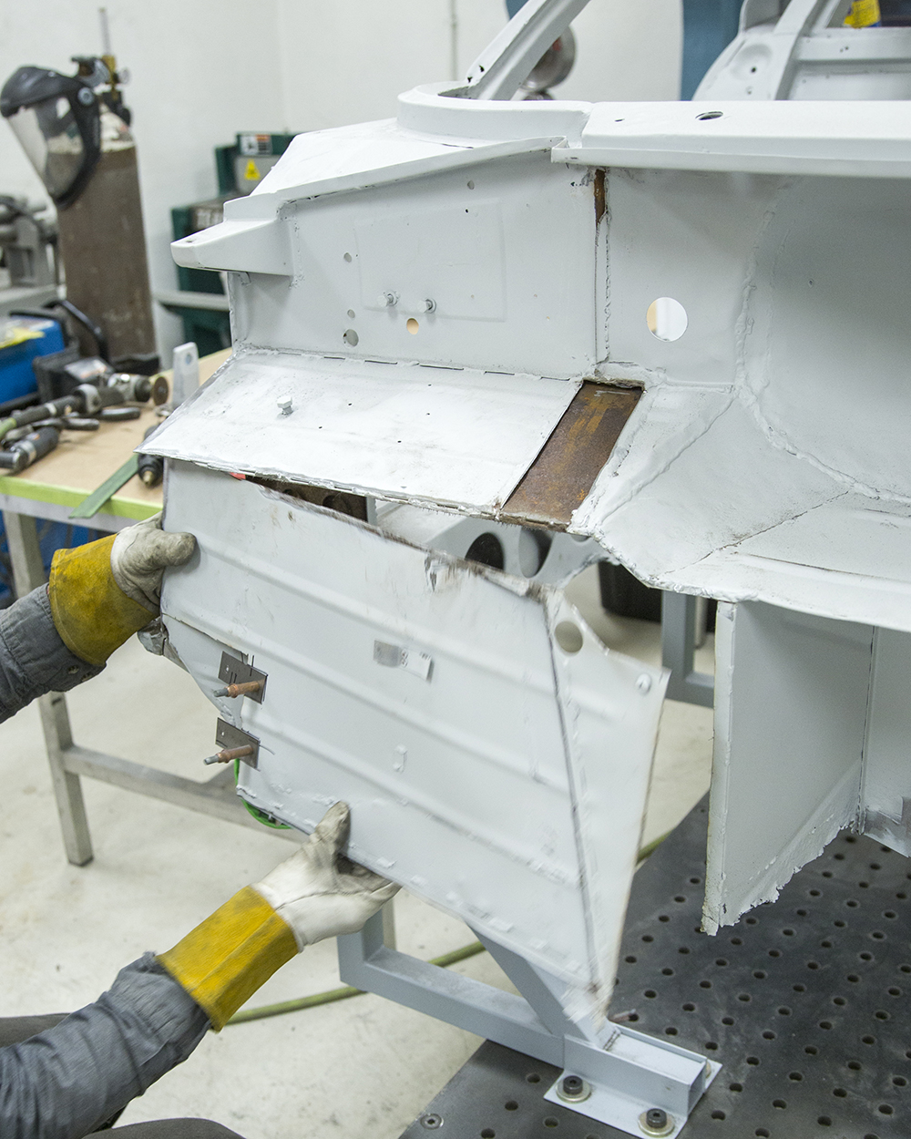
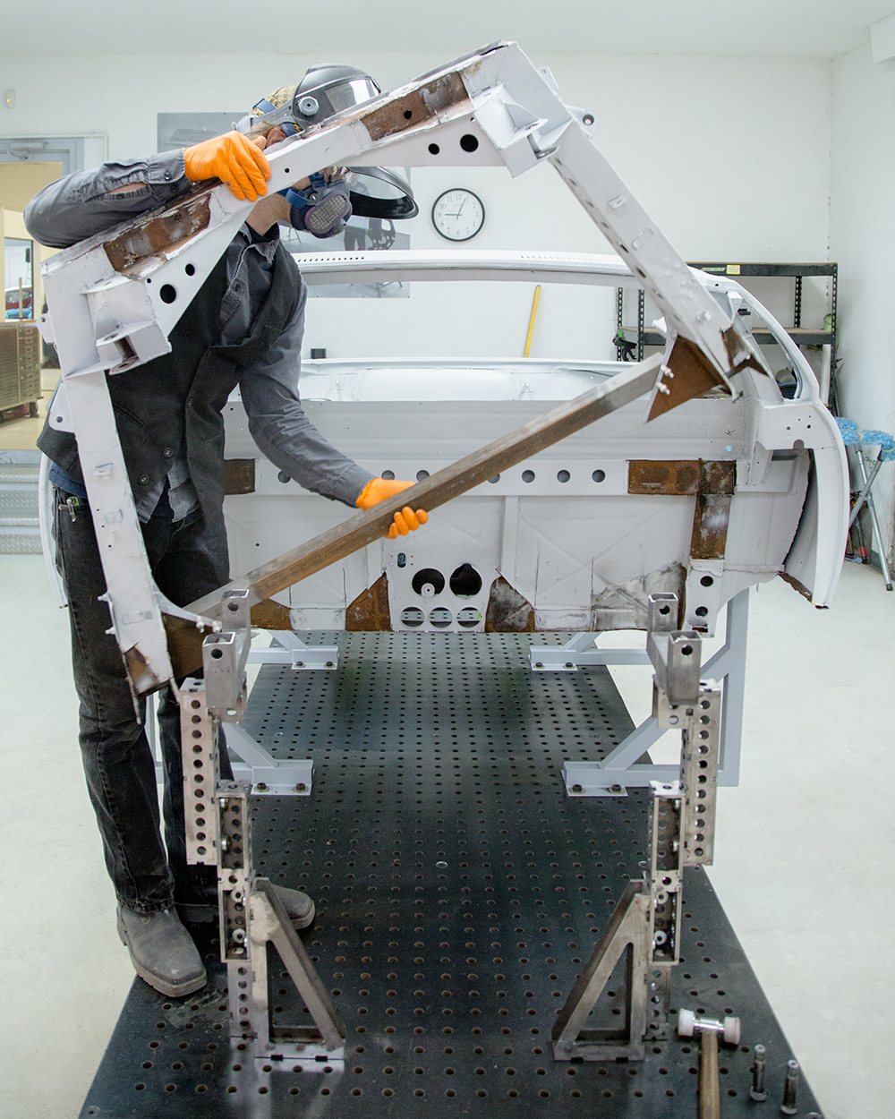
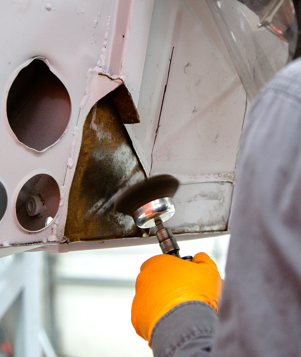
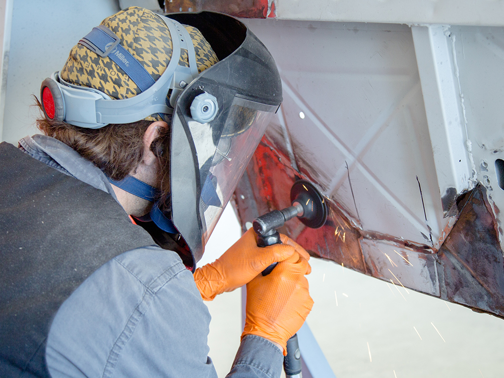
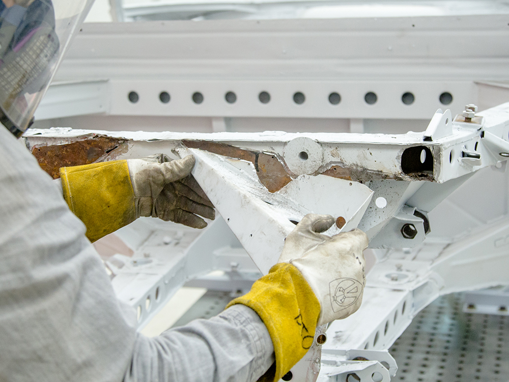
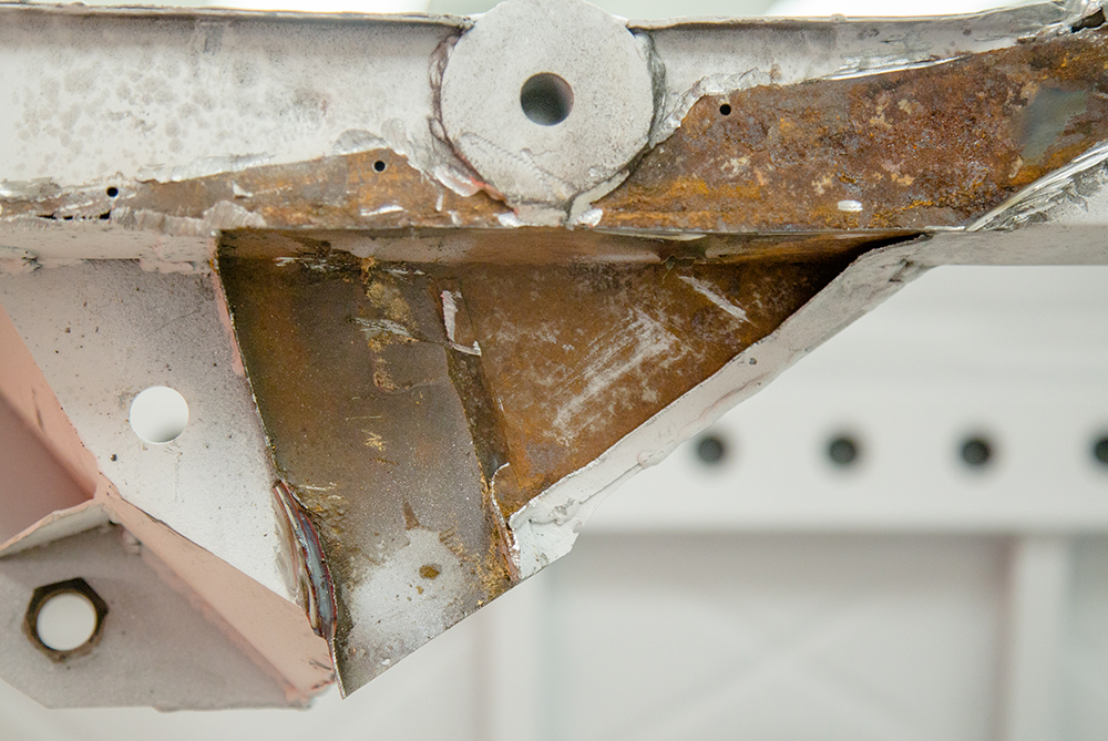
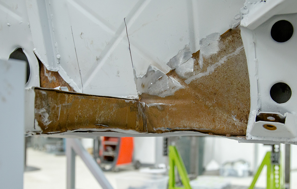
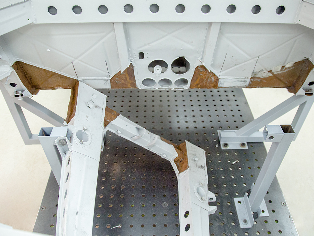
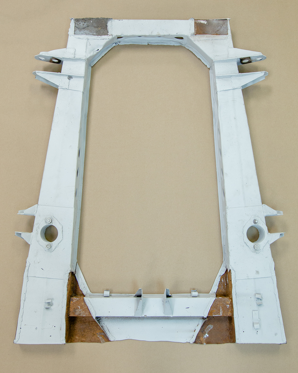
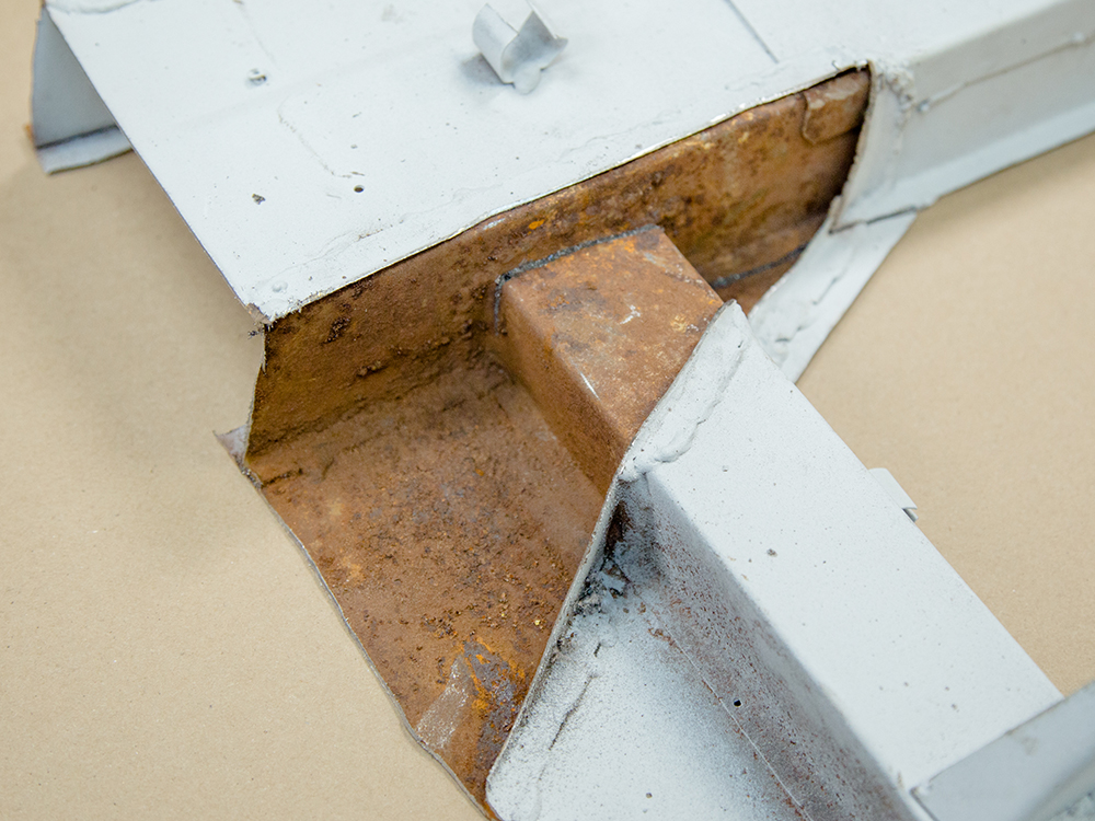
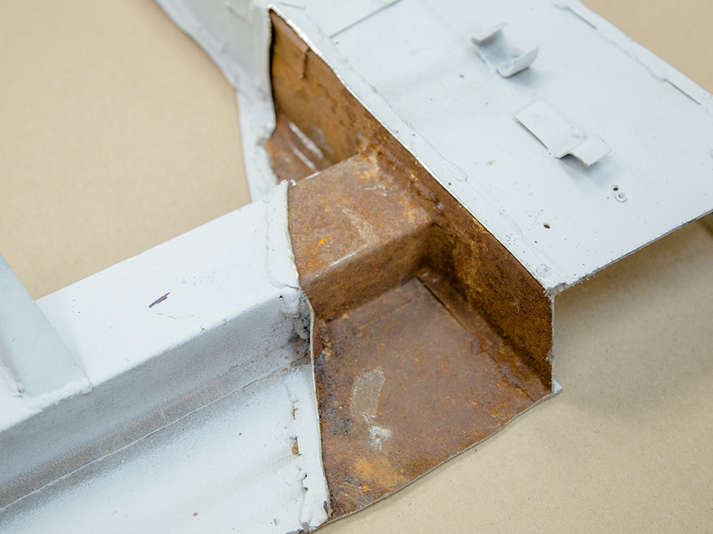
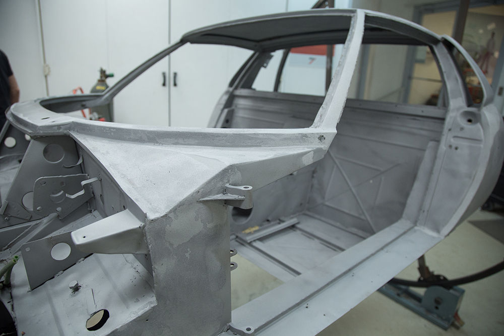
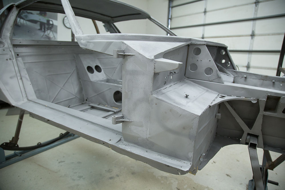
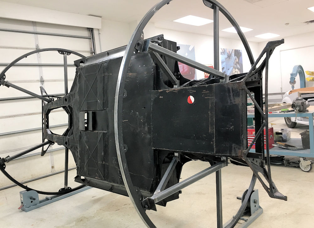
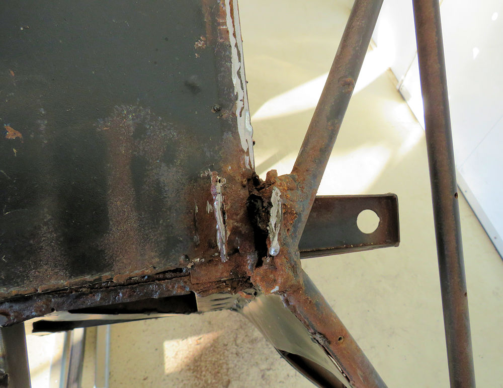
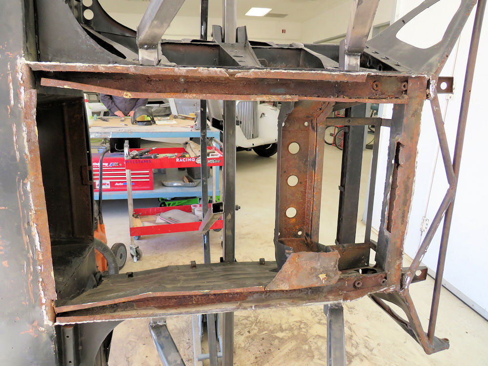
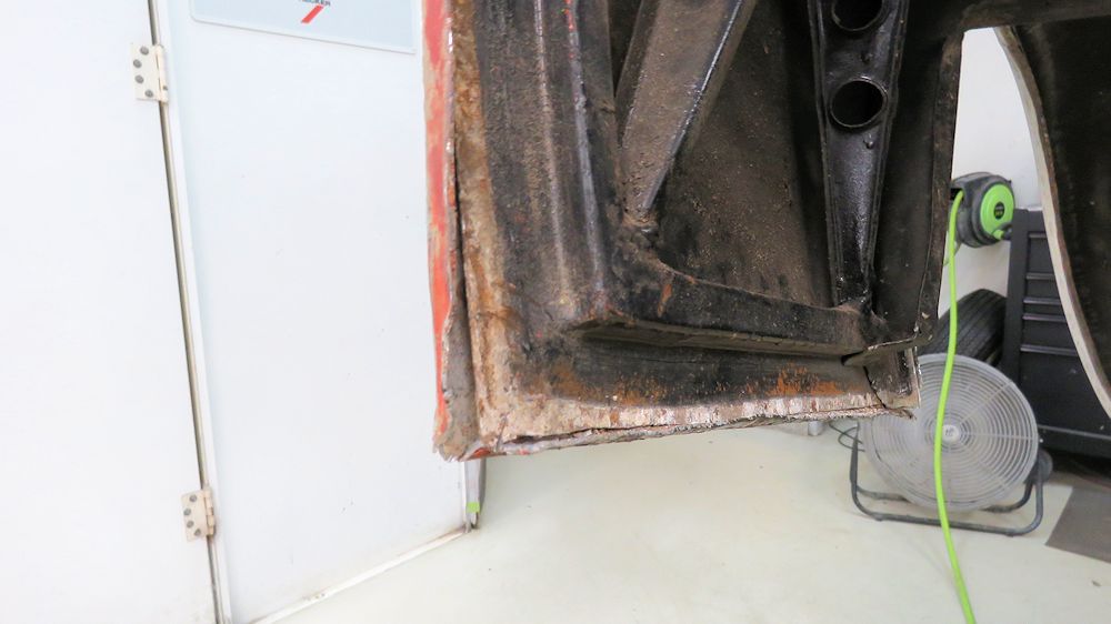
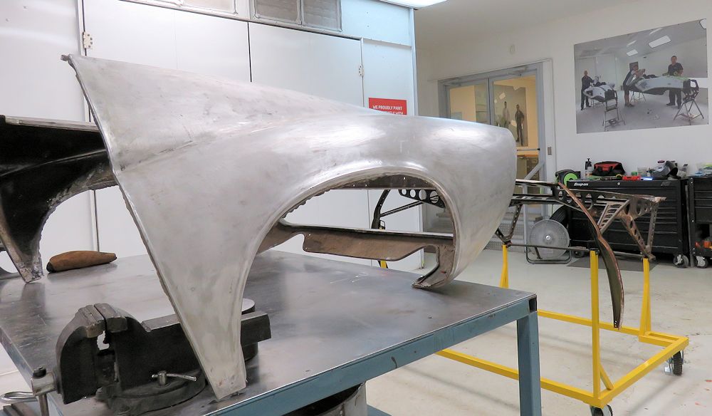
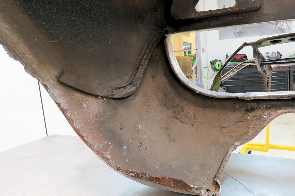
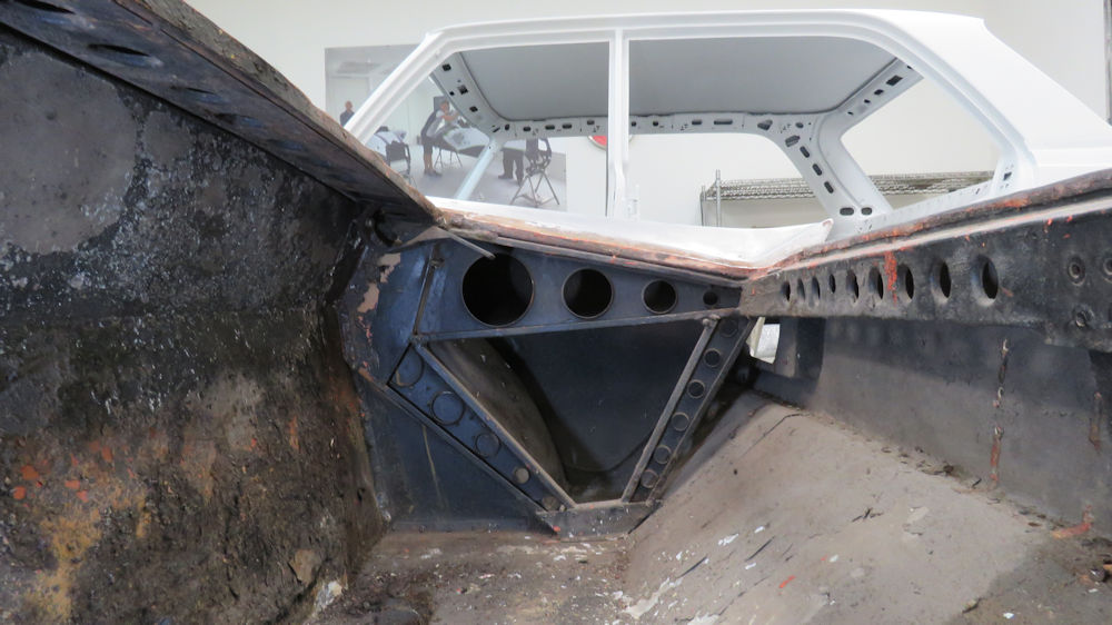
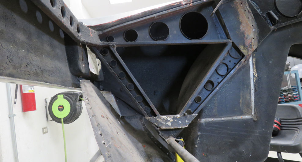
Jake explaining
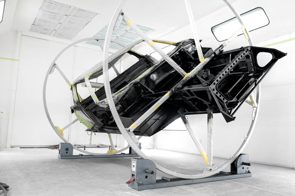
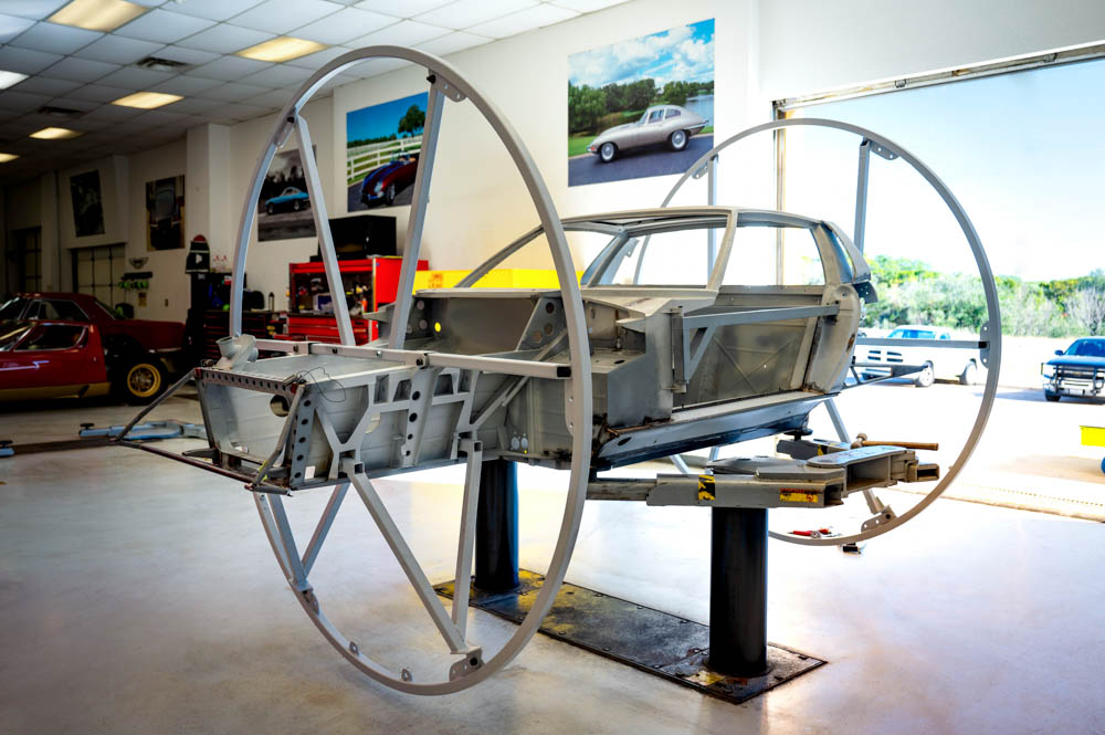
corrosion issues with the Miura body shell
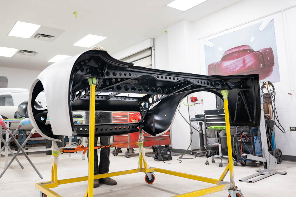
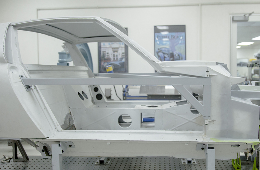
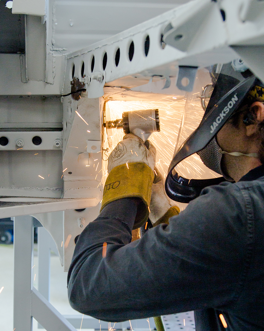
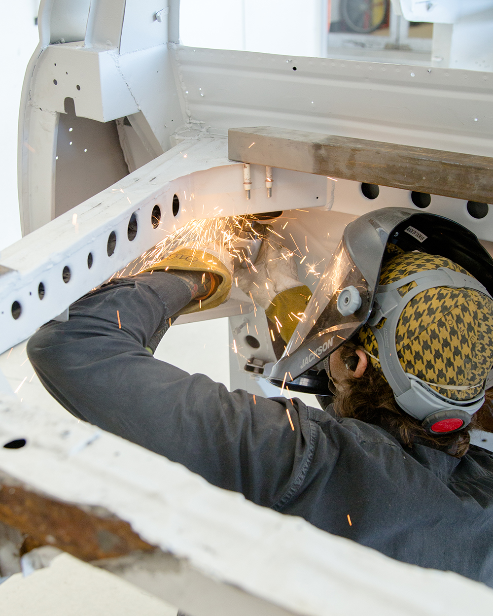
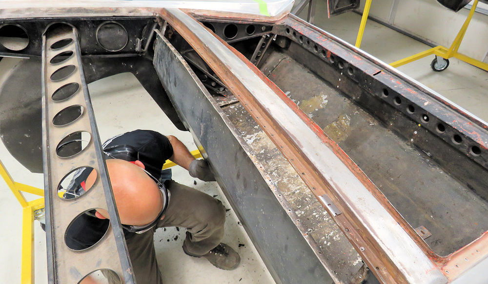
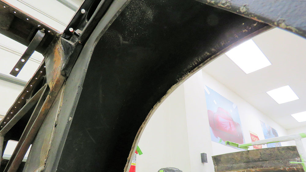
With the body now mounted on one of
the roller-hoop rotisseries, we have started cutting away
some of the obviously corroded panels prior to media
blasting everything back to bare metal. Unfortunately, some
previously installed repair panels also had to be removed
revealing some severe corrosion lurking beneath.
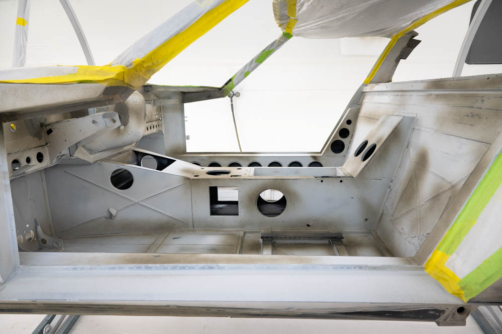
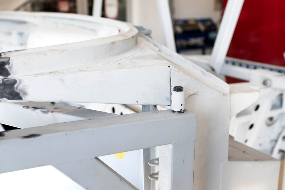
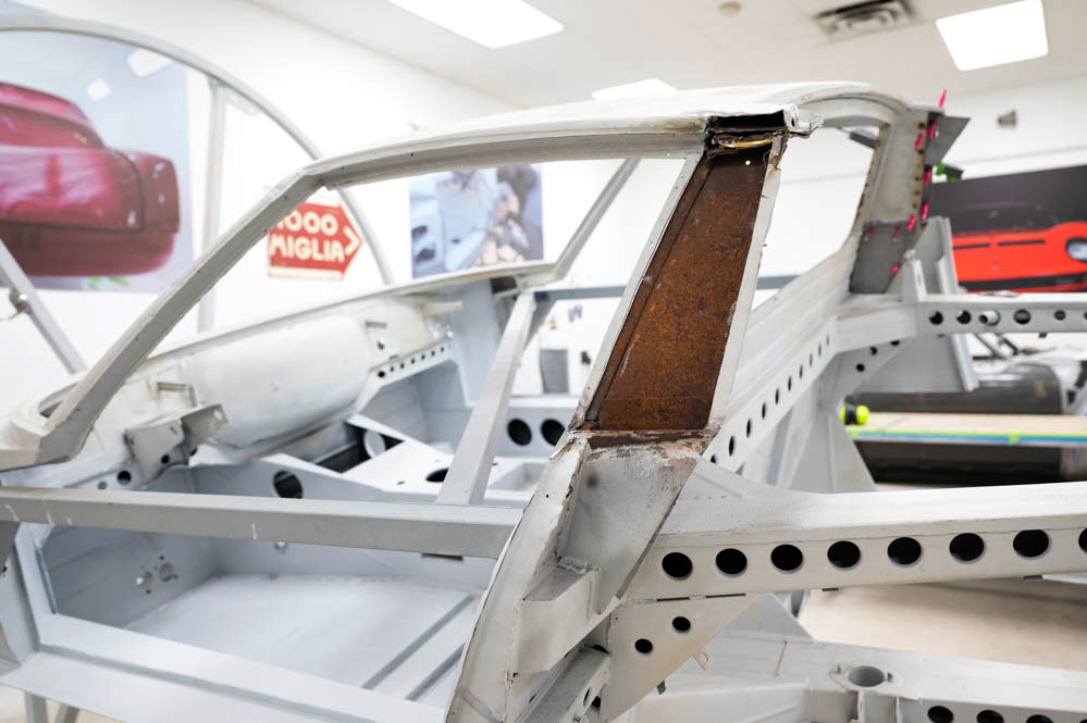
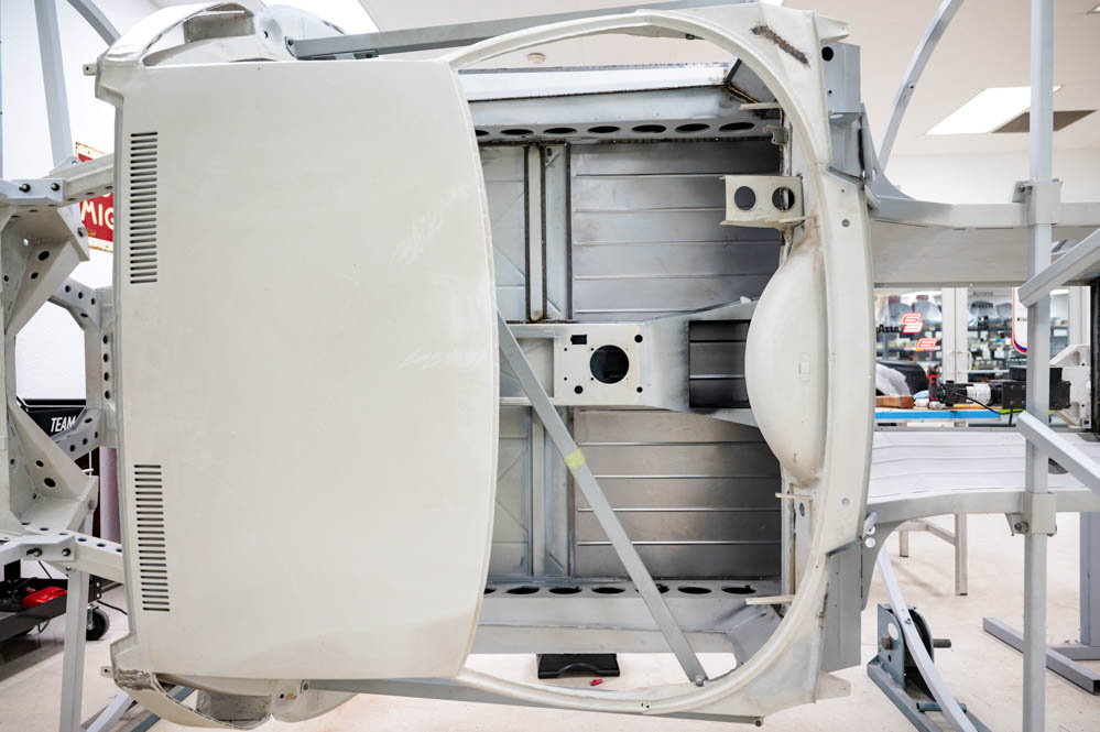
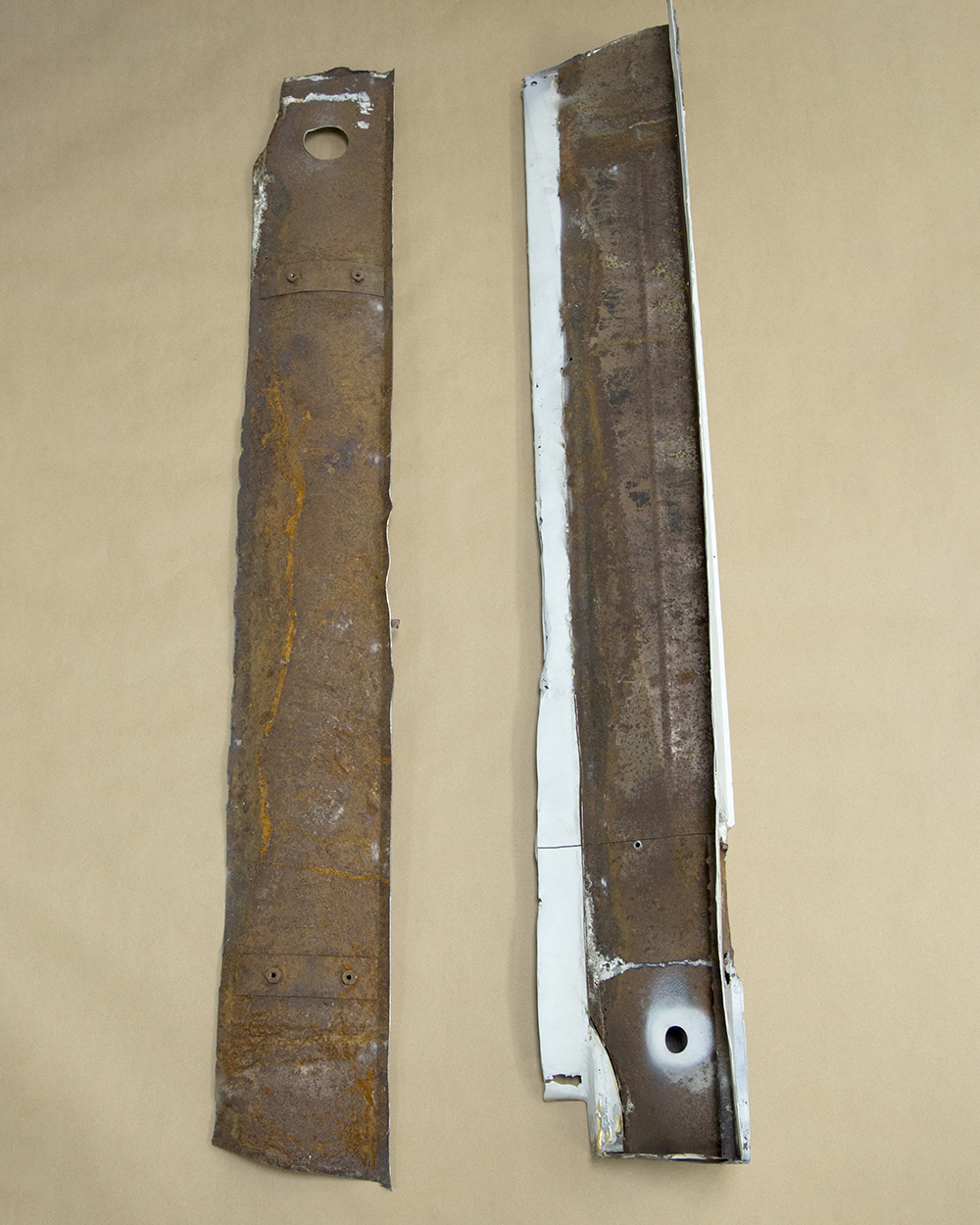
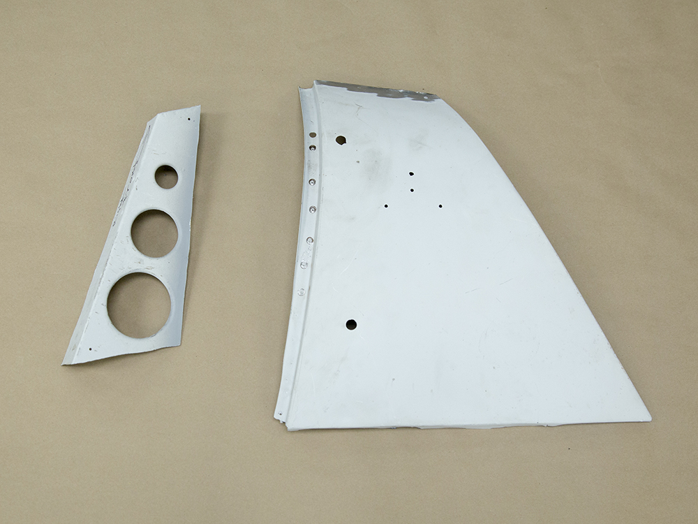
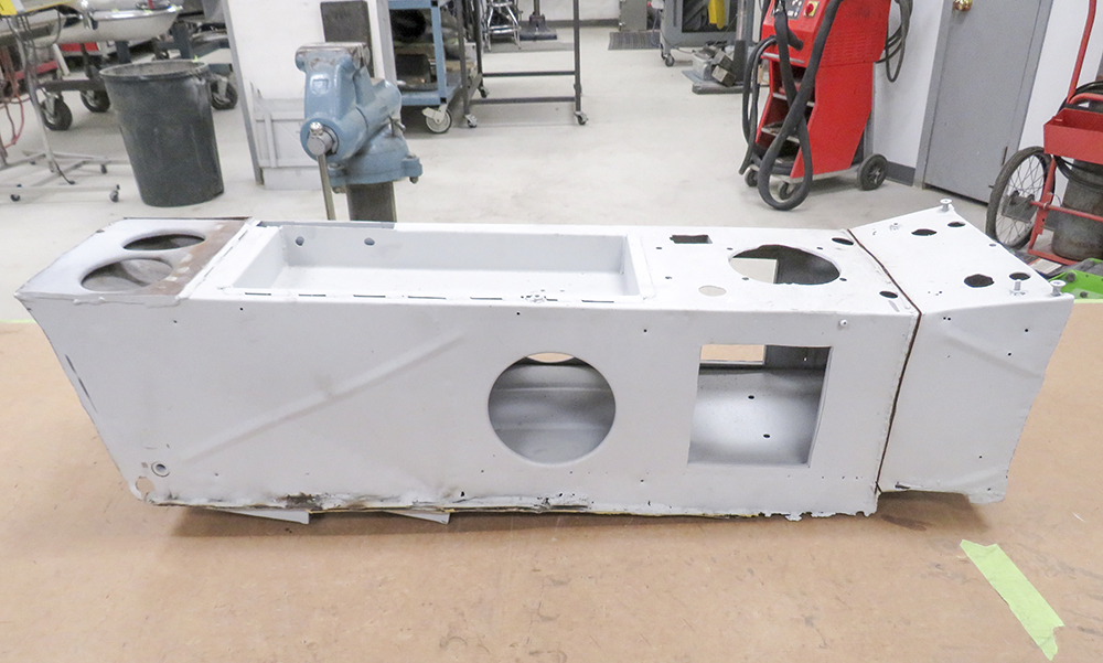
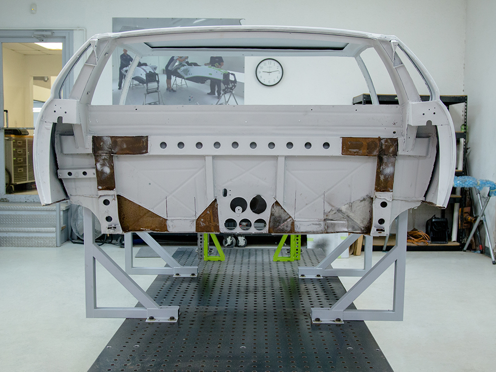
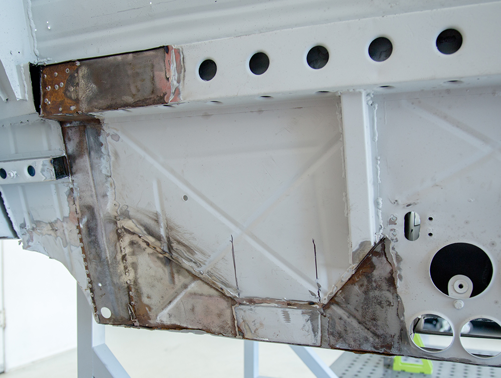
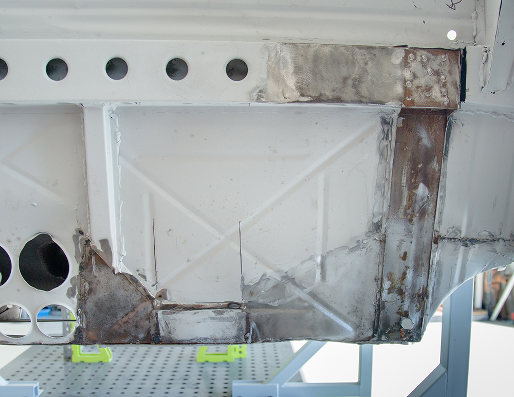
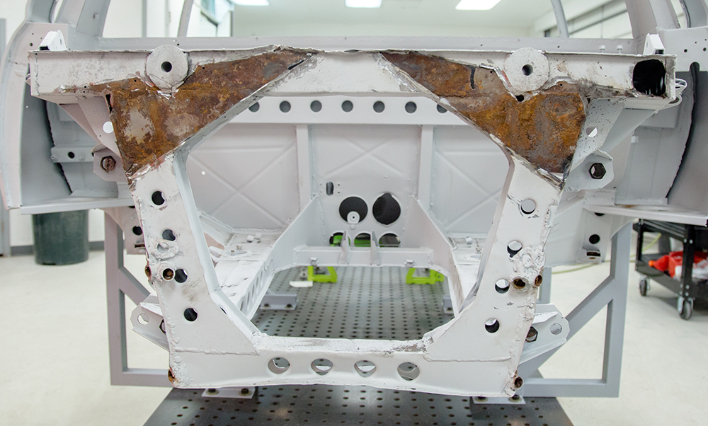
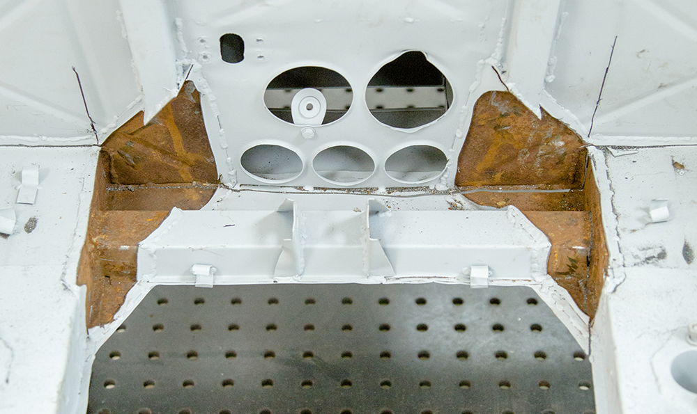
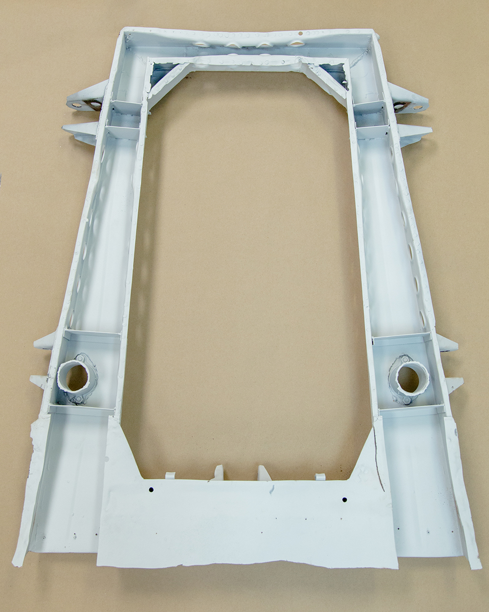
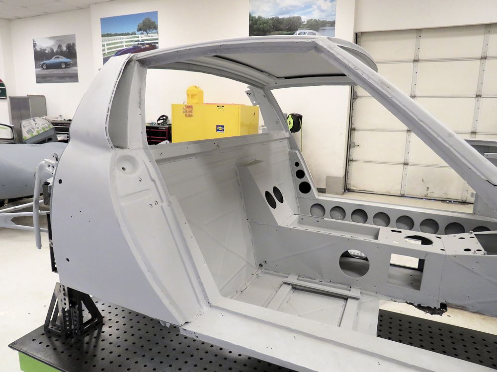
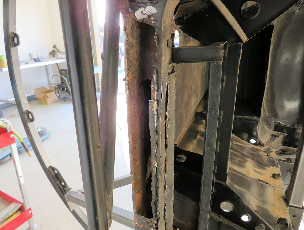
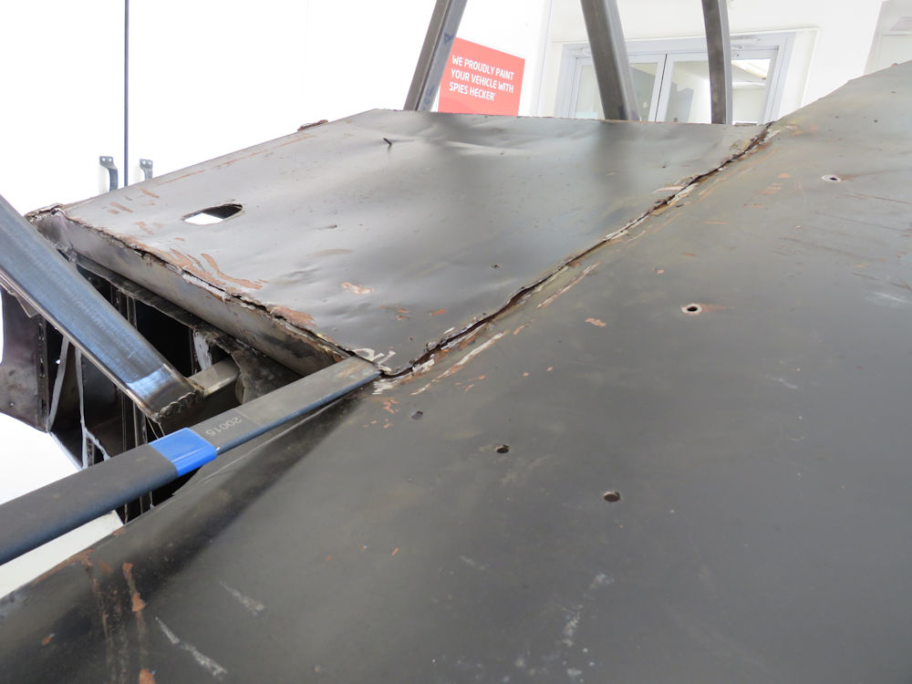
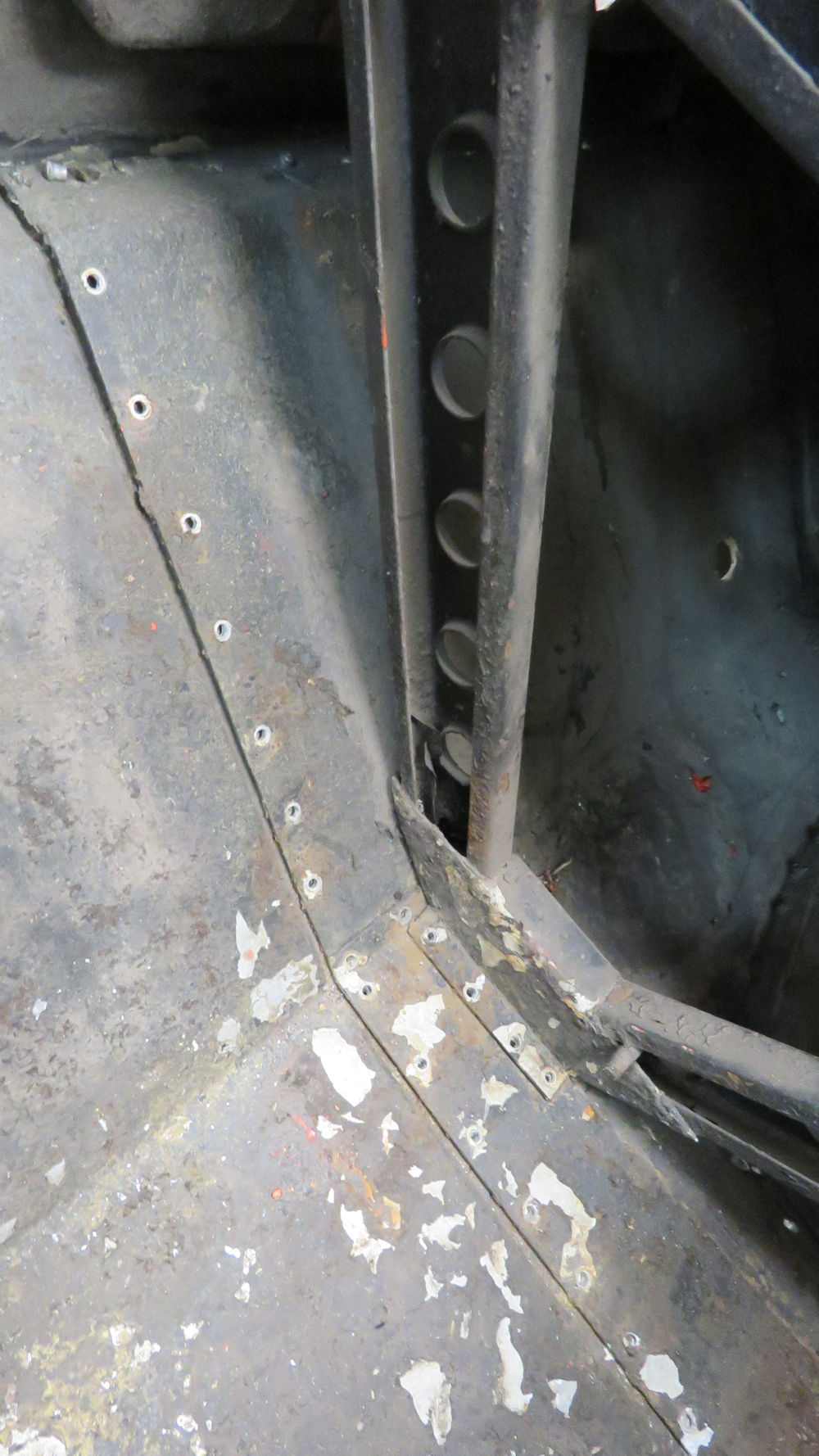
At first glance, the monocoque doesn't look
too bad
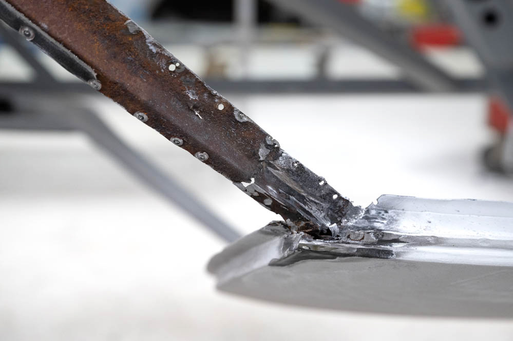
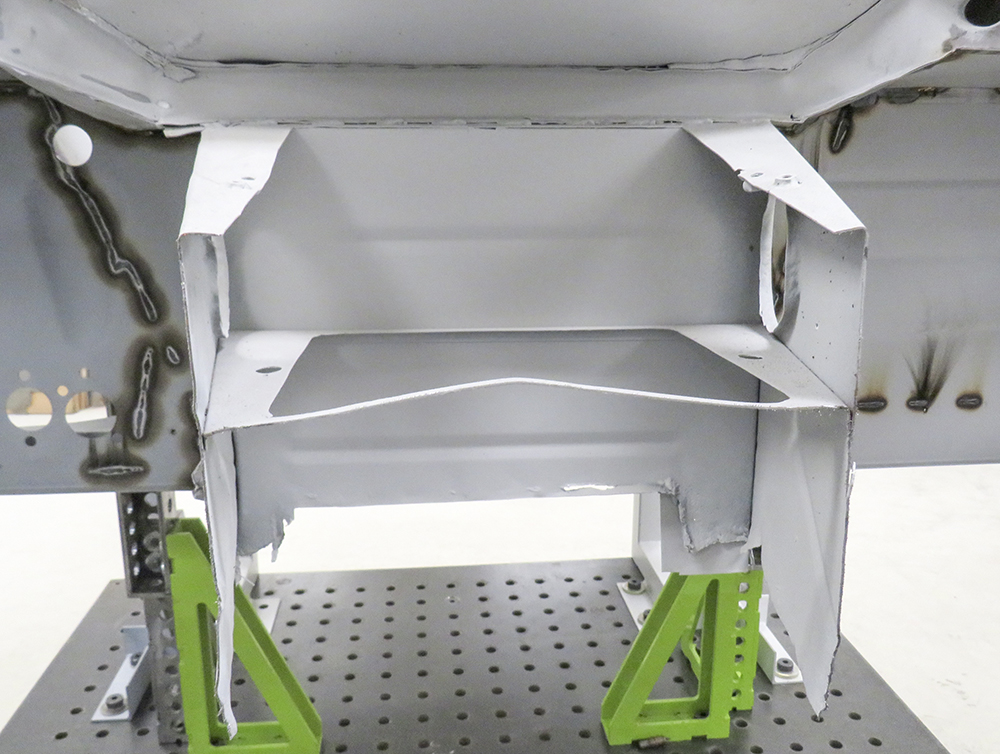
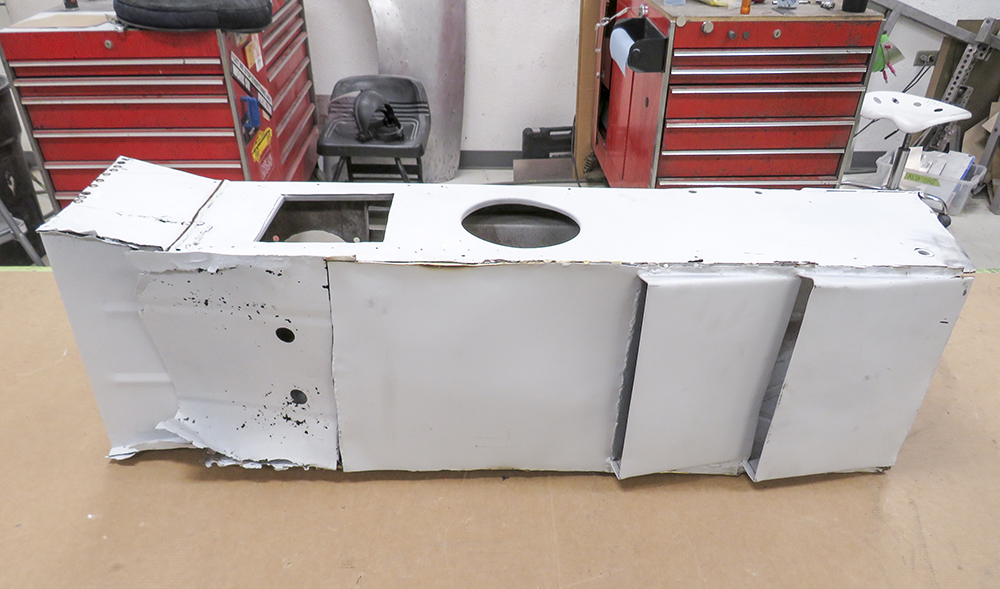
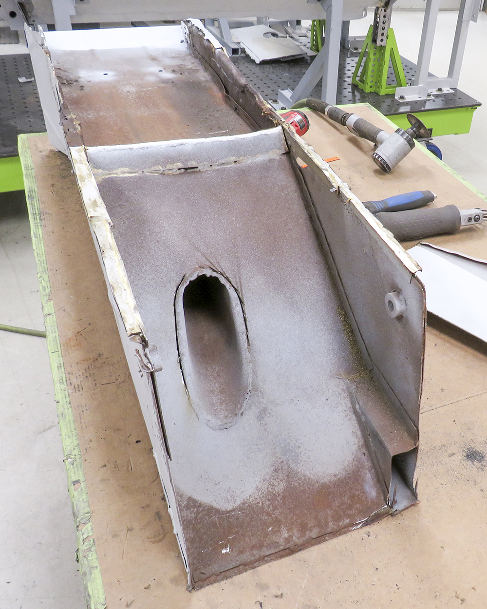
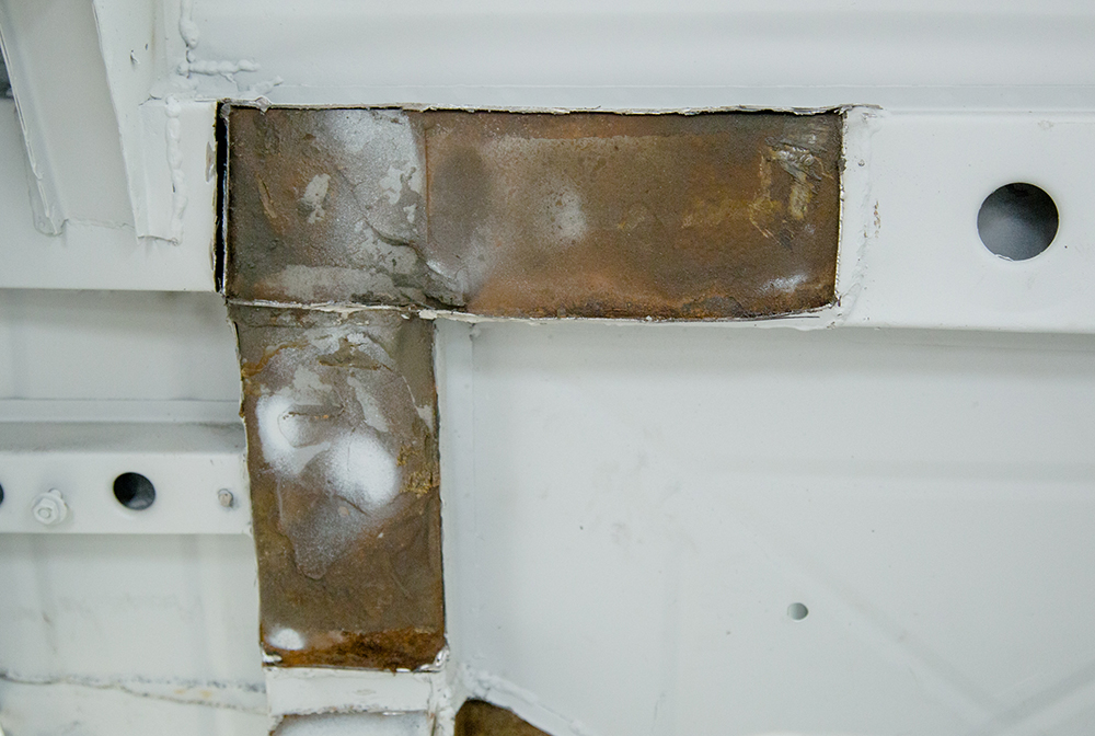
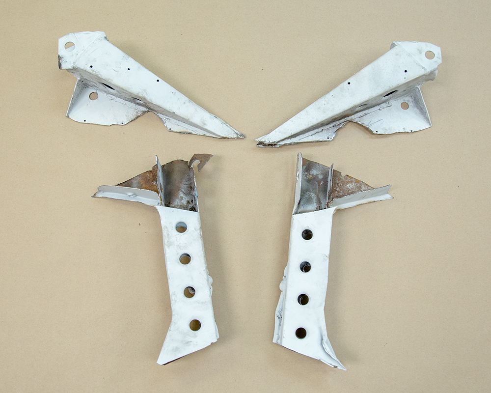
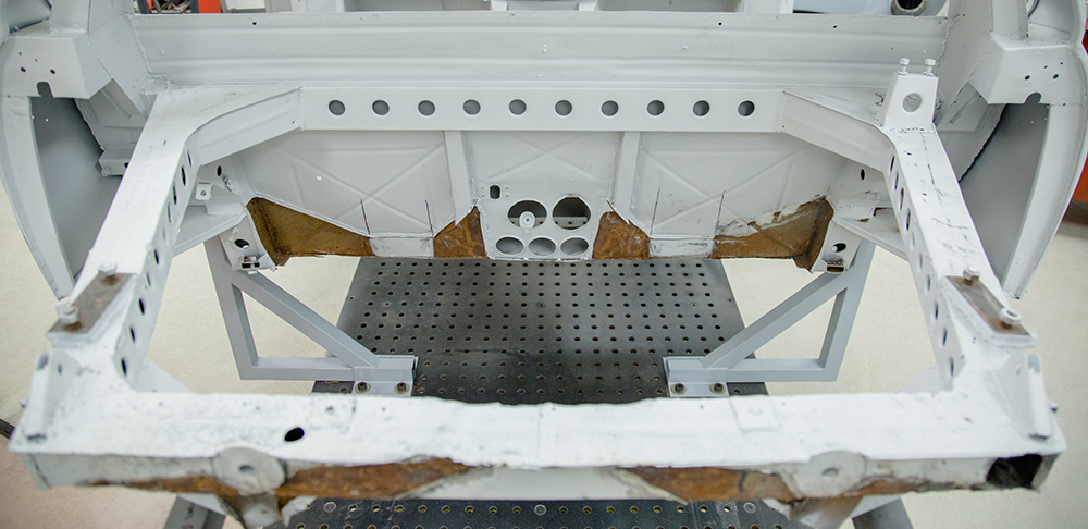
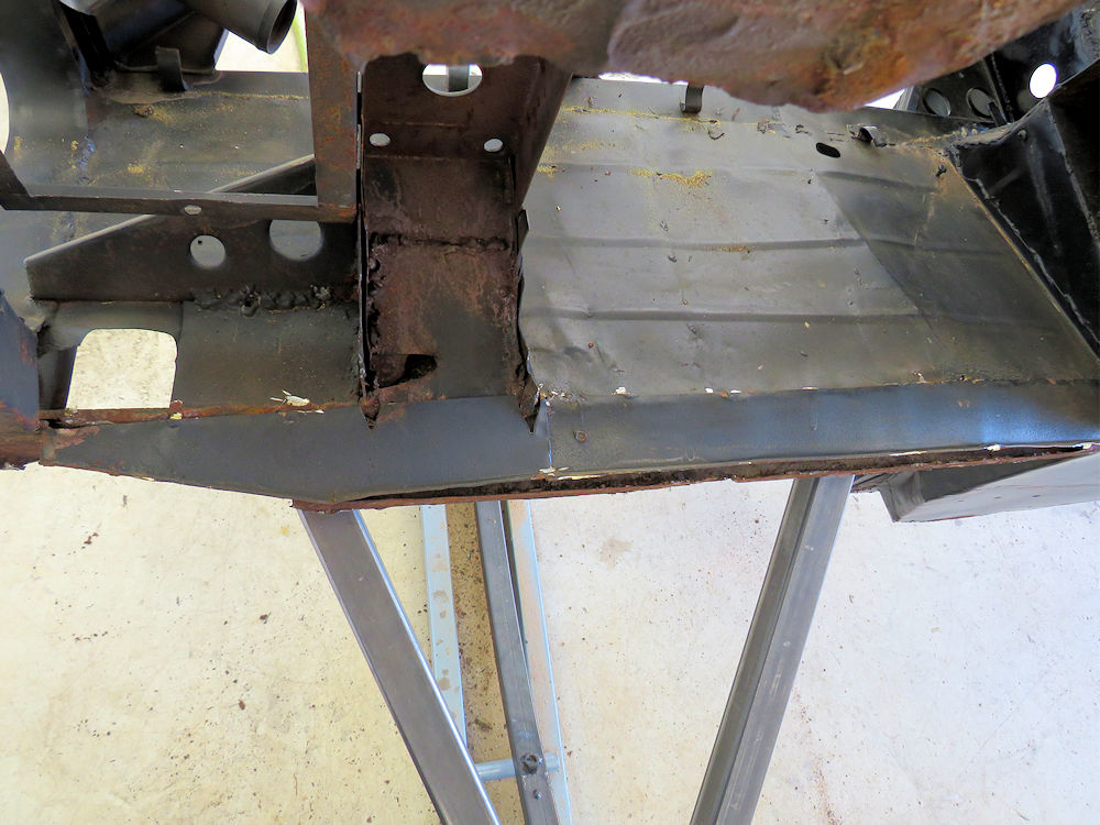
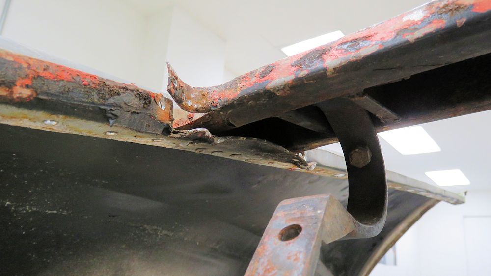
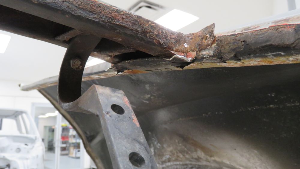
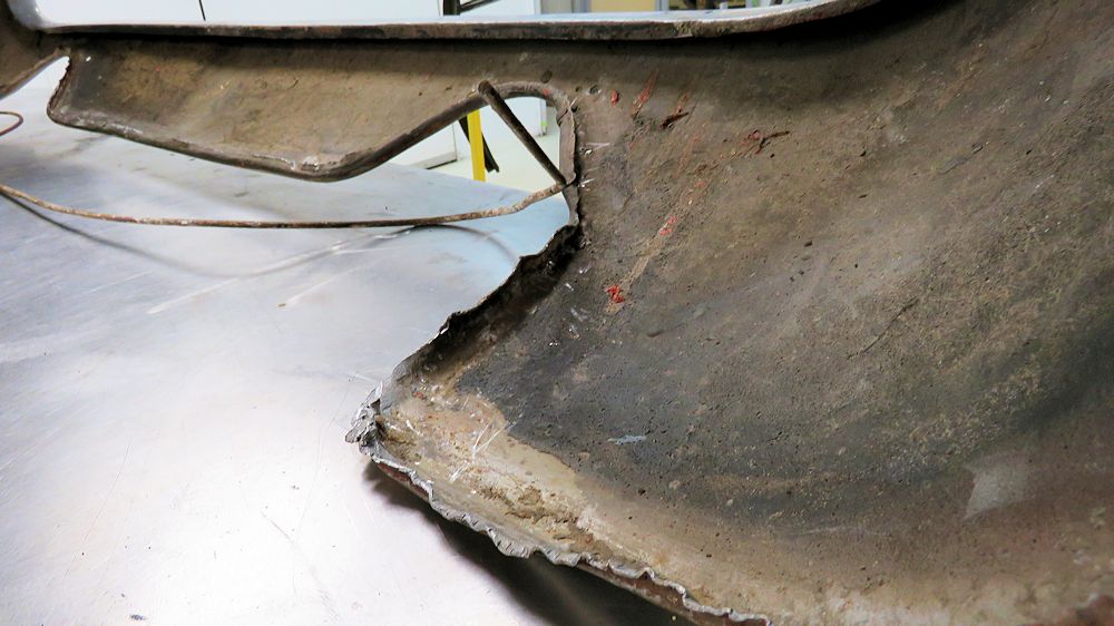
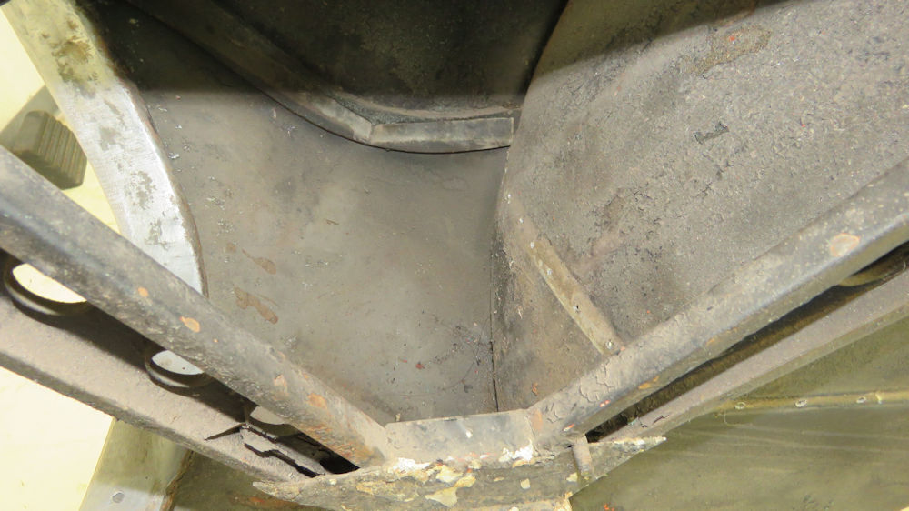
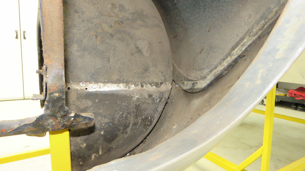
Unfortunately, closer examination revealed
some
serious corrosion issues
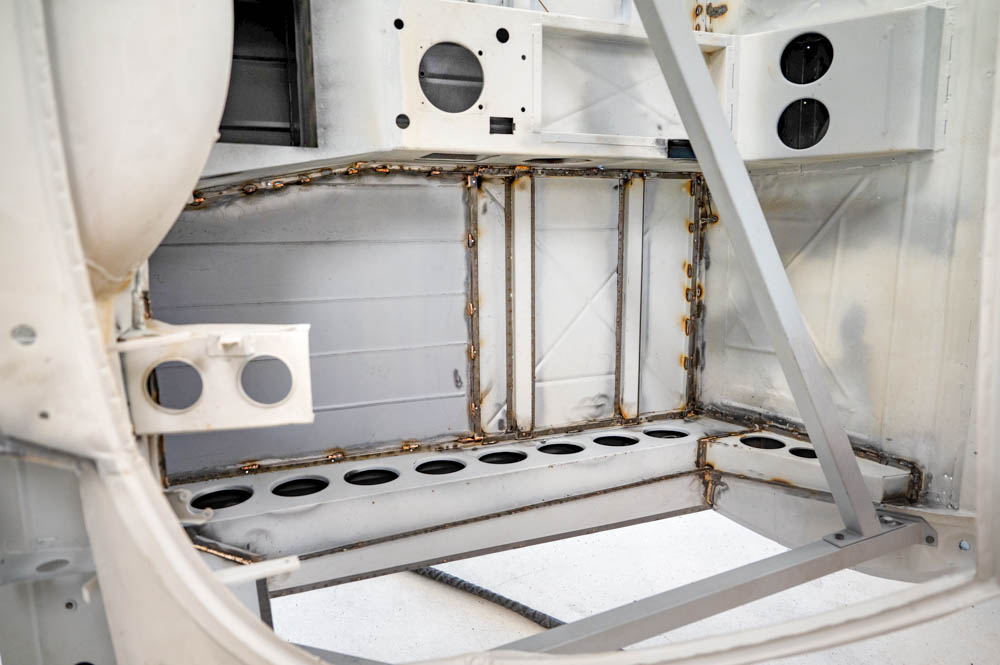
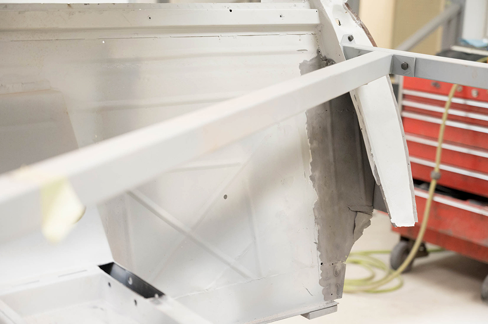
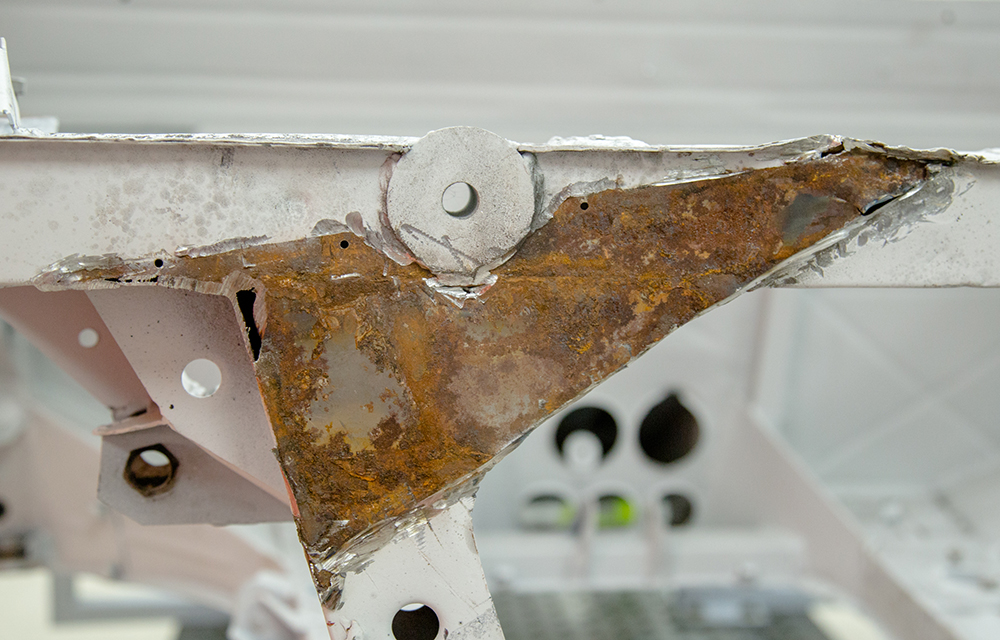
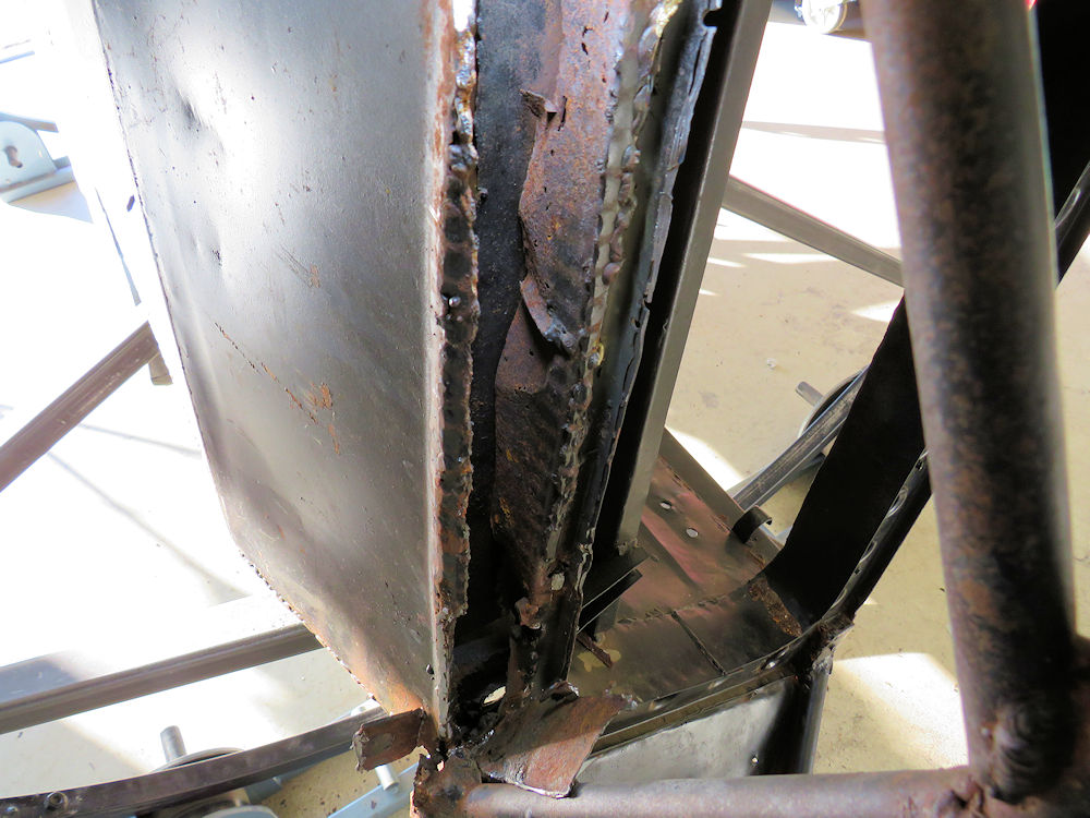
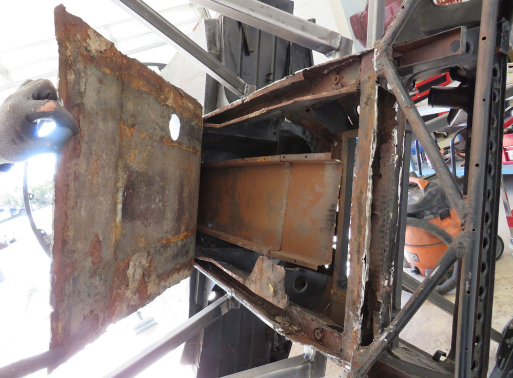
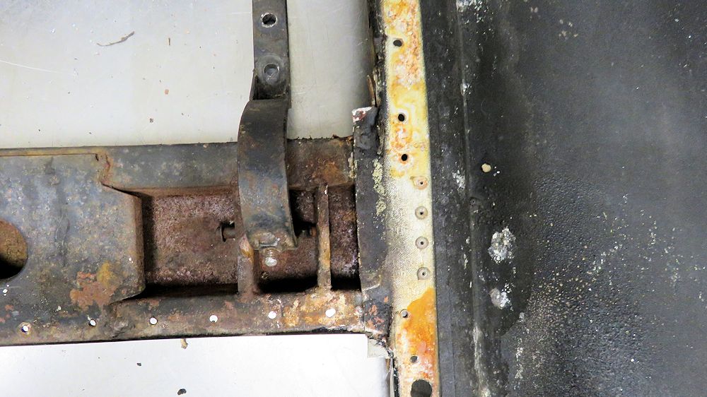
This panel had been replaced in the past
Not a pretty sight beneath
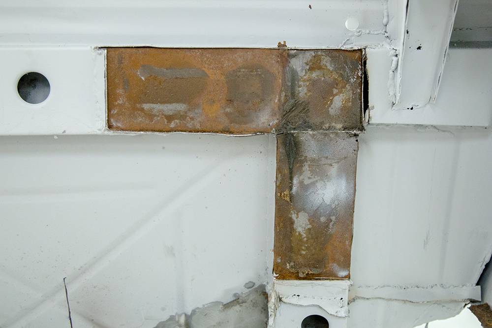
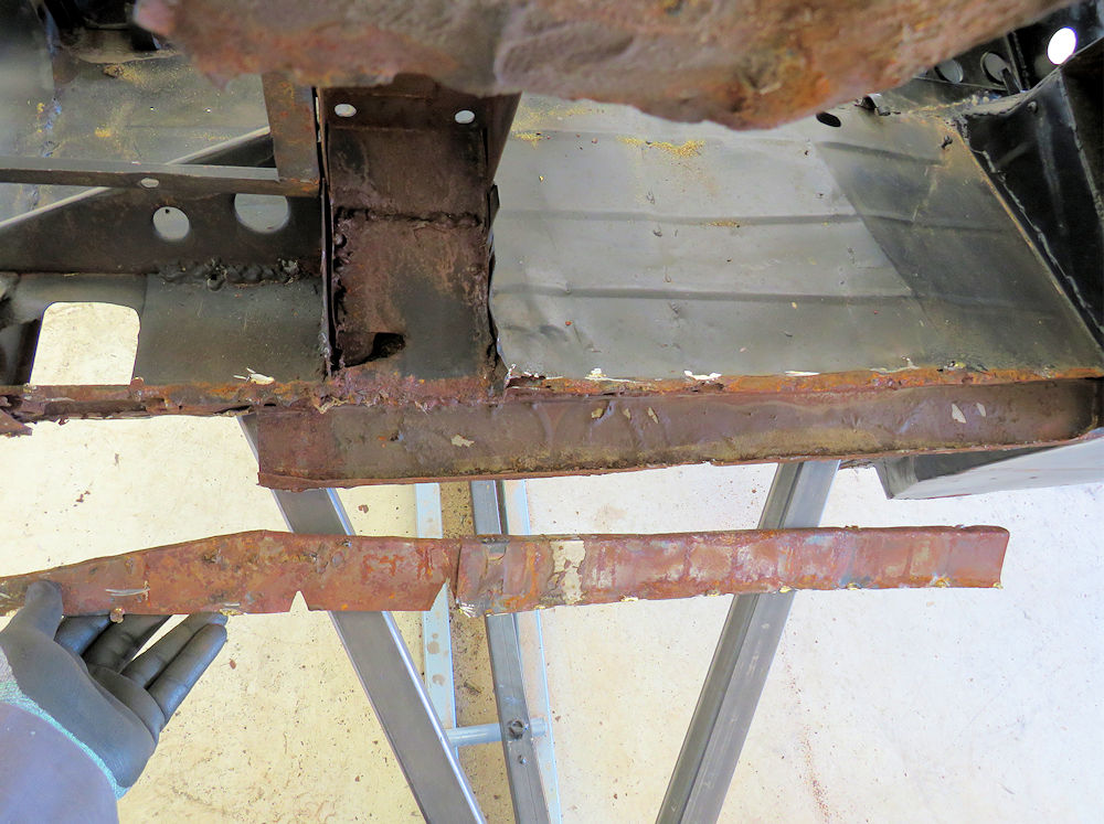
Another suspect looking repair panel
More rust lurking beneath
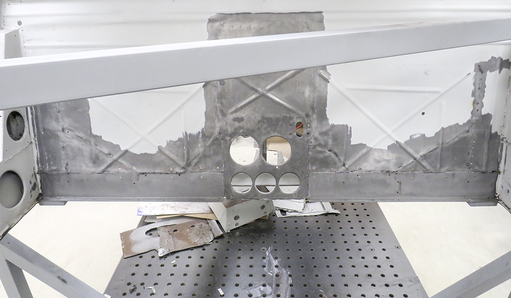
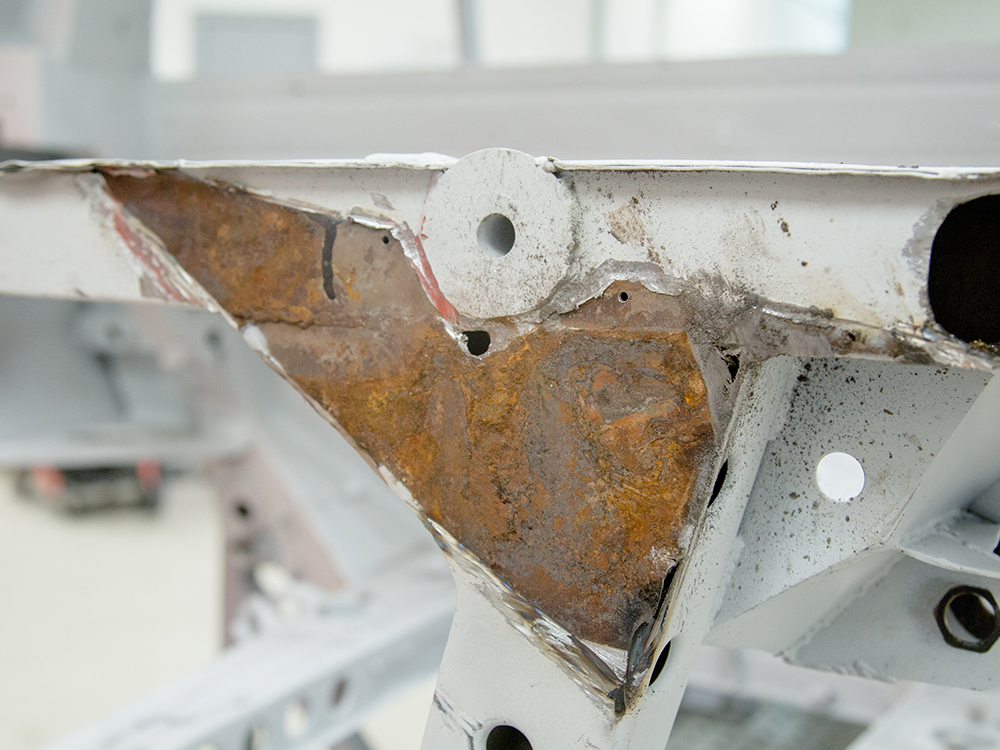
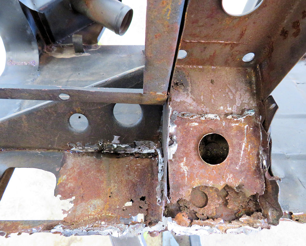
2 of the worst looking repairs I have seen in
a while
Yet more rust lurking beneath
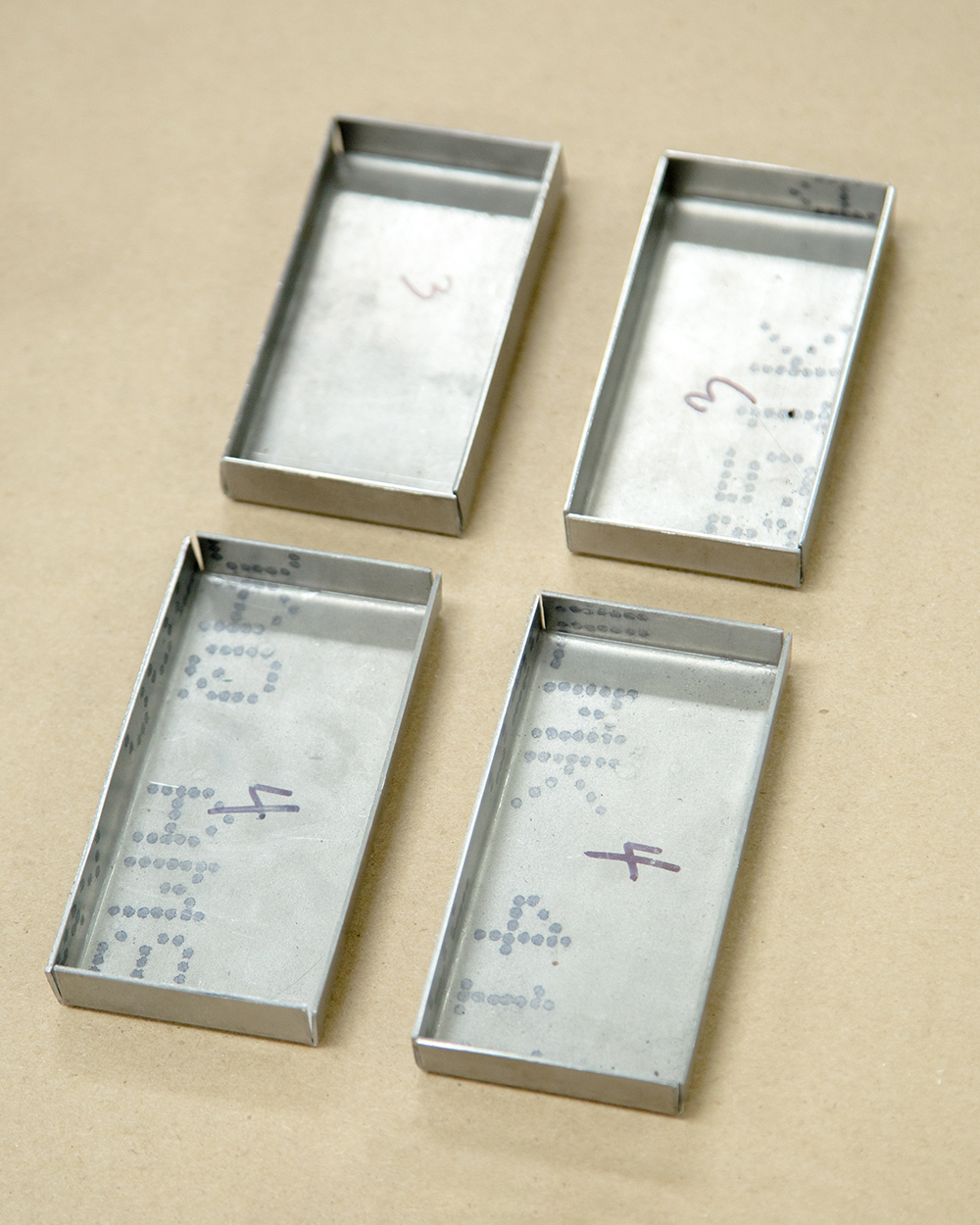
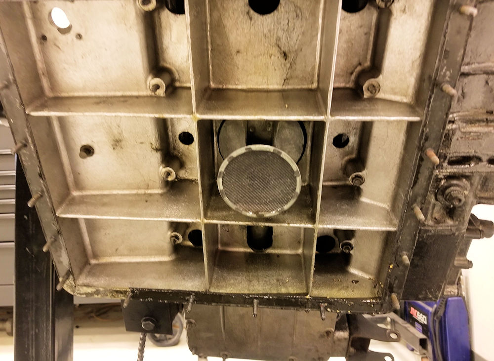
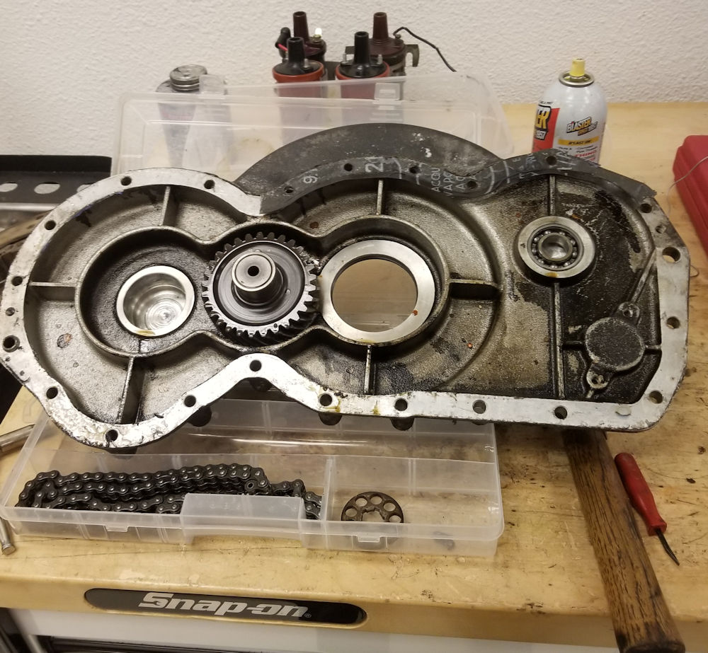
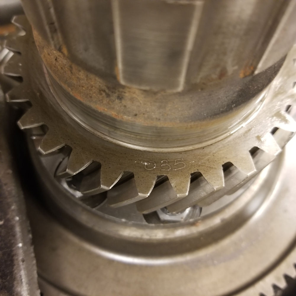
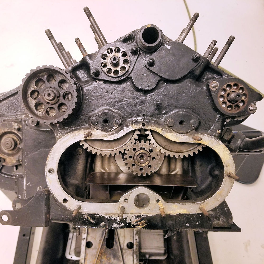
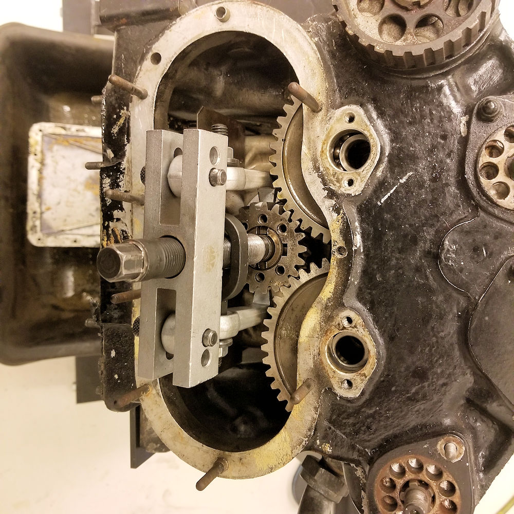
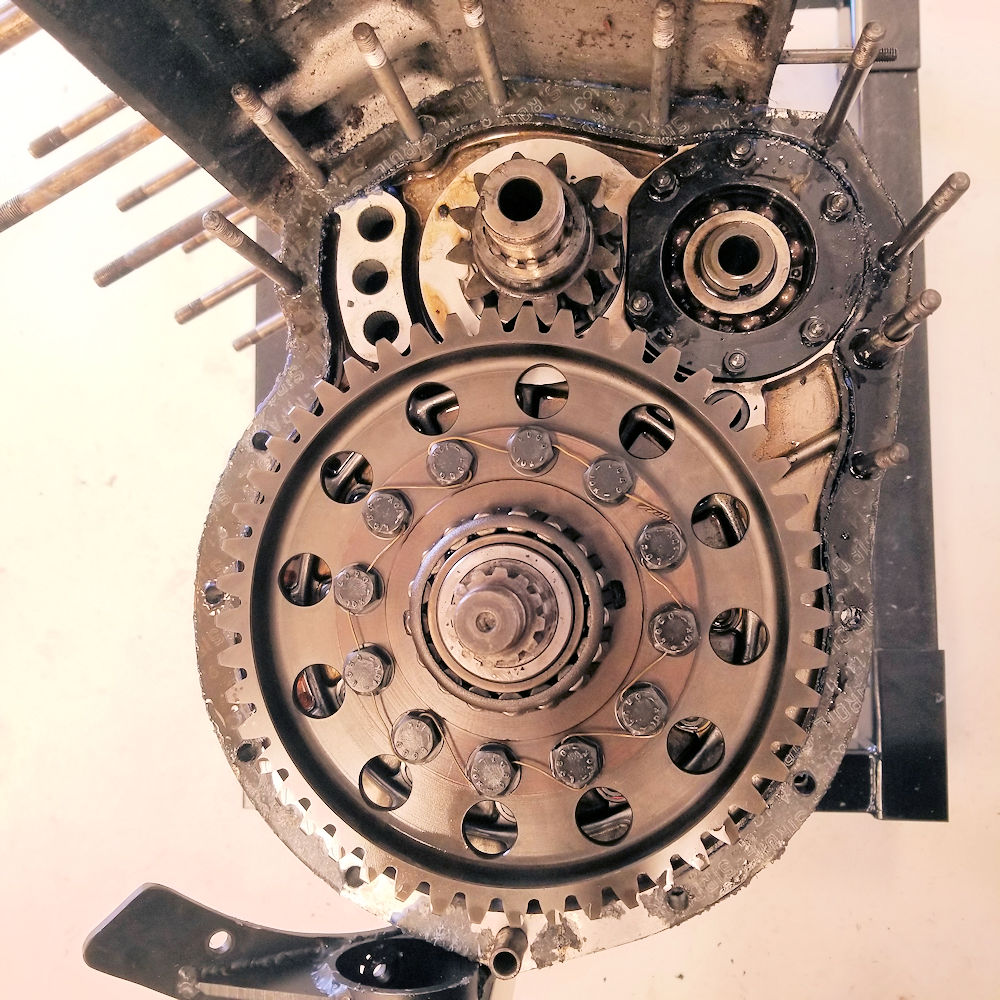
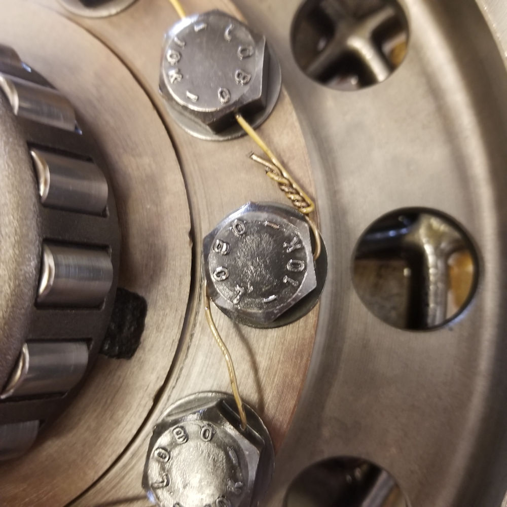
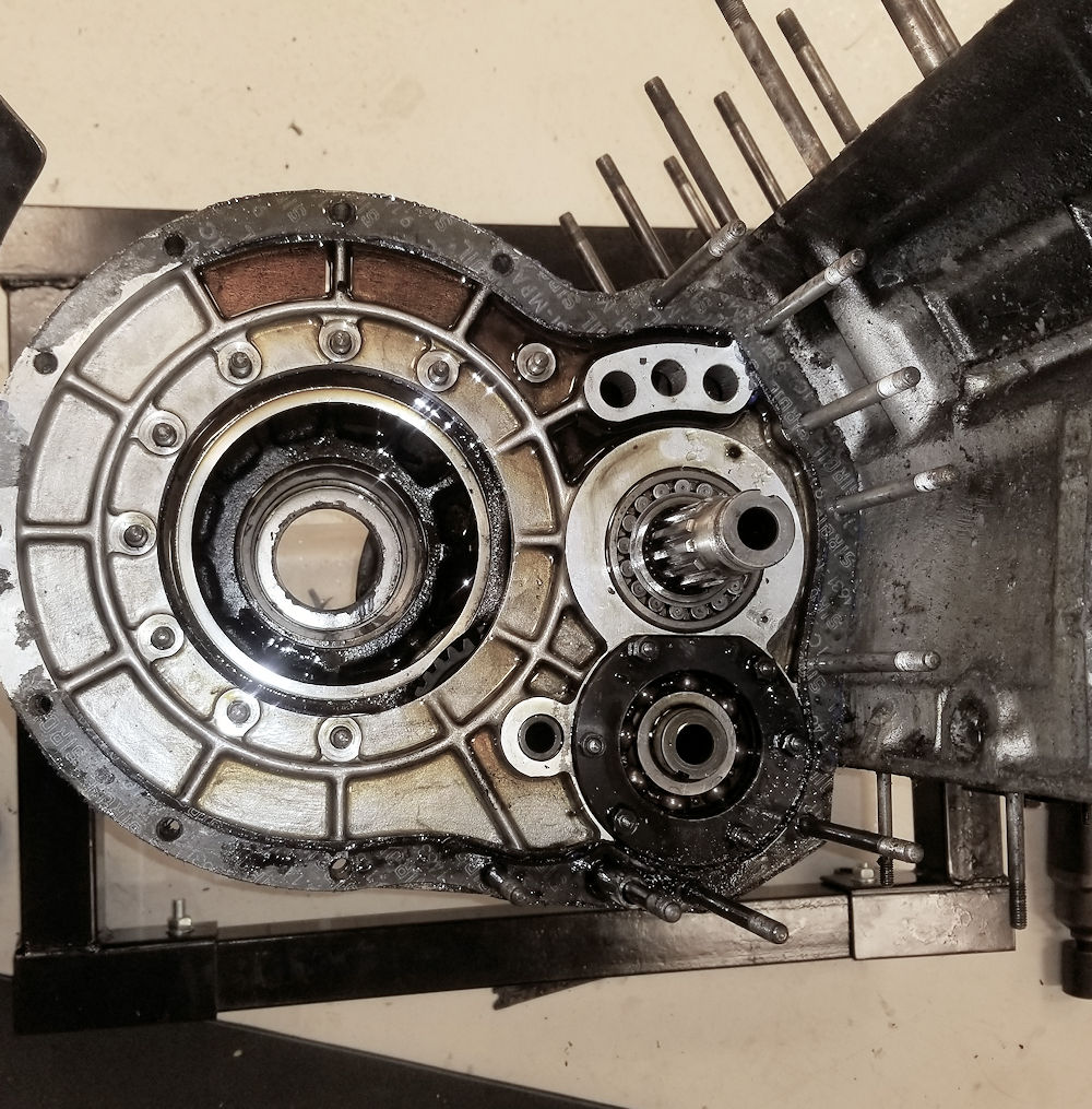
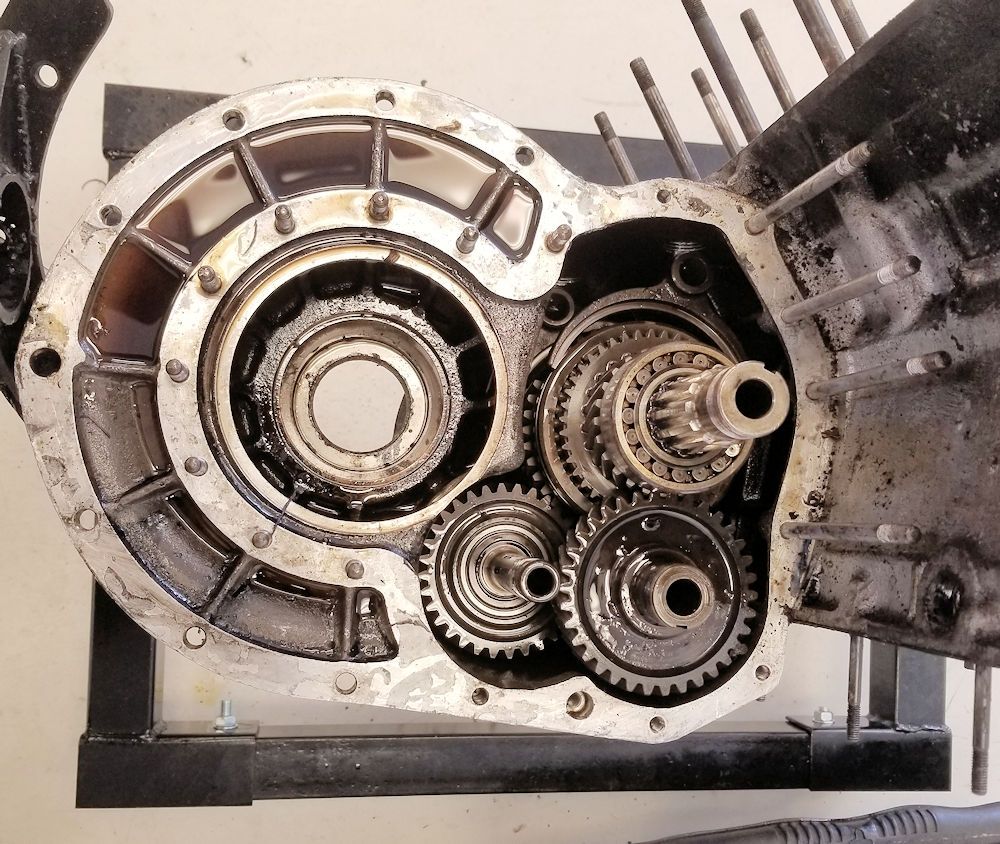
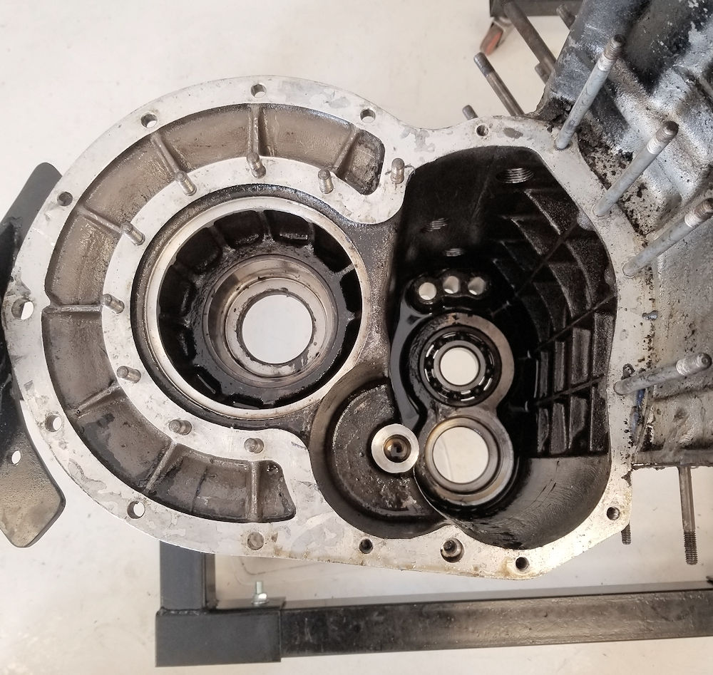
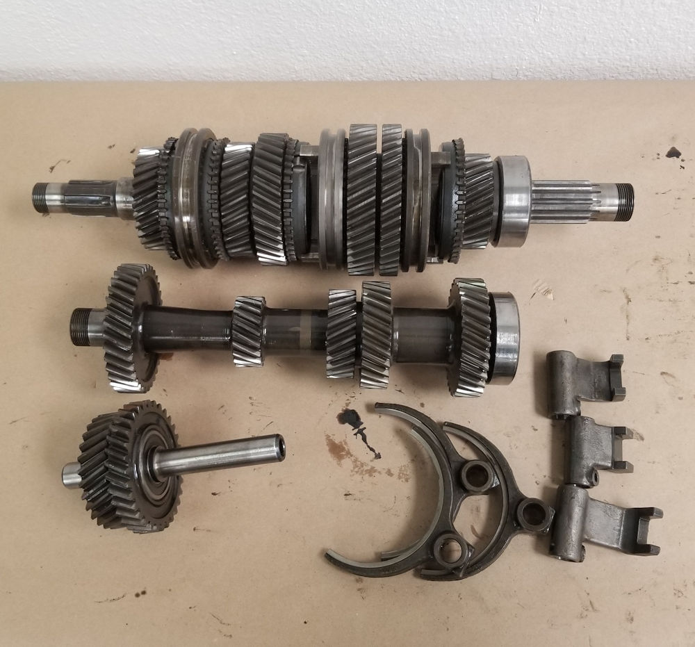
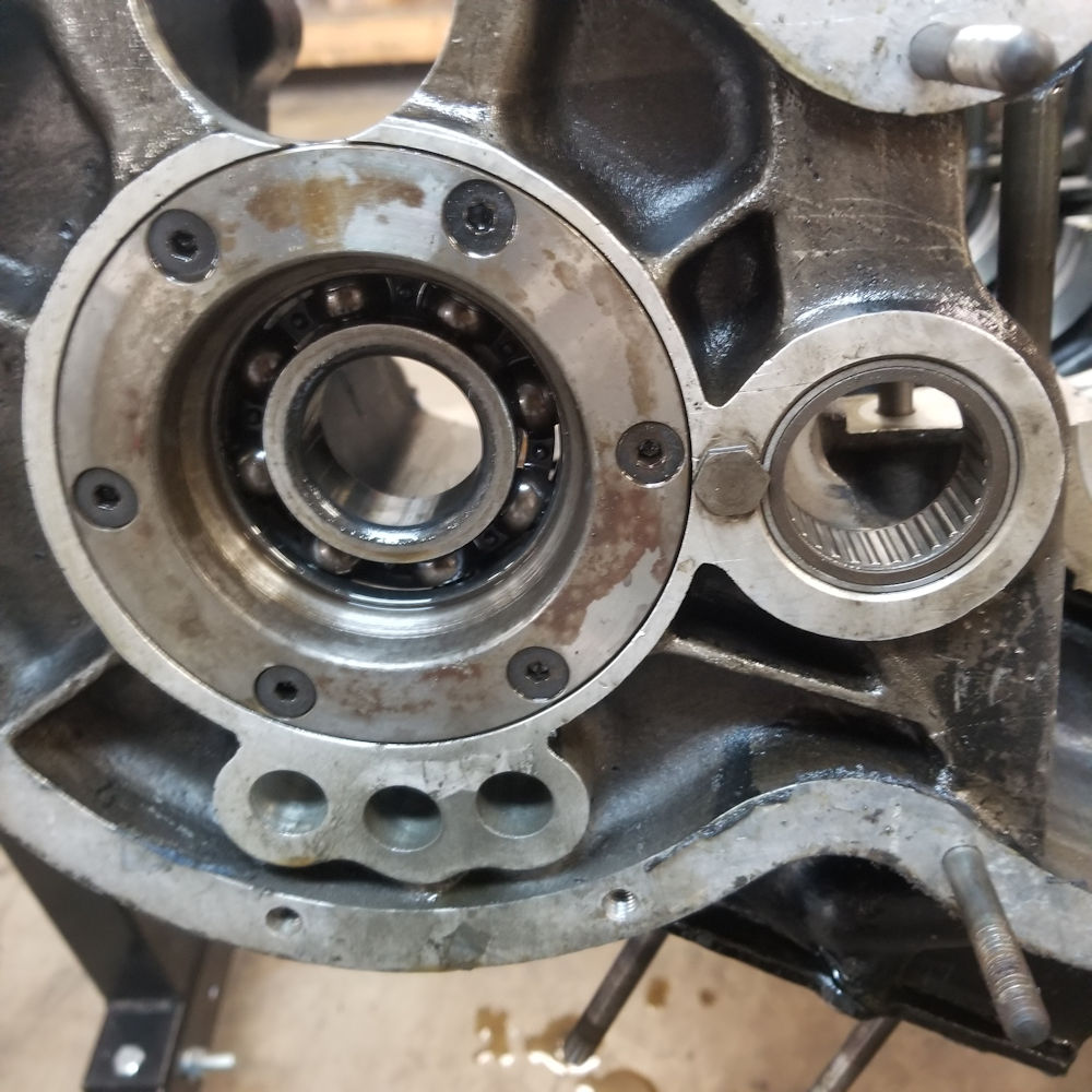
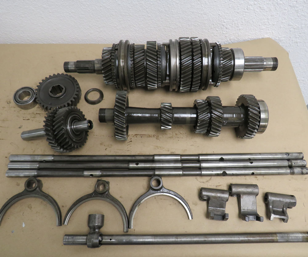
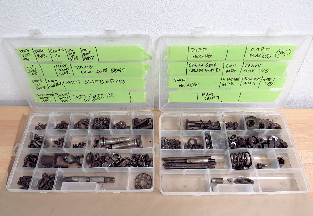
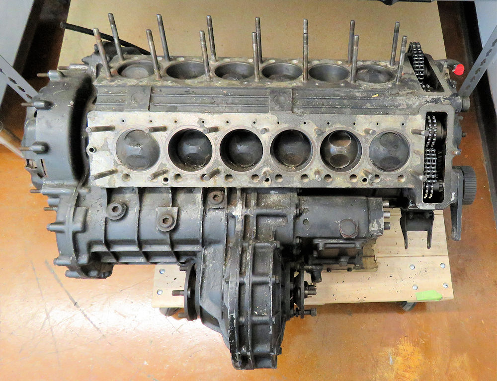
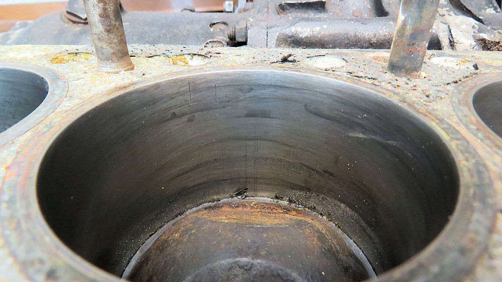
Earlier this week Josh disassembled
the short block and transaxle.
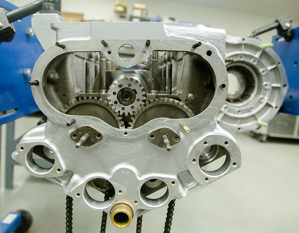
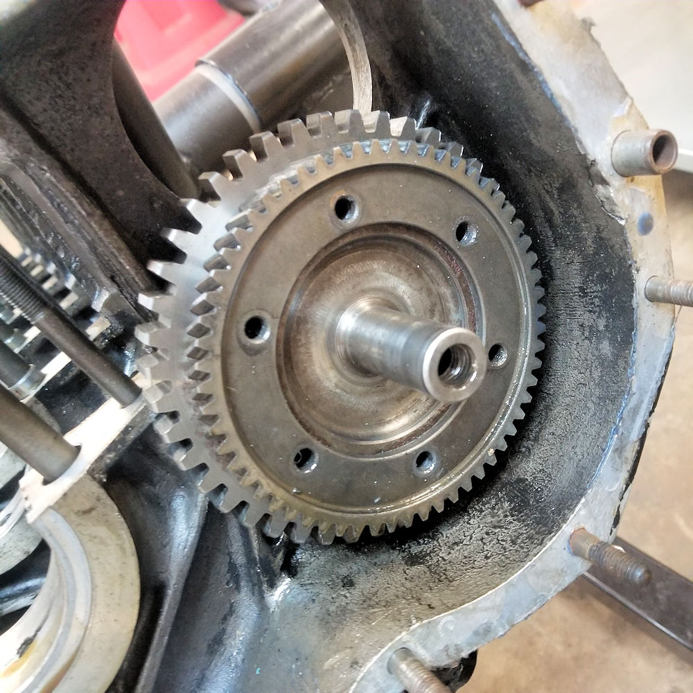
View inside the crankcase
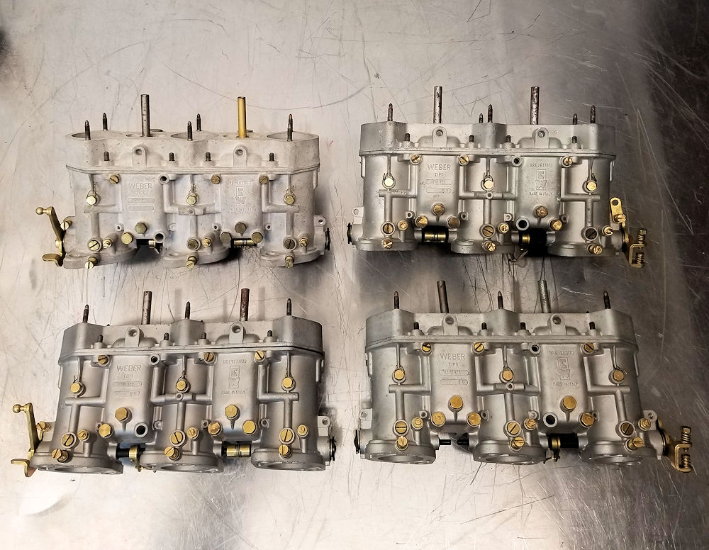
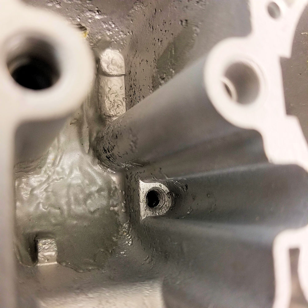
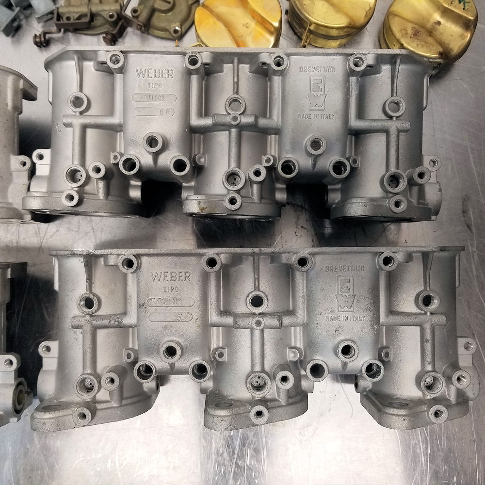
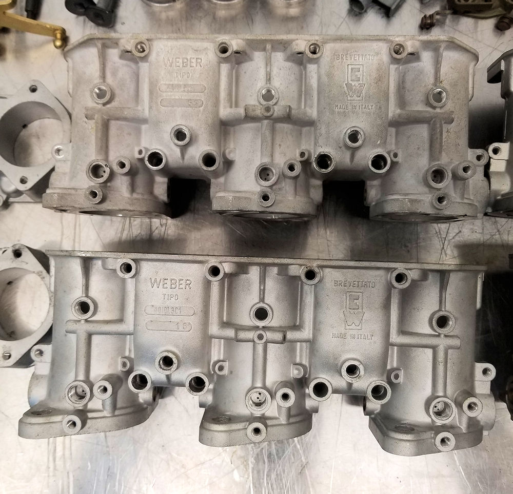
The
following sequence of photographs shows the disassembly
and inspection of the Weber carbs. We already knew that
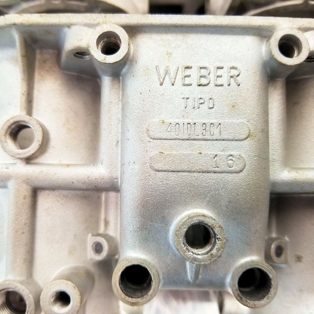
this car was one of the first Miuras ordered and built,
and the extremely low Weber serial numbers (16, 52, 59 and 88) mean these are almost
certainly the original carbs.
The Miura's carbs have been carefully stored
for
over 40 years
Carbs have suffered from corrosion and exhibit
significant pitting
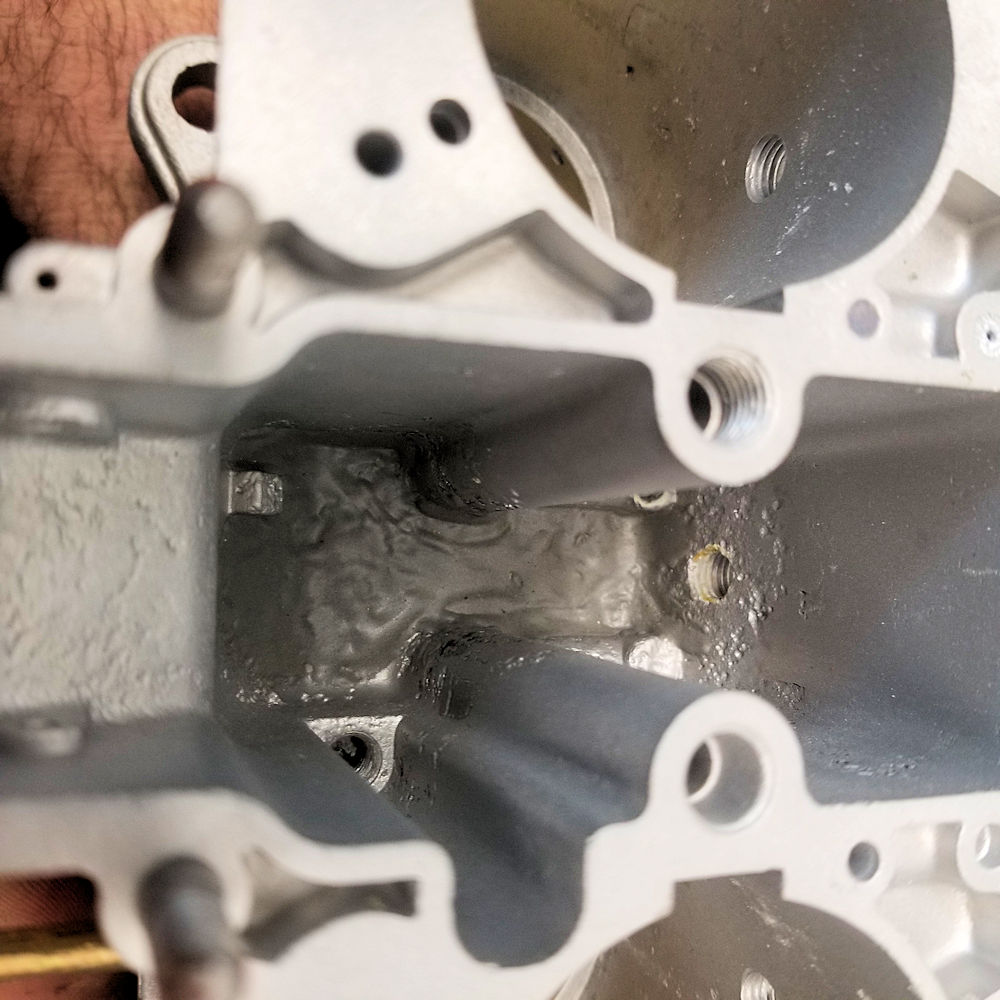
Previous epoxy repairs at the base of the fuel
bowls
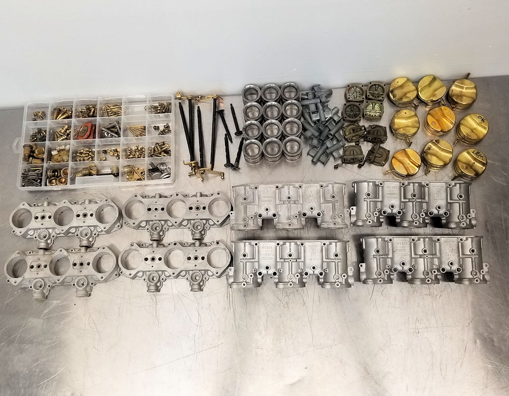
This is just the 16th Miura Weber carb made!
Carbs now fully torn down and inspected
All component parts carefully stored
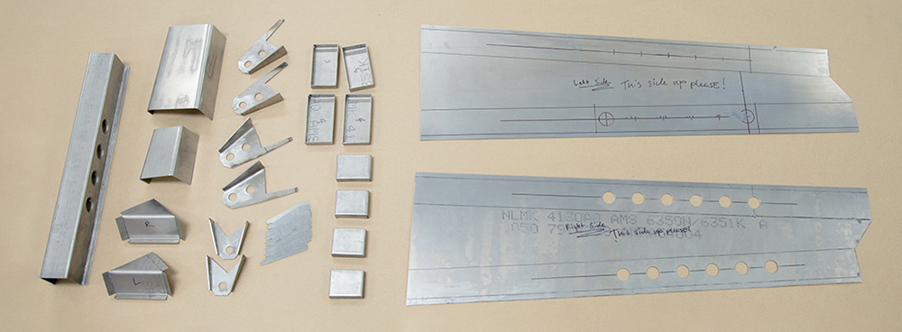
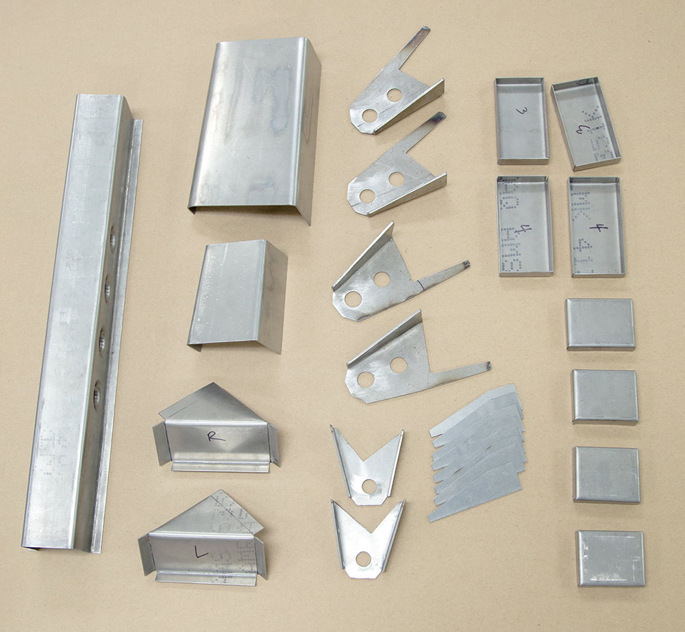
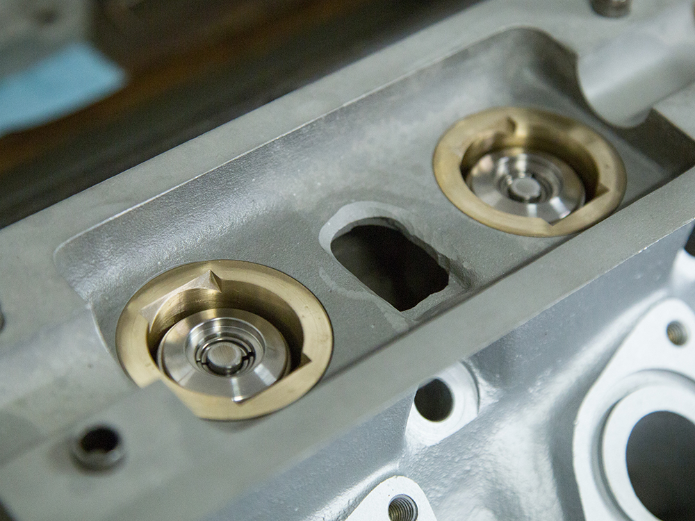
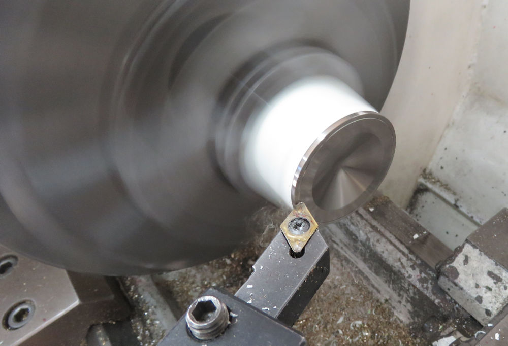
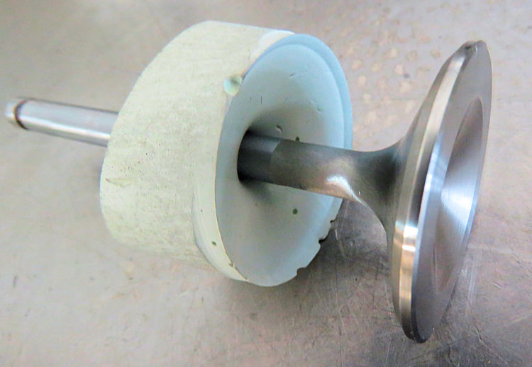
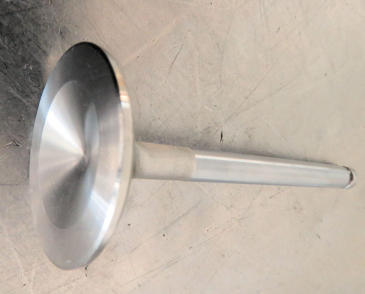
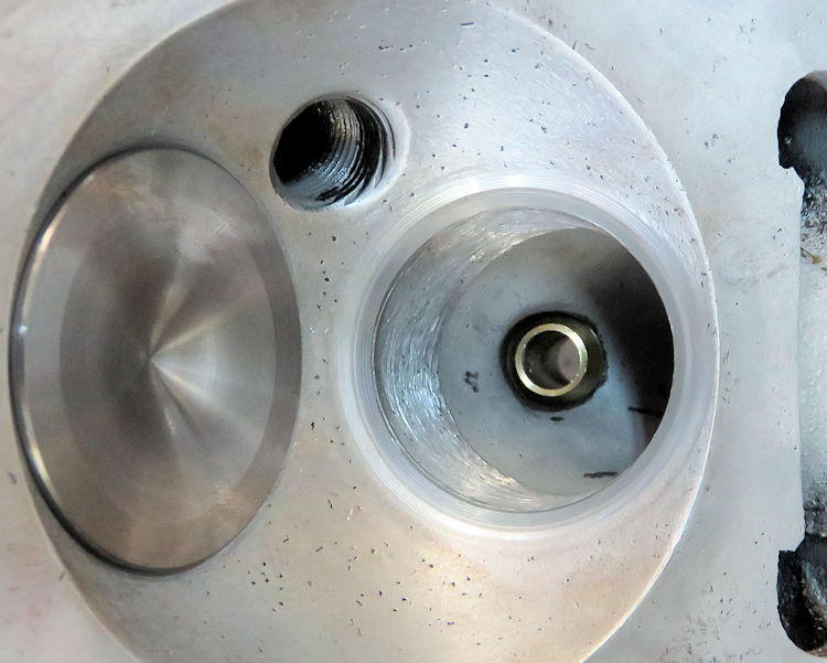
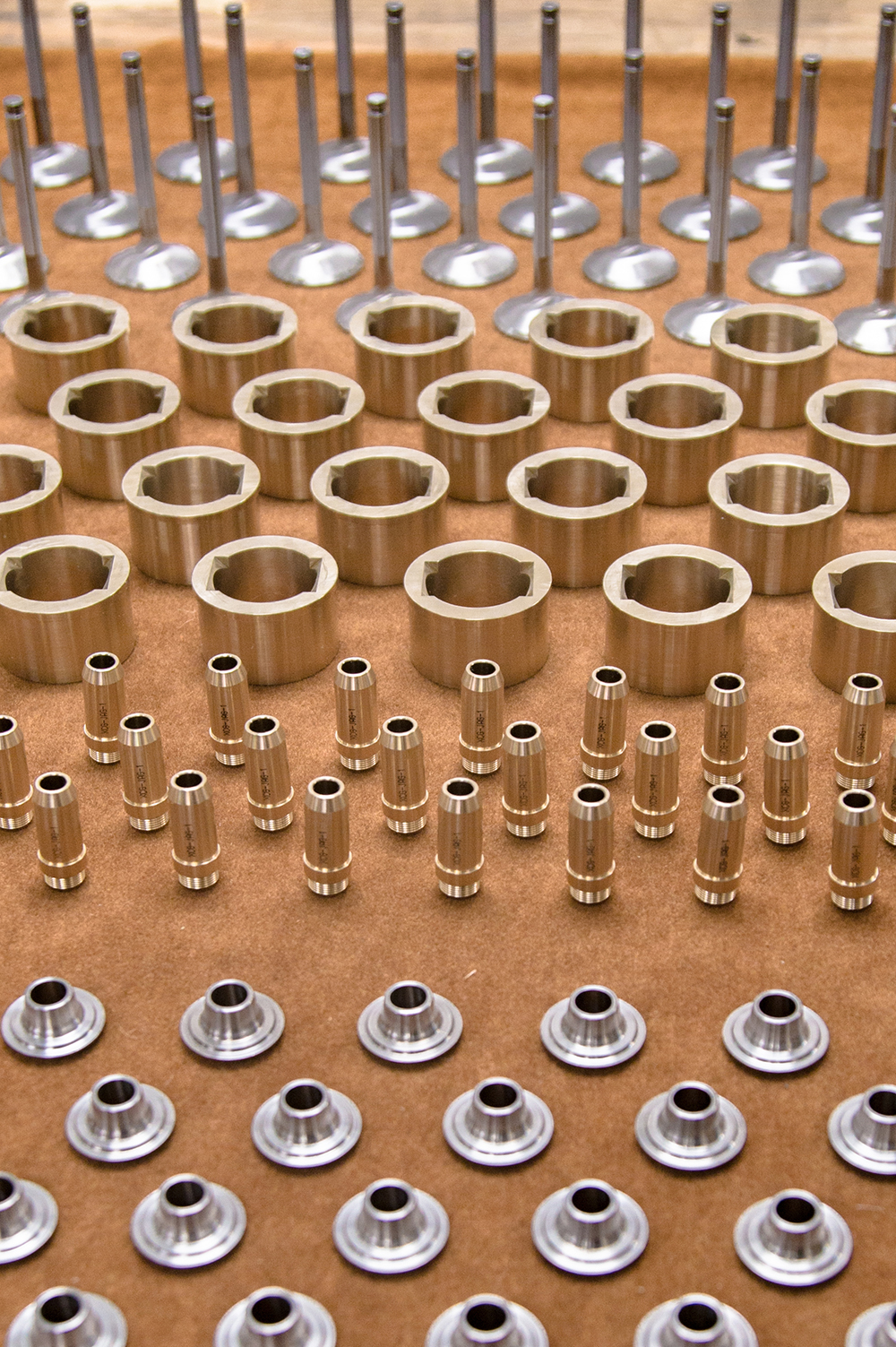
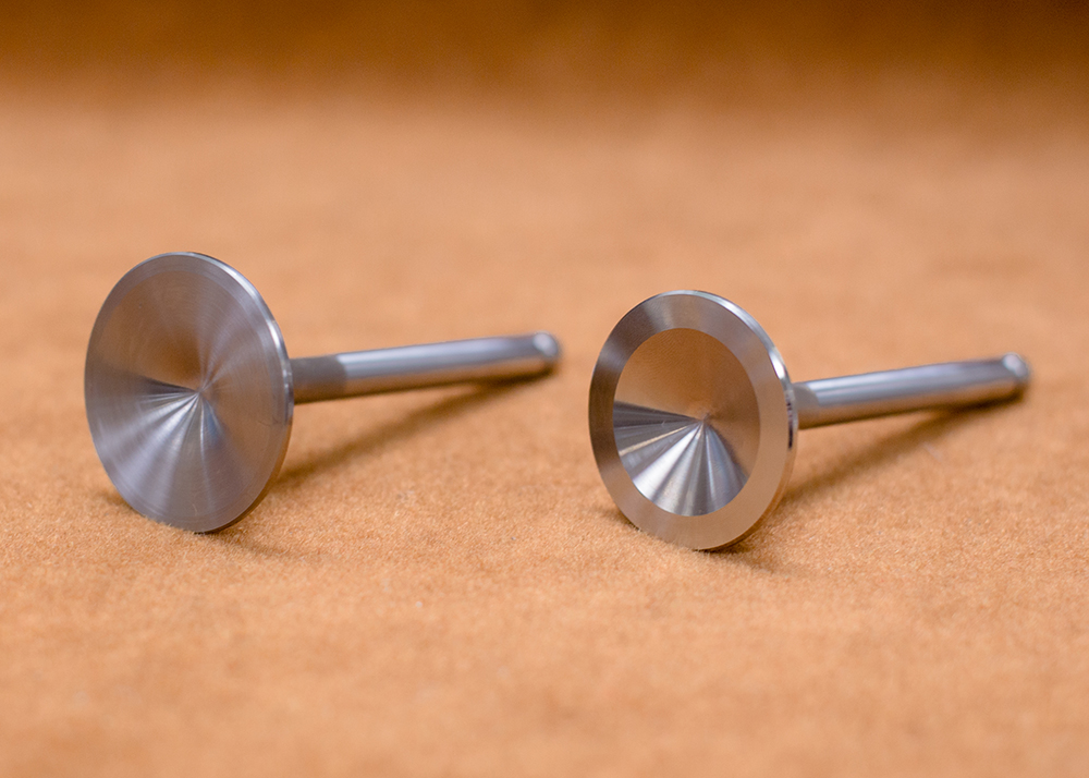
Corey has
been busy machining and trial fitting all the various
components for the valve train. He has machined custom
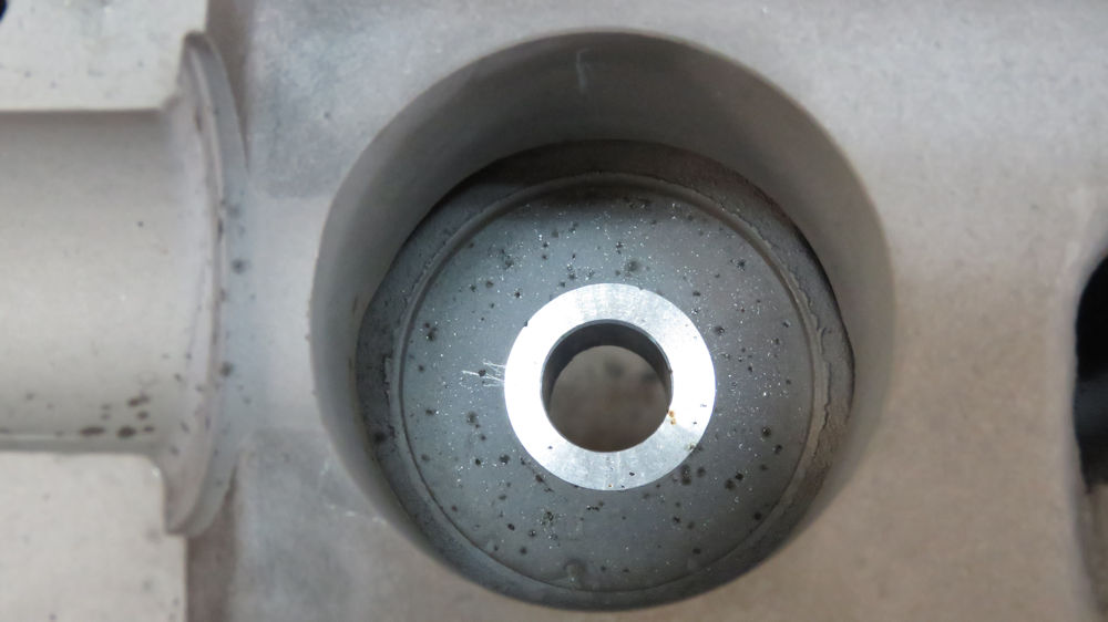
valve guides, tappet guides, valves and spring retainers.
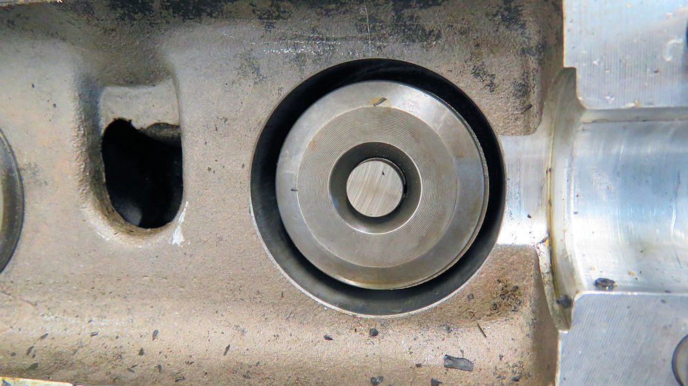
Machining the first valve guide
This protruding step inside the spring pocket
will
be removed
This modification is necessary because of the
upgrade to valve seals
Machining a mock-up valve
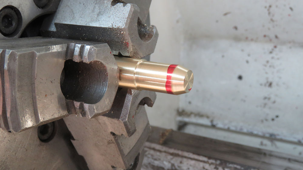
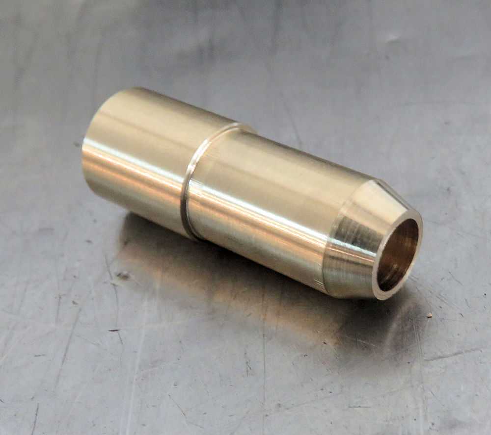
Machining a tappet guide from bearing bronze
stock
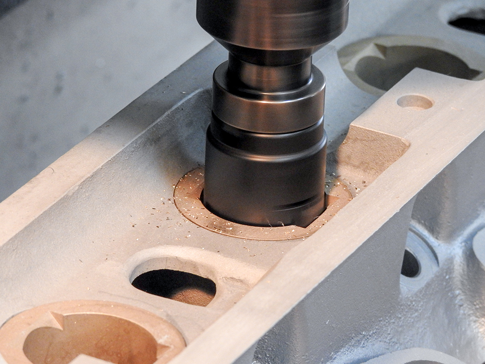
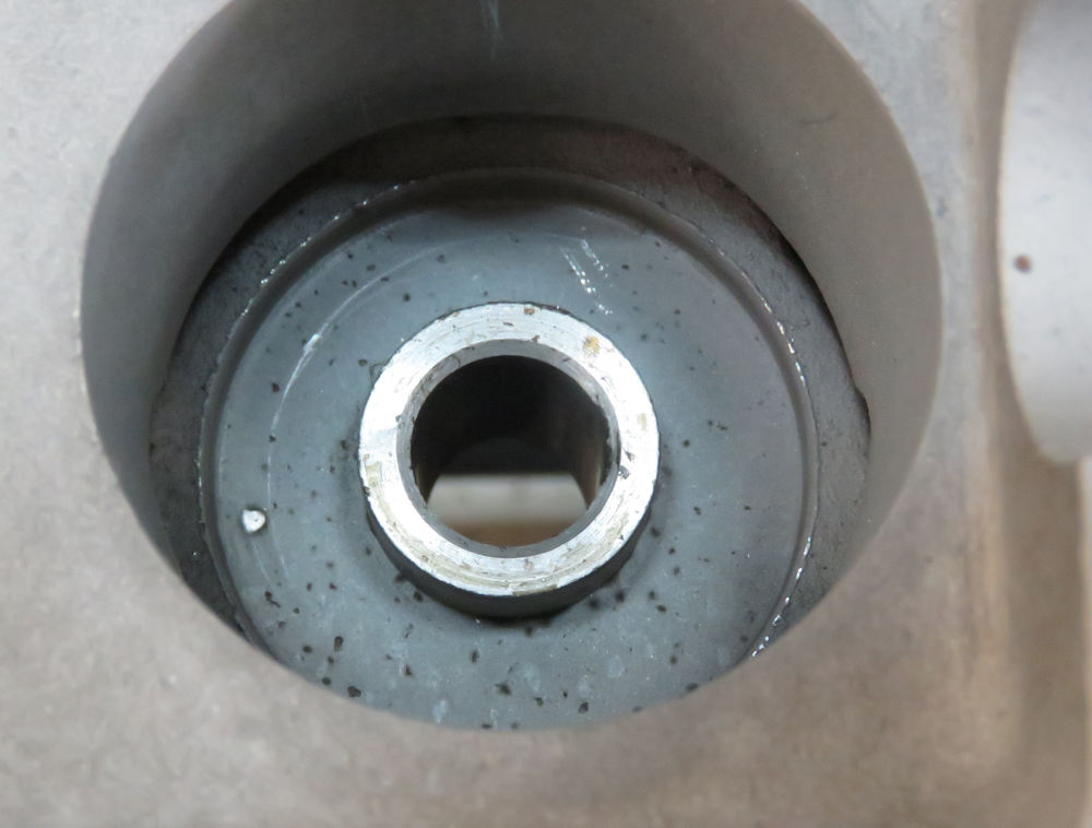
Head is counter bored to receive the tappet
guide
Tappet guide pressed into place
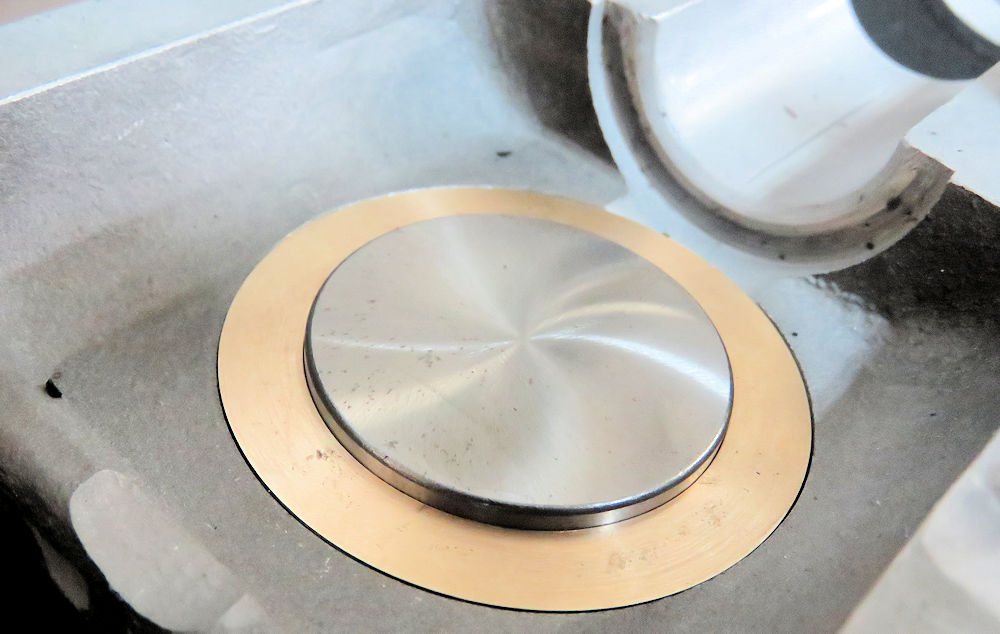
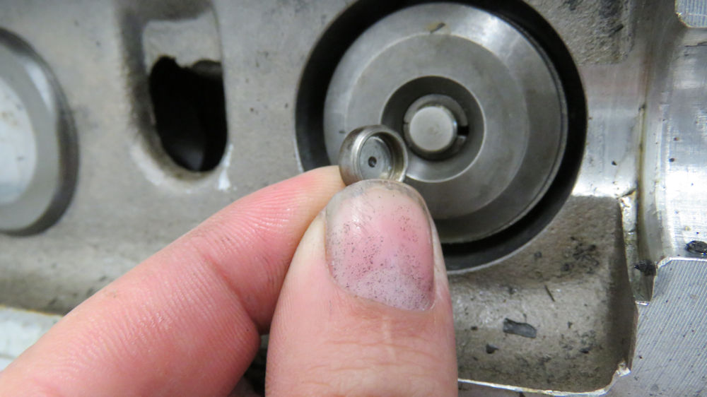
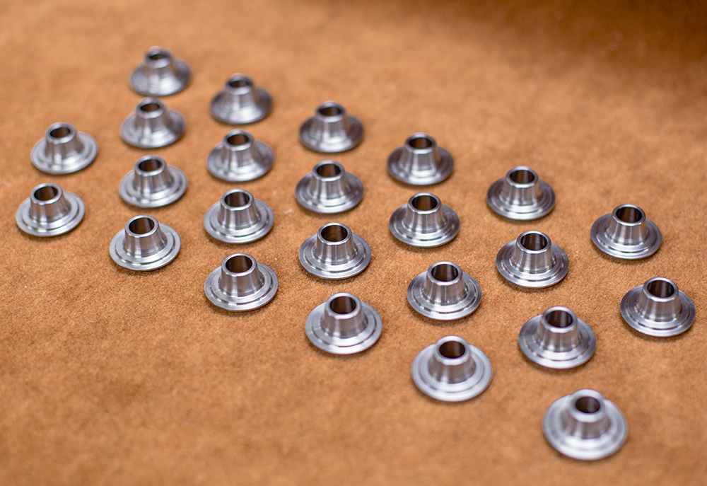
Mocking up the valve spring retainer
New retainer design allows the use of
shims to achieve desired valve lash
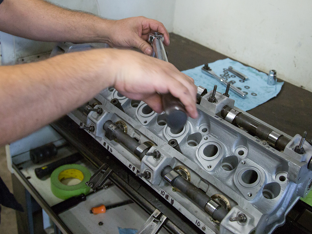
Trial fitting valve train
Smaller, lightweight tappet in place inside
tappet guide
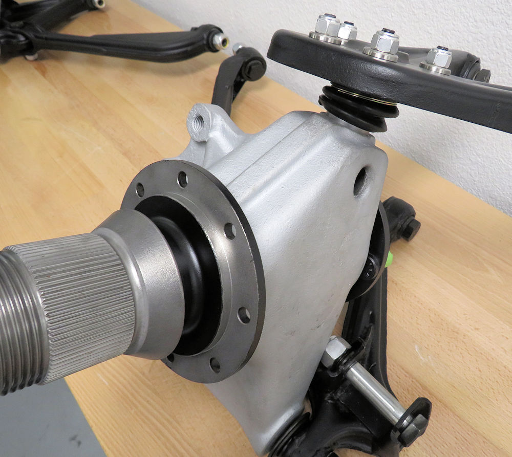
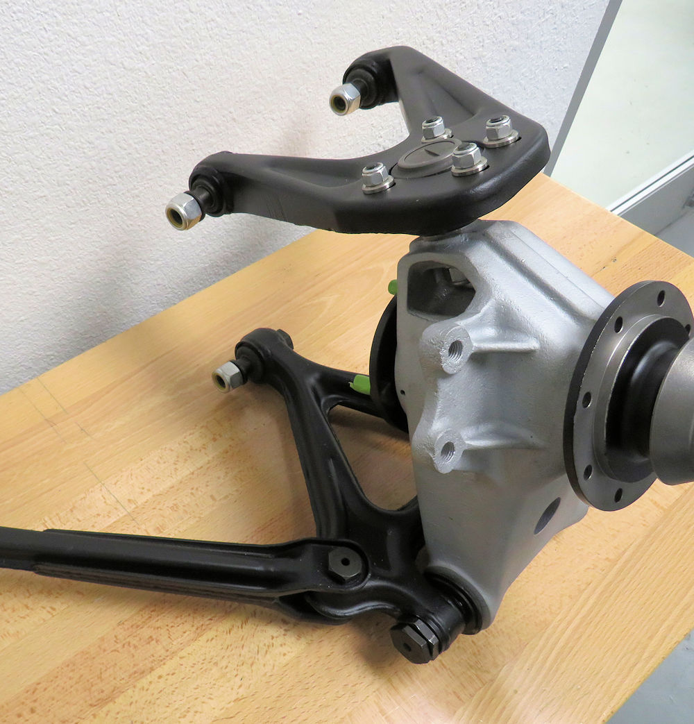
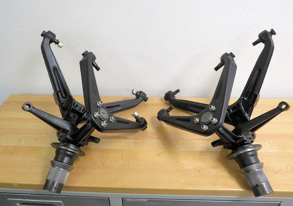
Front and
rear suspension has now been restored, rebuilt and loosely
assembled.
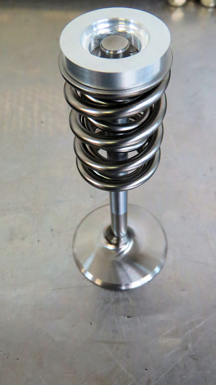
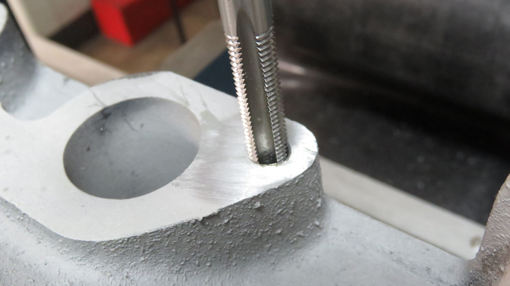
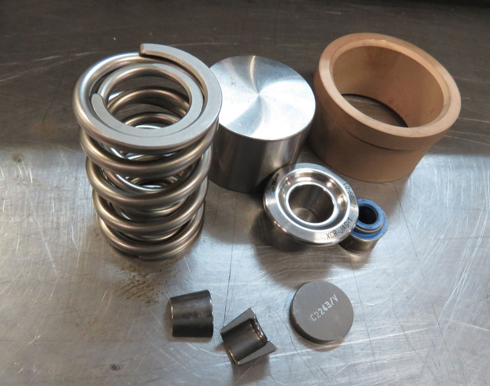
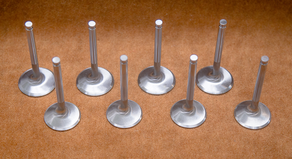
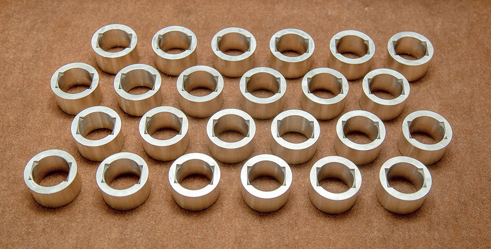
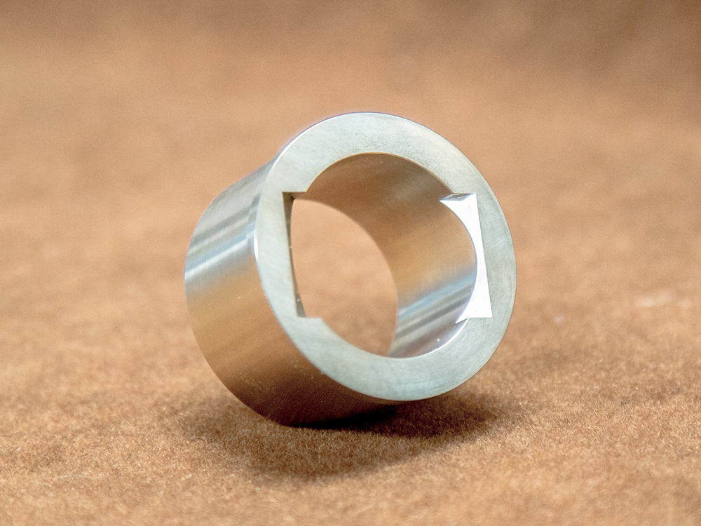
The first six
photos below show Corey dealing with a broken and seized
stud. The next photos in the sequence demonstrate how we are
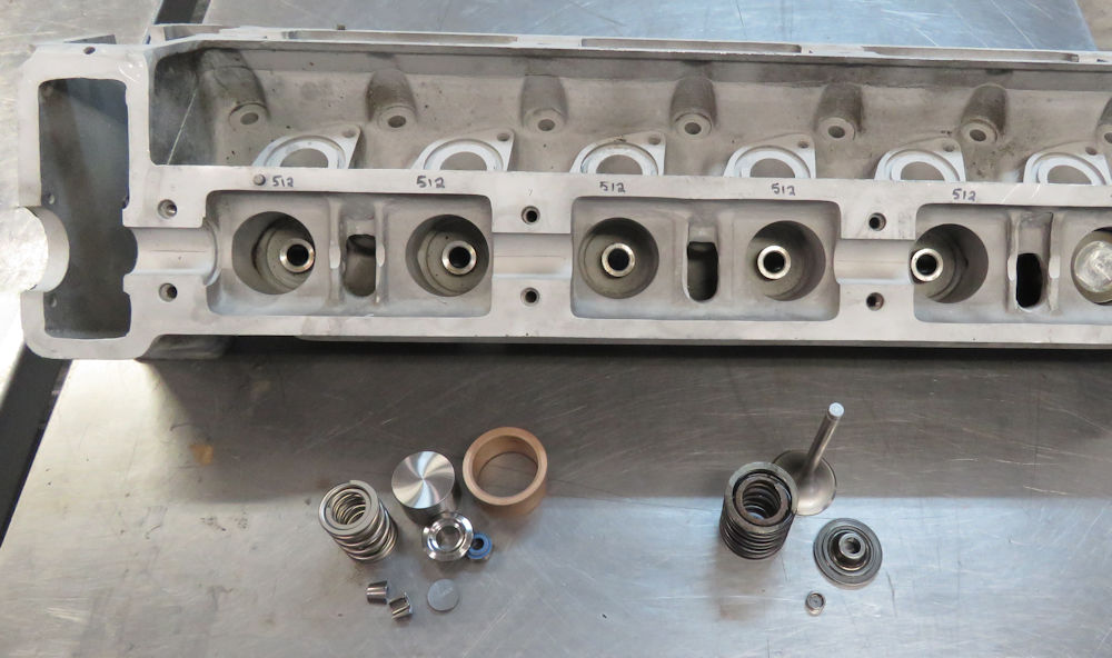
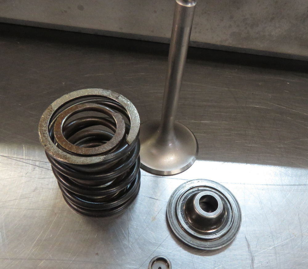
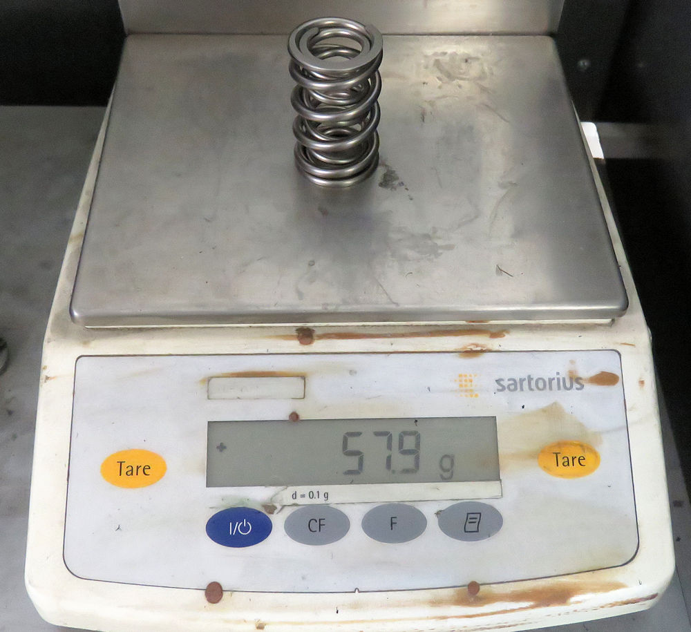
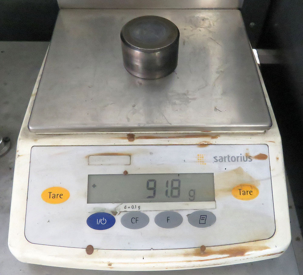
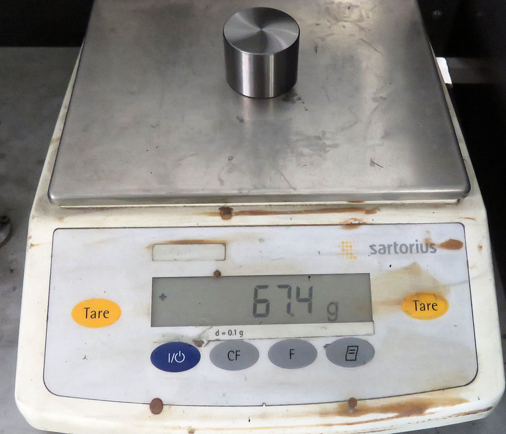
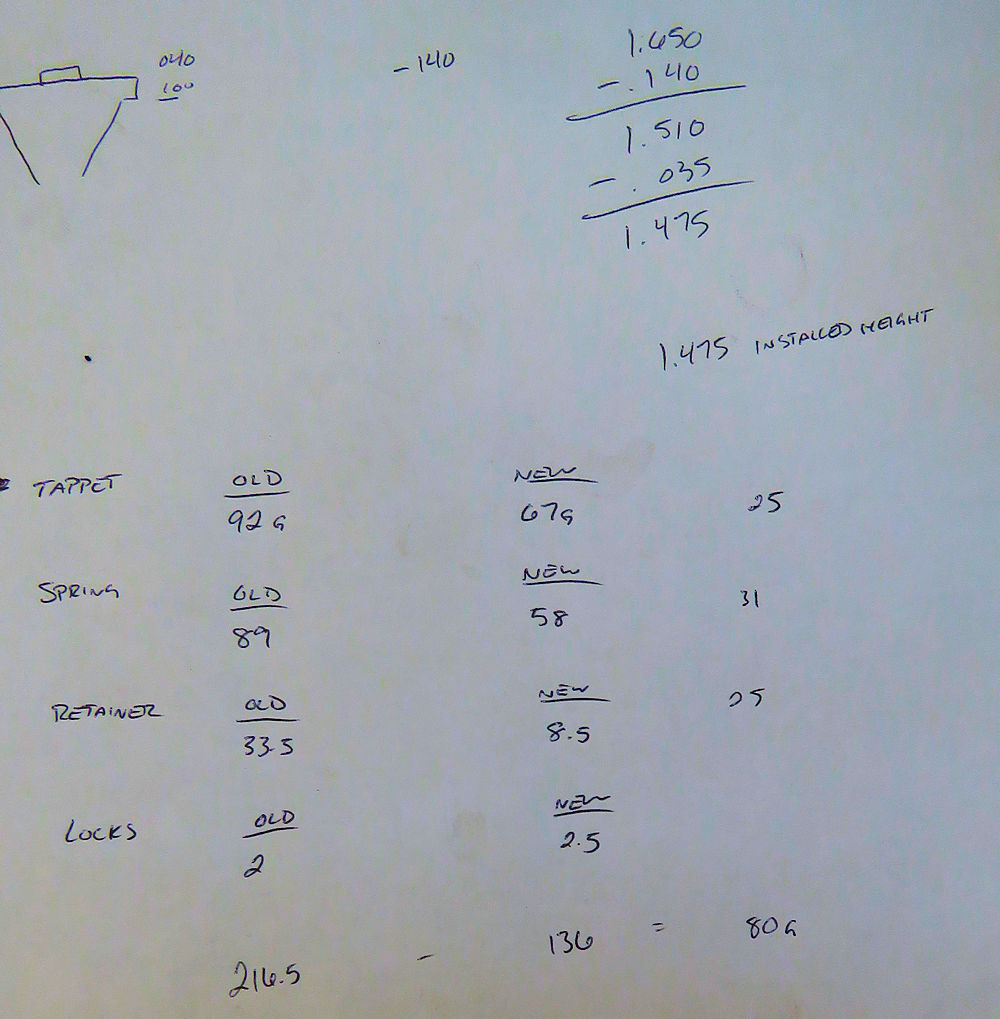
going to put the valve assemblies on a strict diet!
The original tappet buckets are unnecessarily large and
heavy, and they ride inside aluminum tappet bores that have
been damaged due to contact with the steel tappets. The
springs are also unnecessarily oversized and heavy, which in
turn means the spring retainers are also on the portly side!
During the rebuild we will be using smaller, much lighter
components in the valve train, and also press fitting new
tappet bores. The new custom spring retainers will allow us
to use a more effective shim system to set and adjust valve
lash, and we also be using custom guides that will allow us
to retrofit valve seals throughout. Even before we have
compared the weight of the old valves versus the custom
valves we are having made, we are seeing a weight saving of
80g per valve assembly, meaning 1,920g across all 24 valves.
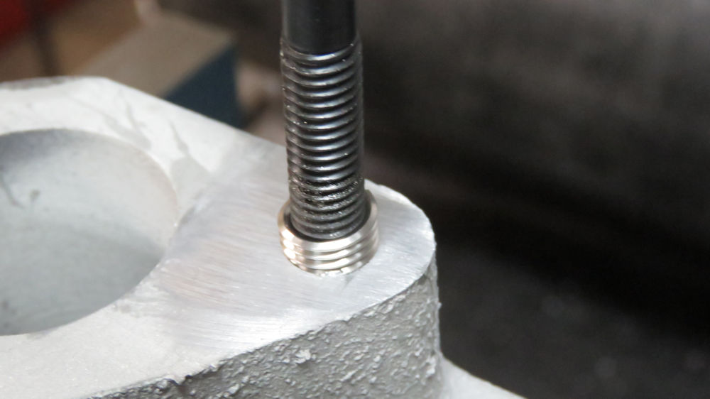
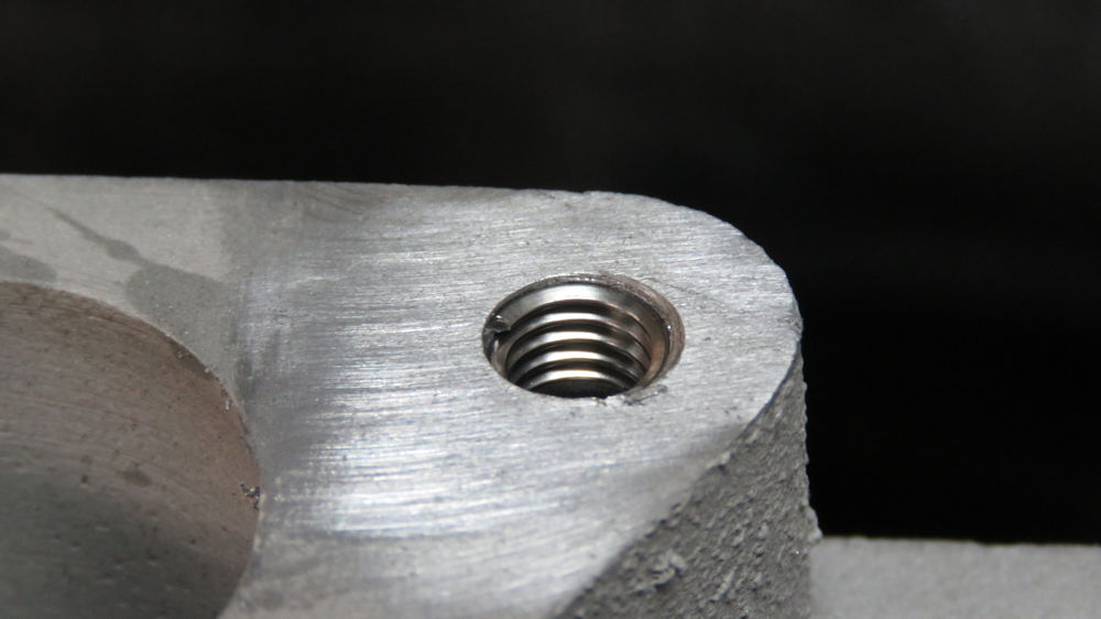
Broken and seized stud
Installing the new threaded insert
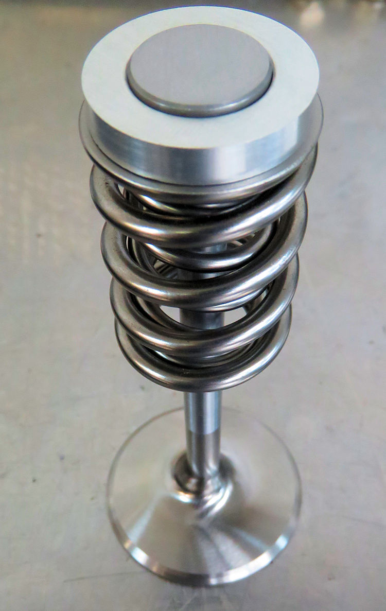
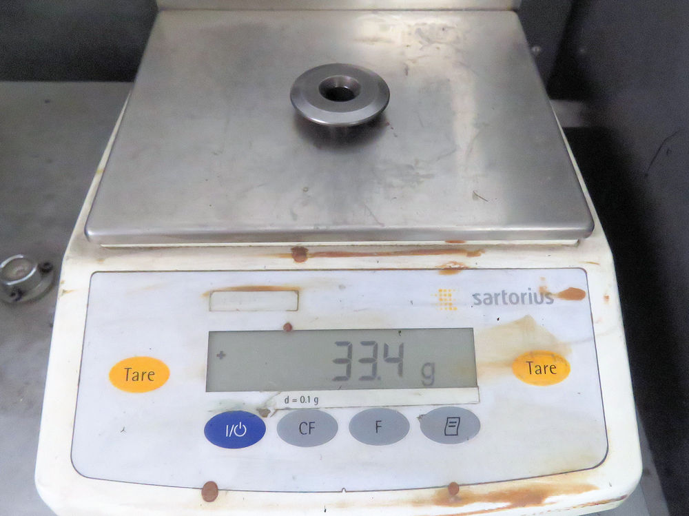
Putting the valve train on a strict weight
loss program
Original tappets, springs and retainers are
all
unnecessarily heavy
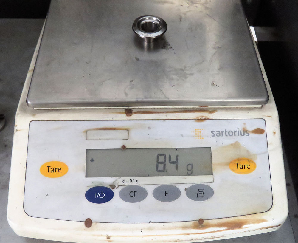
Original spring retainer
Custom TCJ retainer
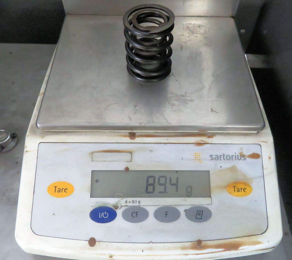
Original valve springs
Custom TCJ valve springs
Original tappet
Custom TCJ tappet
80g weight saving per valve assembly
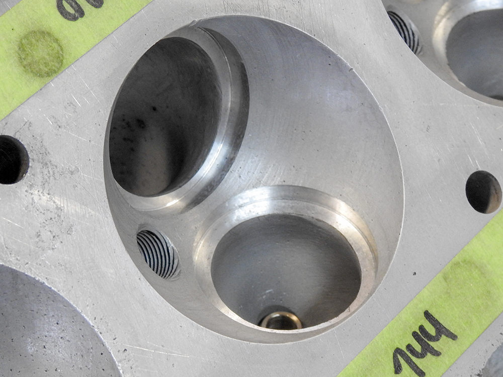
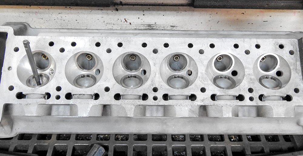
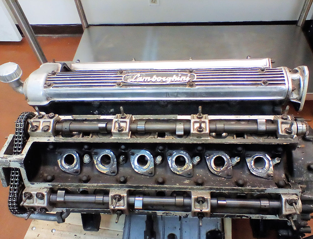
Disassembly and
inspection of the cylinder heads.
Removing the large and very
heavy tappets
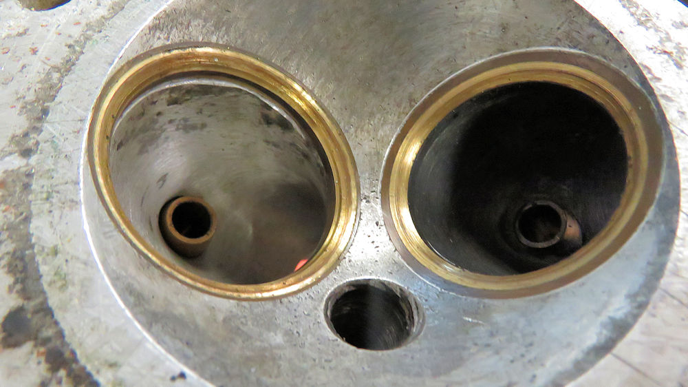
Original bronze seats and a scary looking
valve job!
Overall cylinder head castings are in
excellent
condition with no serious corrosion evident
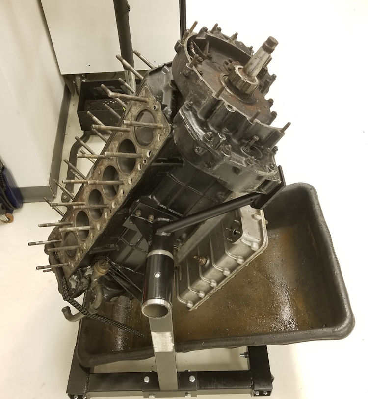
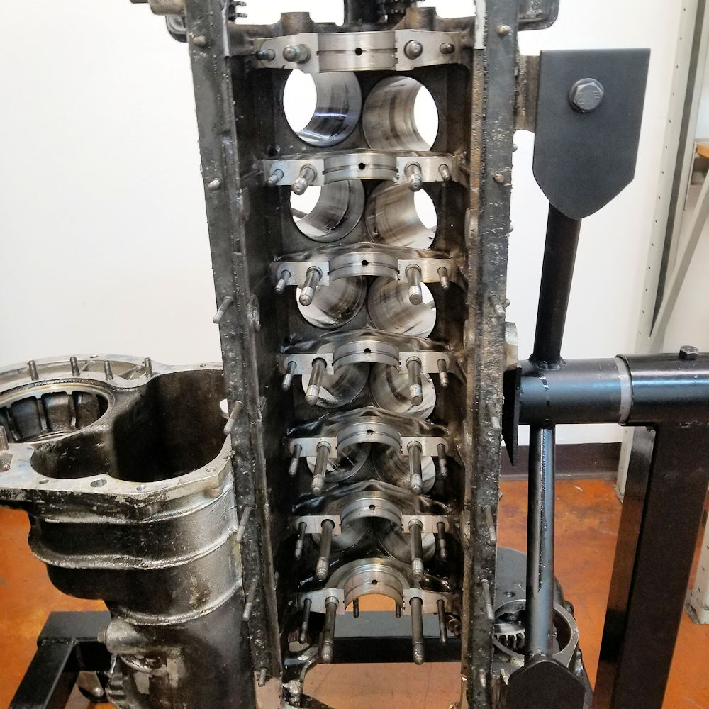
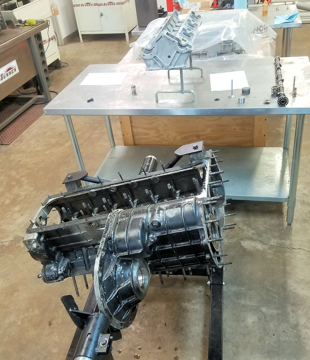
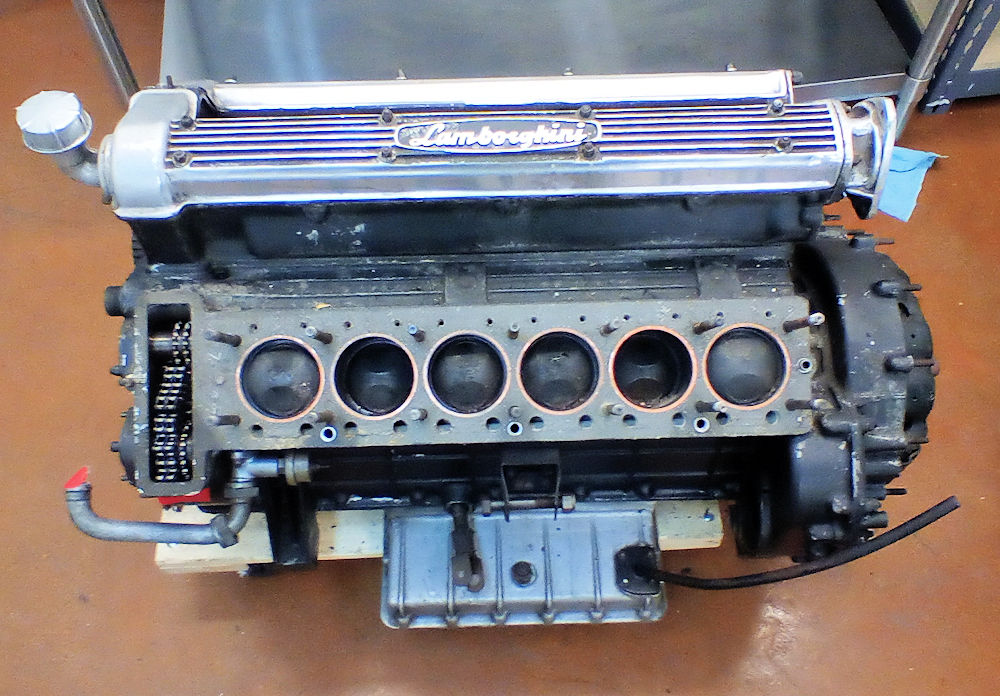
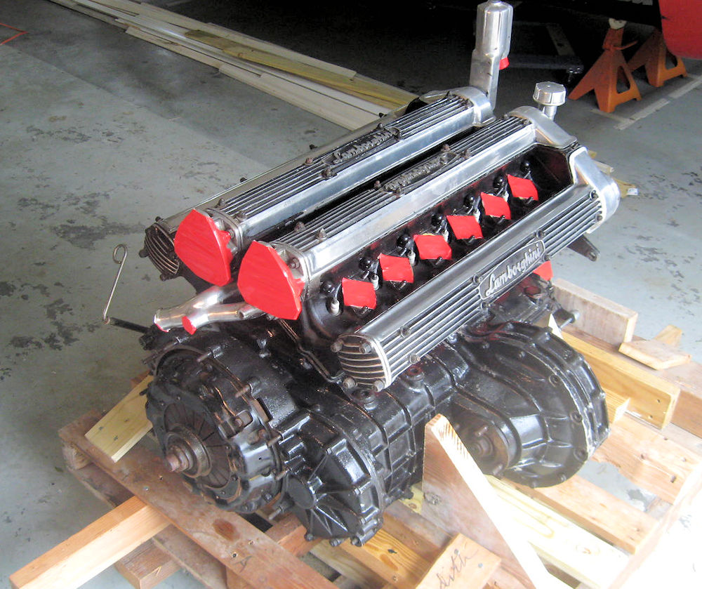
Time to get the
engine and transaxle rebuilds underway!
Although we understand this engine had a partial rebuild
performed many years ago, it has not been run since and is
actually seized at this time. Having removed the cylinder
heads, it looks as if the heads have been serviced but the
bottom end does not appear to have been rebuilt. Although we
have yet to tear down the short block, it appears that the
original Borgo pistons are still installed. More on this as the disassembly
progresses.
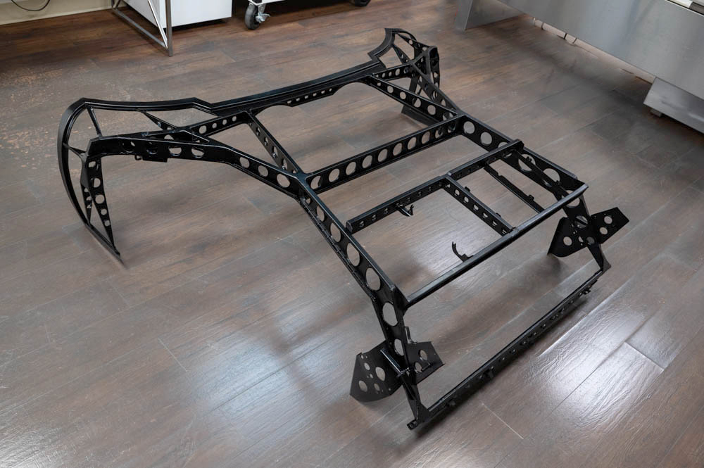
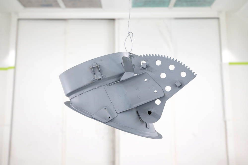
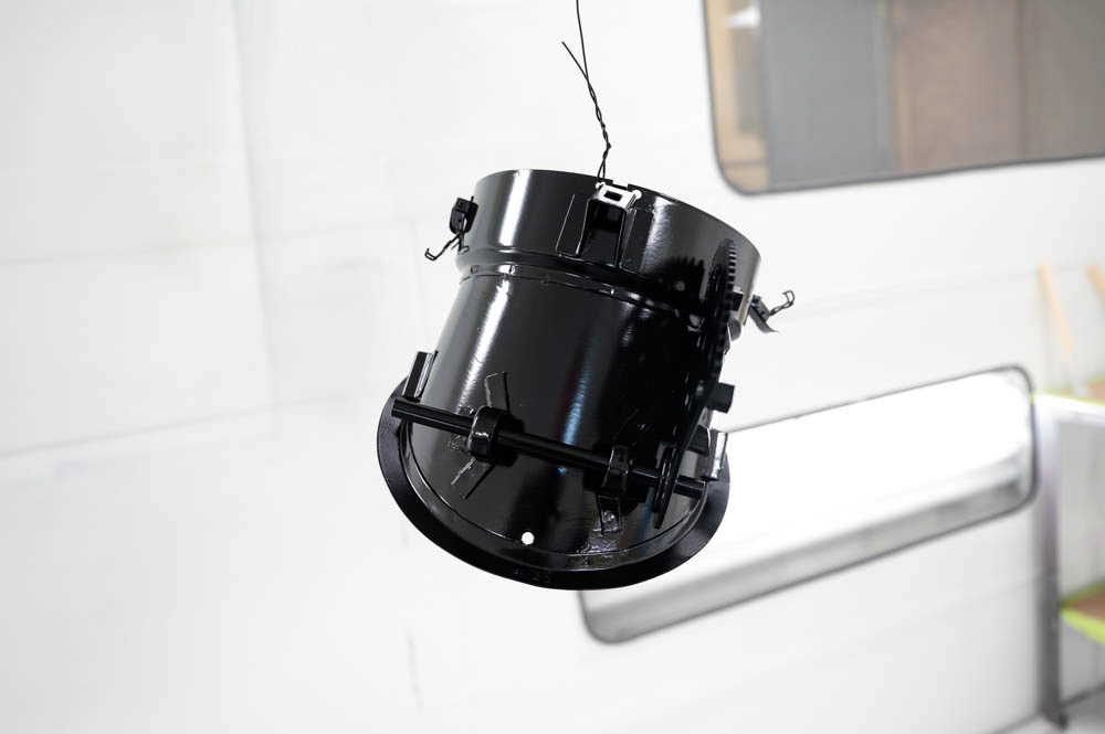
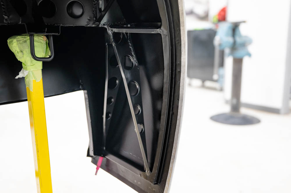
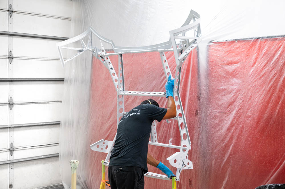
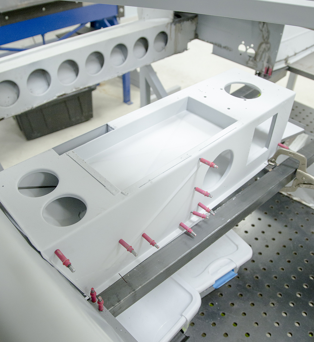
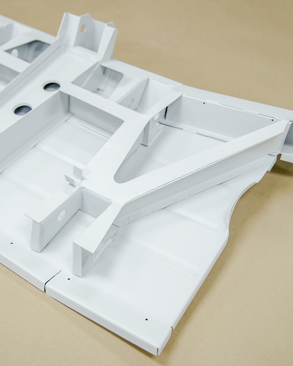
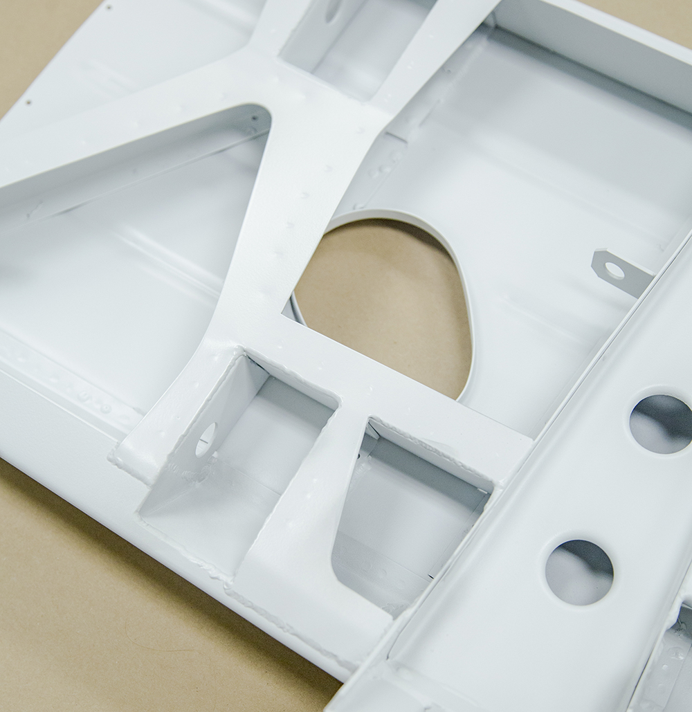
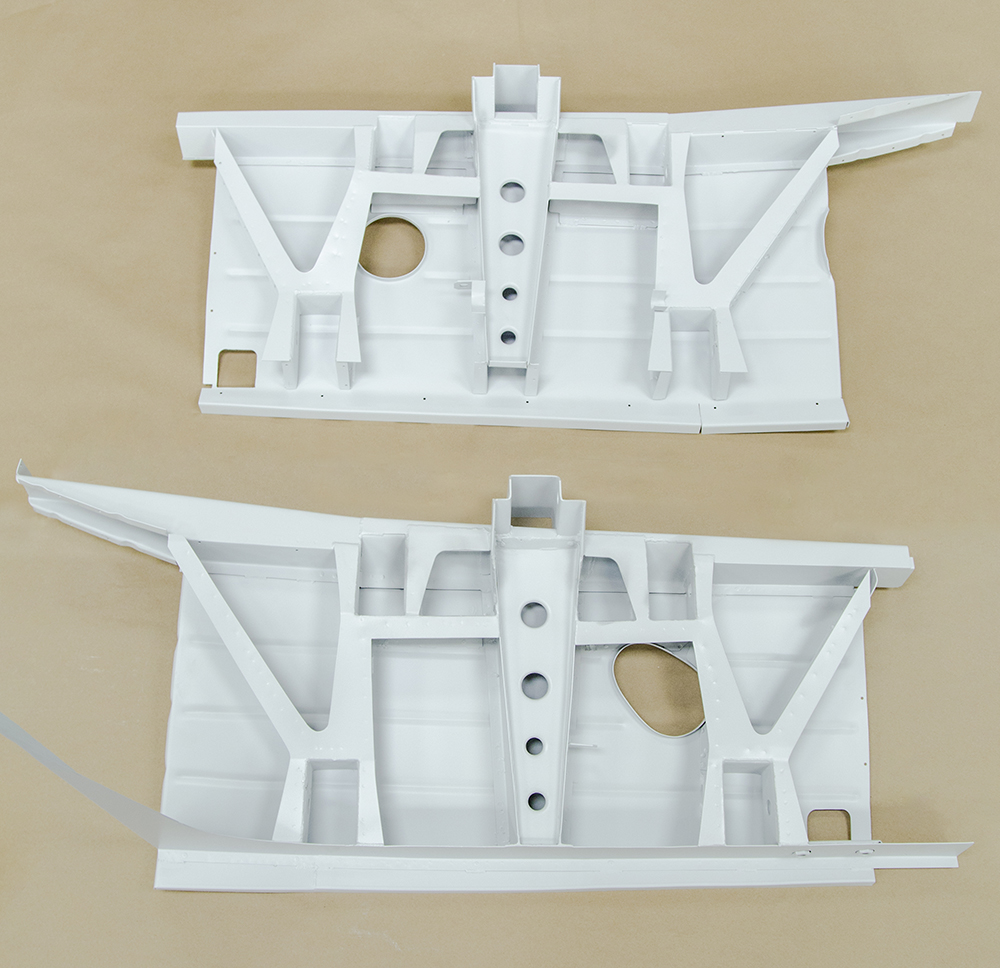
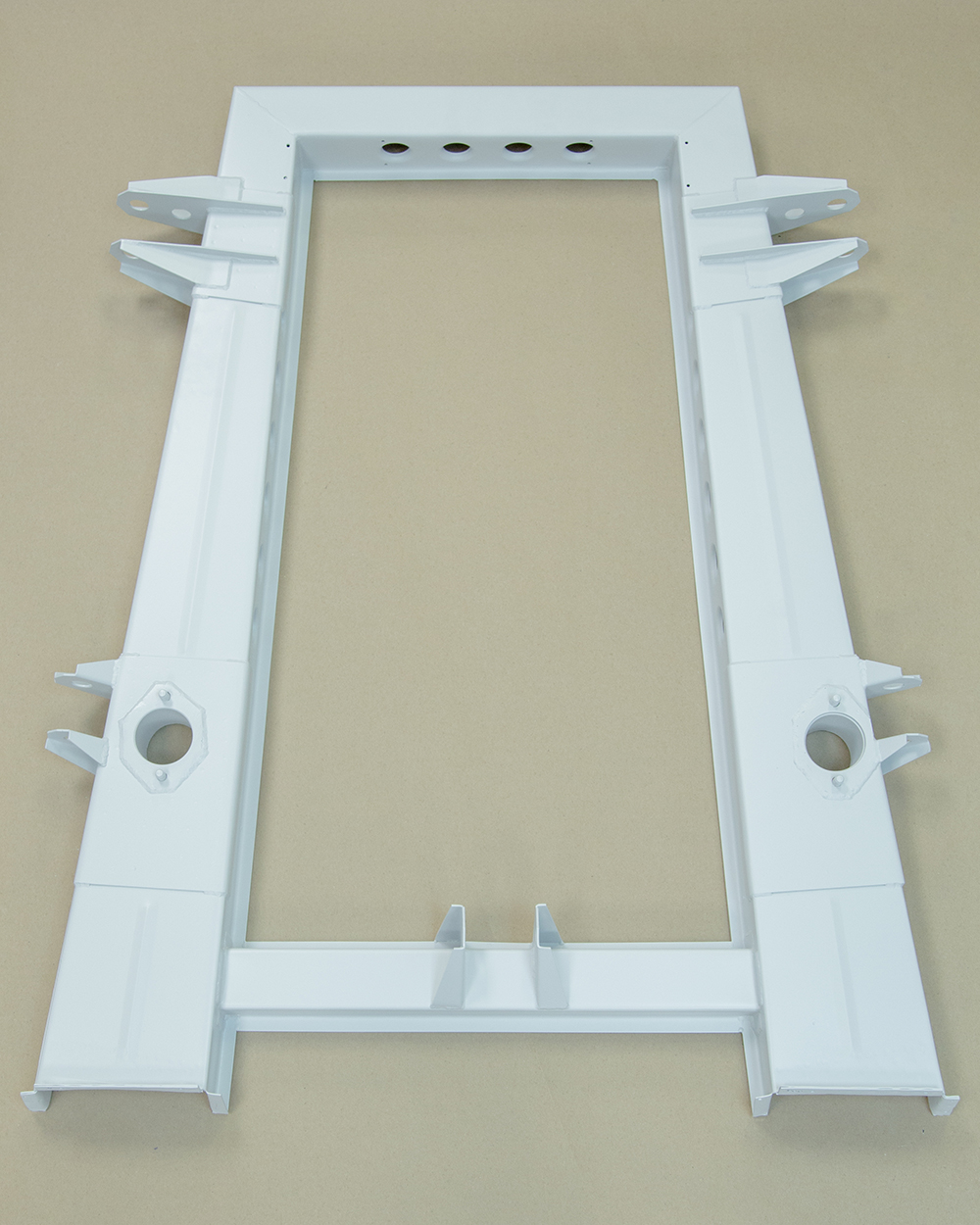
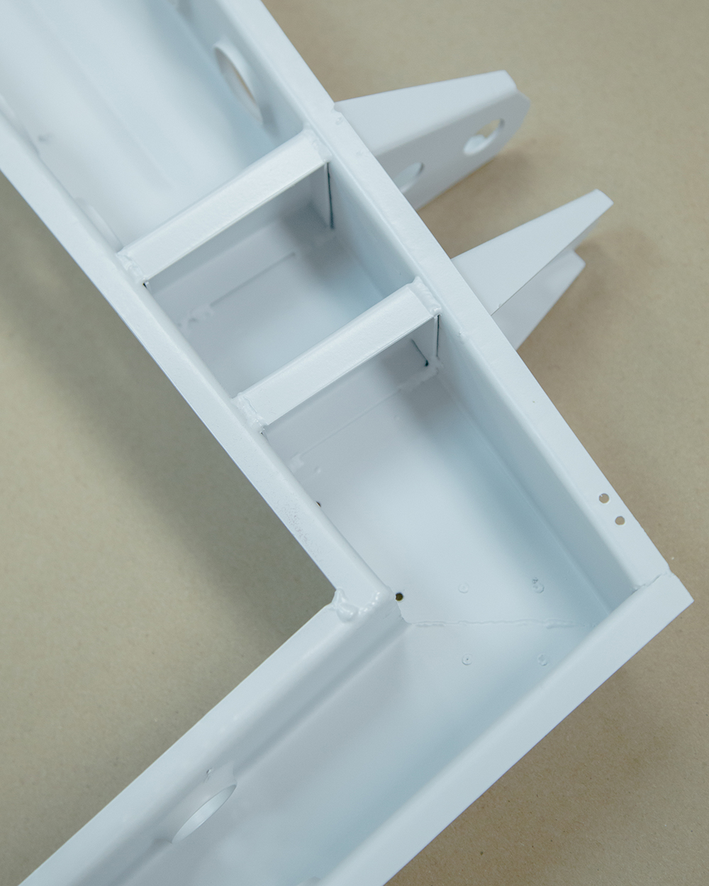
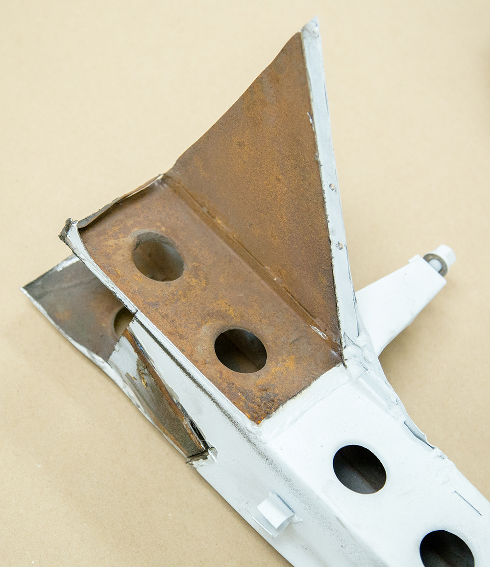
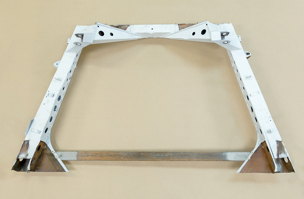
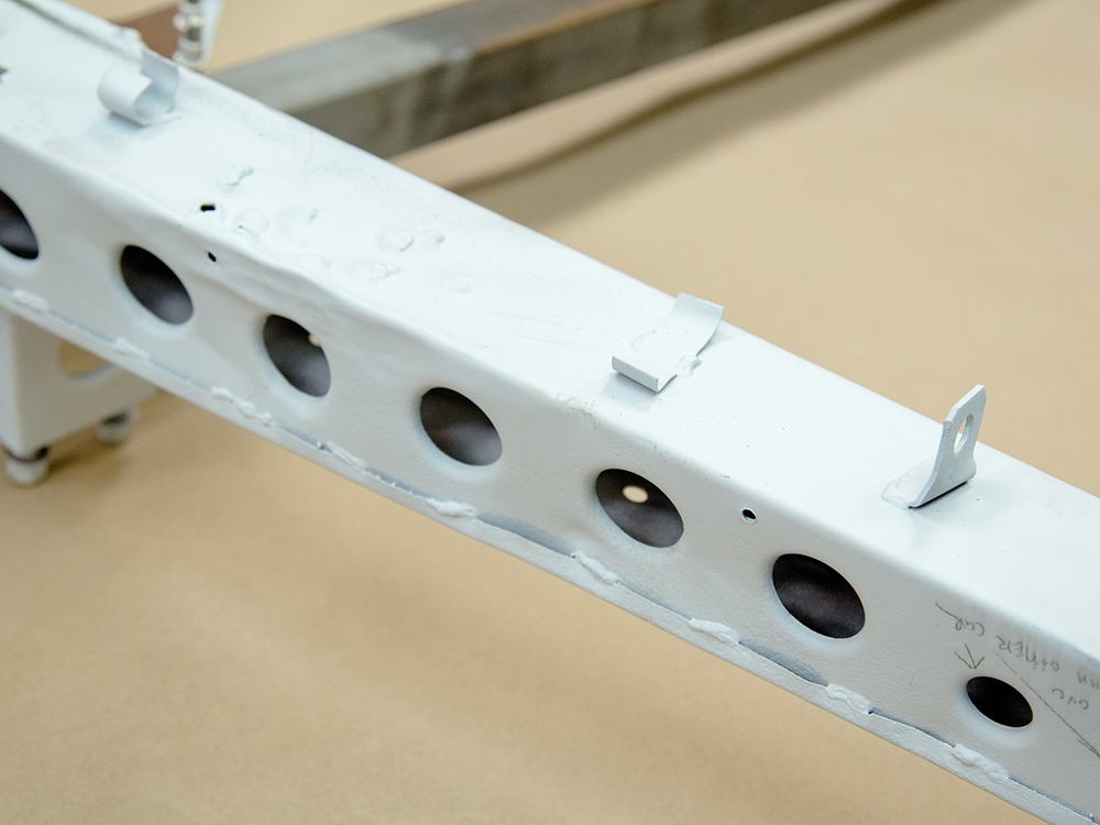
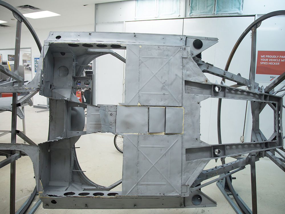
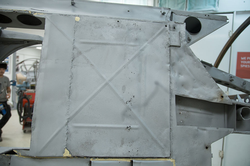
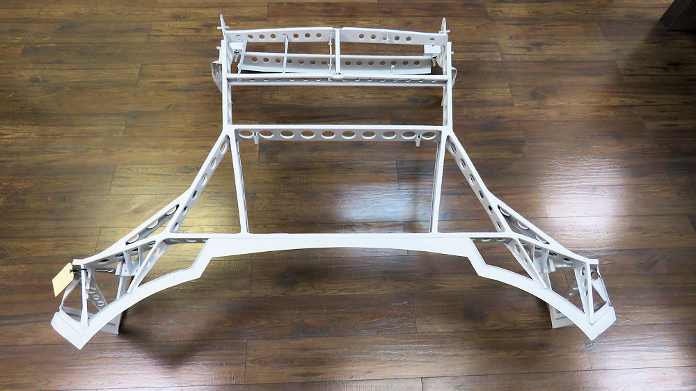
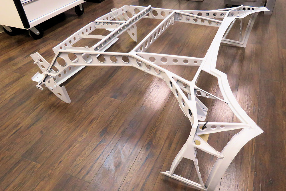
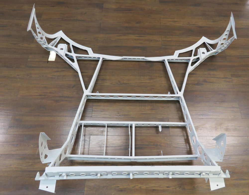
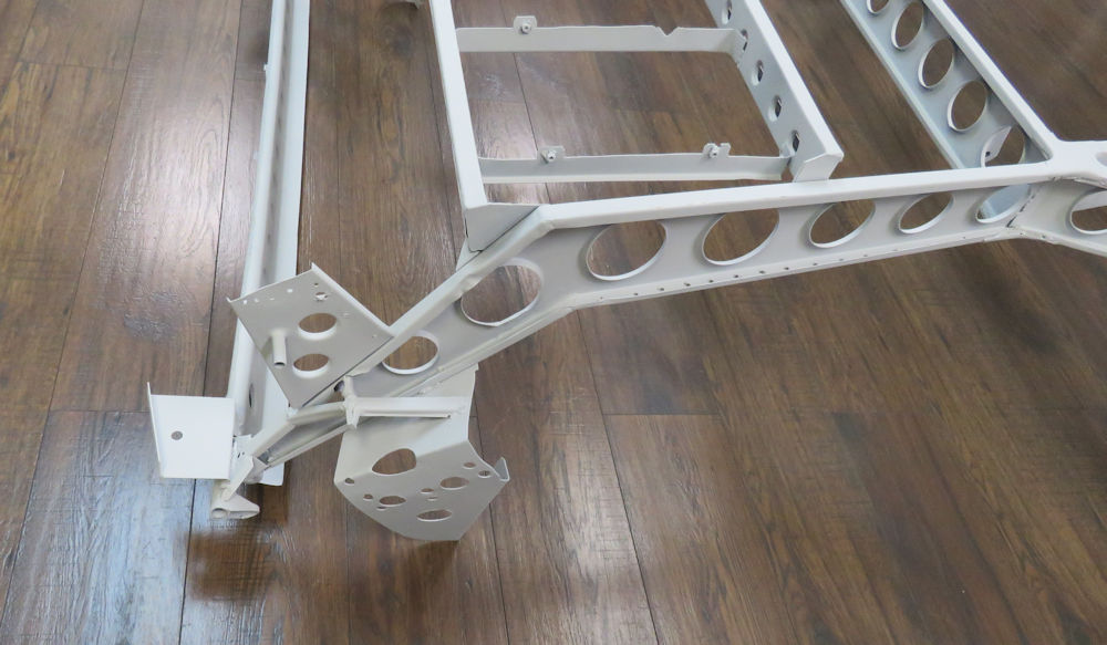
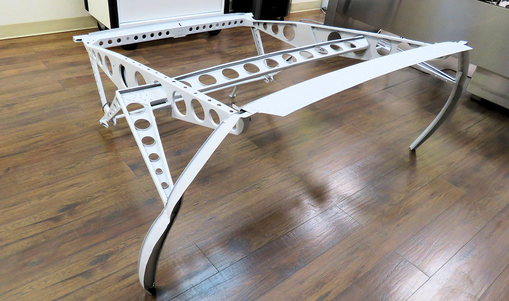
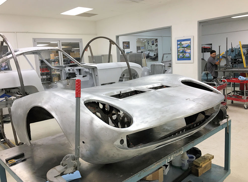
We have now
blasted the front and rear bonnet subframes back to bare
metal and sealed them with epoxy primer. Both subframes will
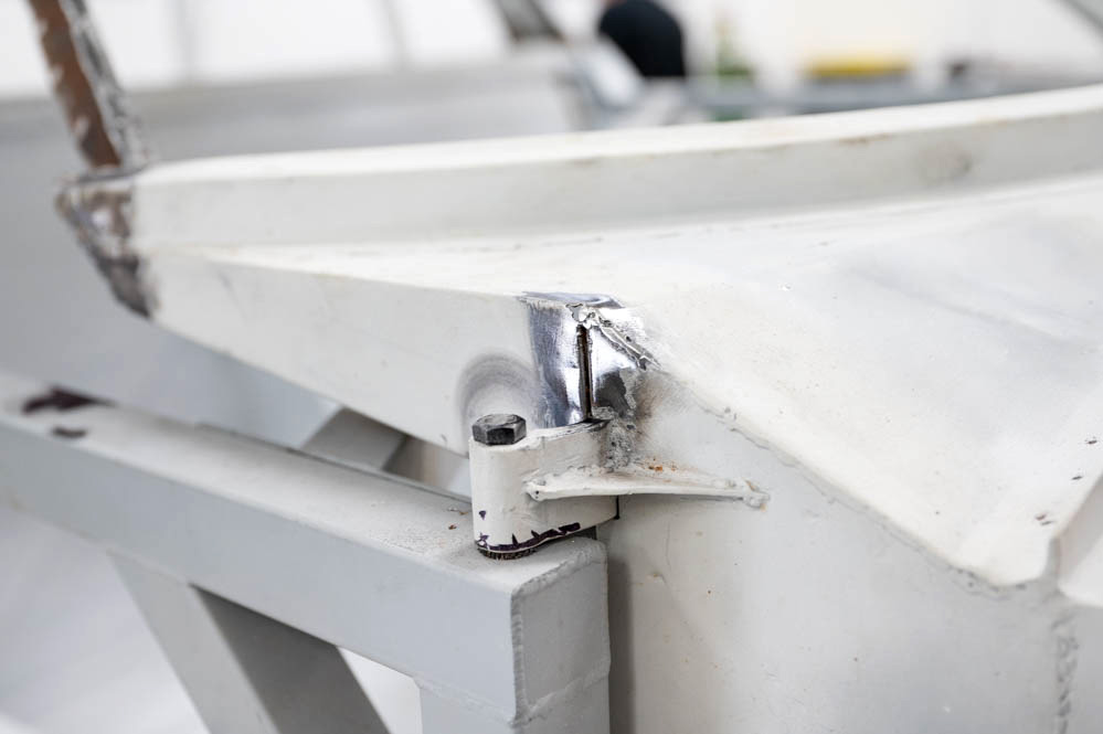
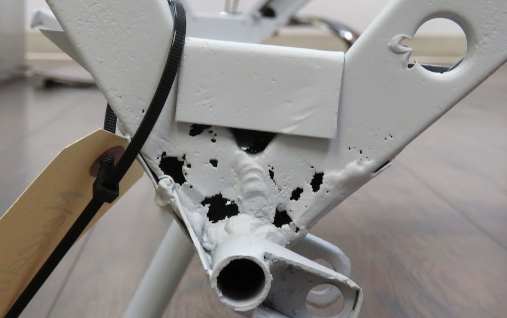
be repaired prior to painting, especially the rear subframe,
which is quite badly corroded in the area where the hinges
are attached.
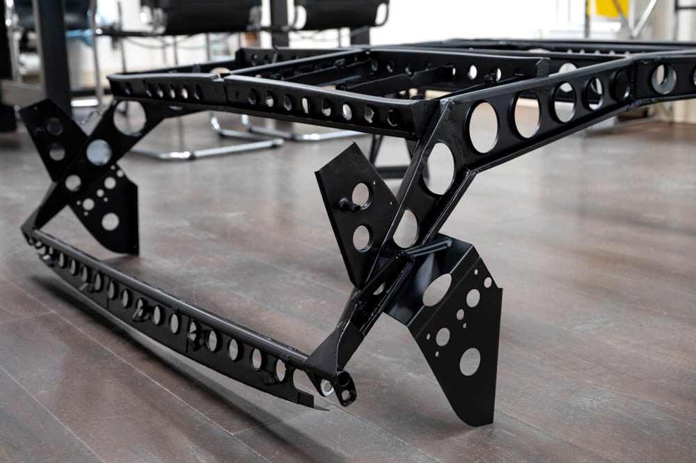
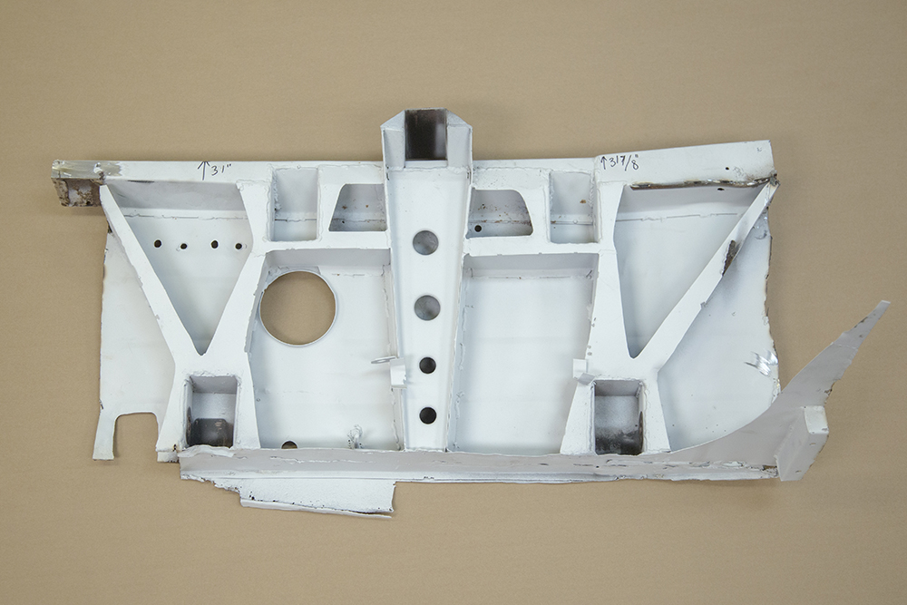
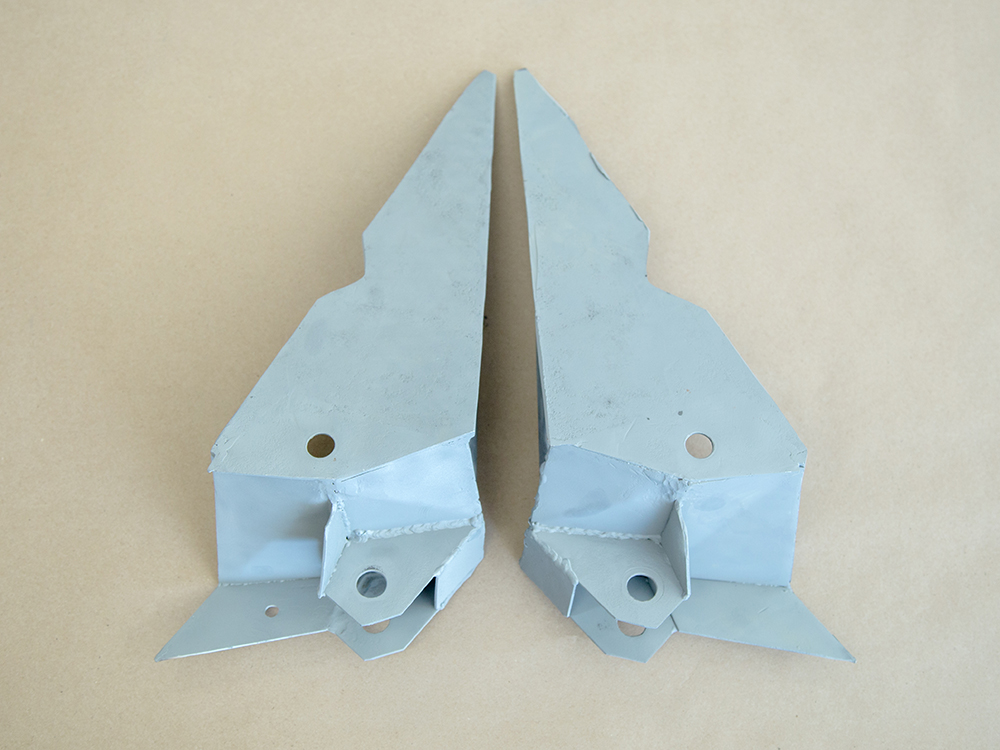
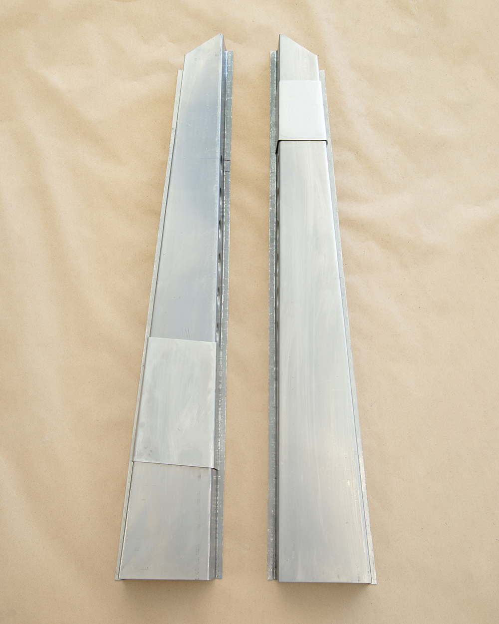
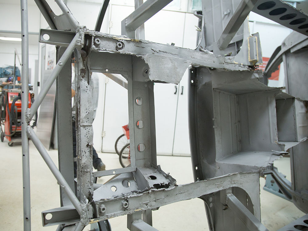
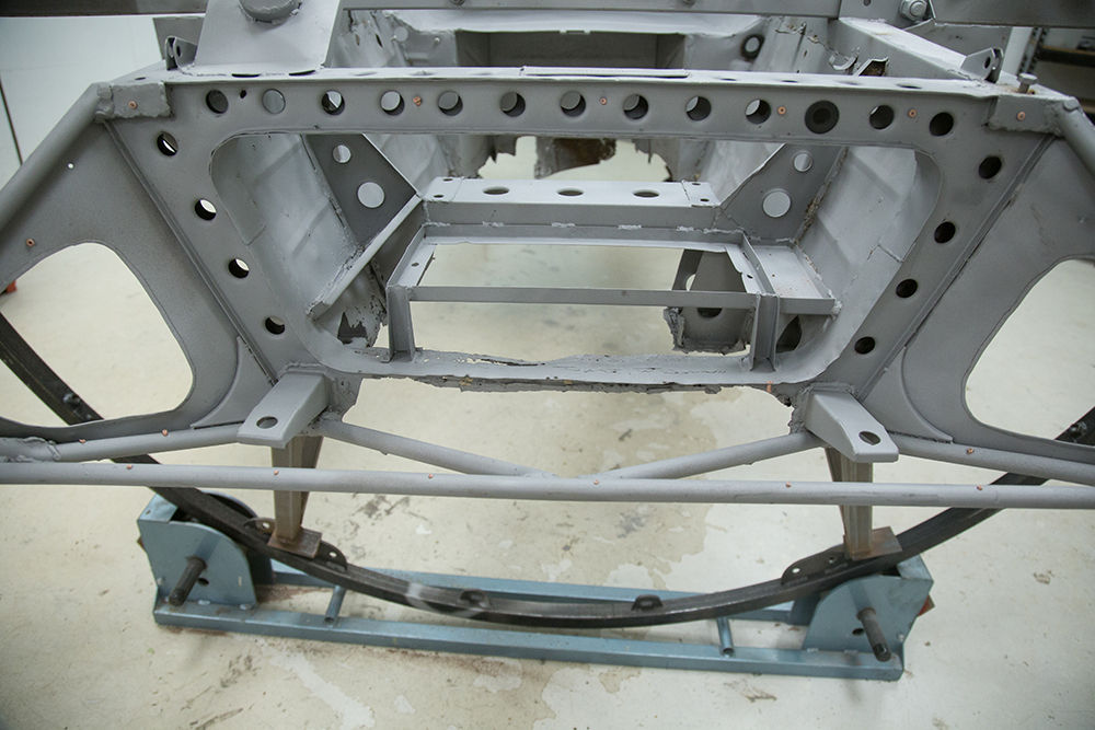
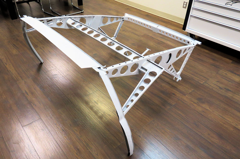
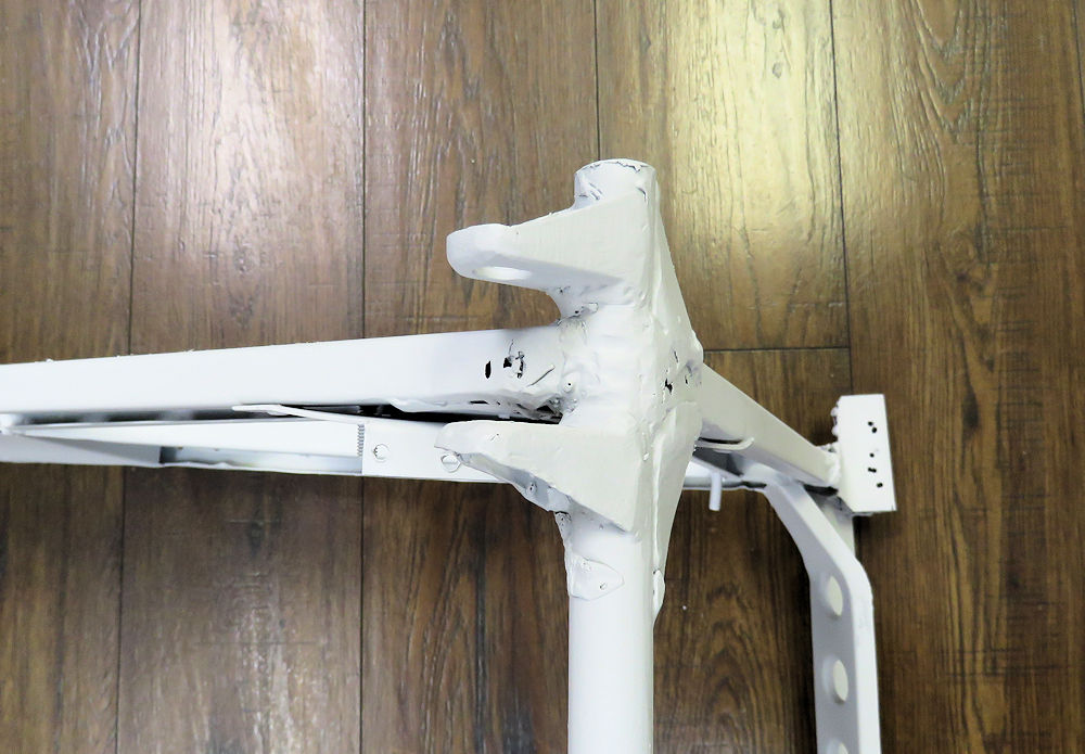
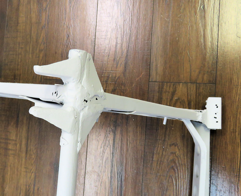
Front subframe is more complex than its
rear counterpart
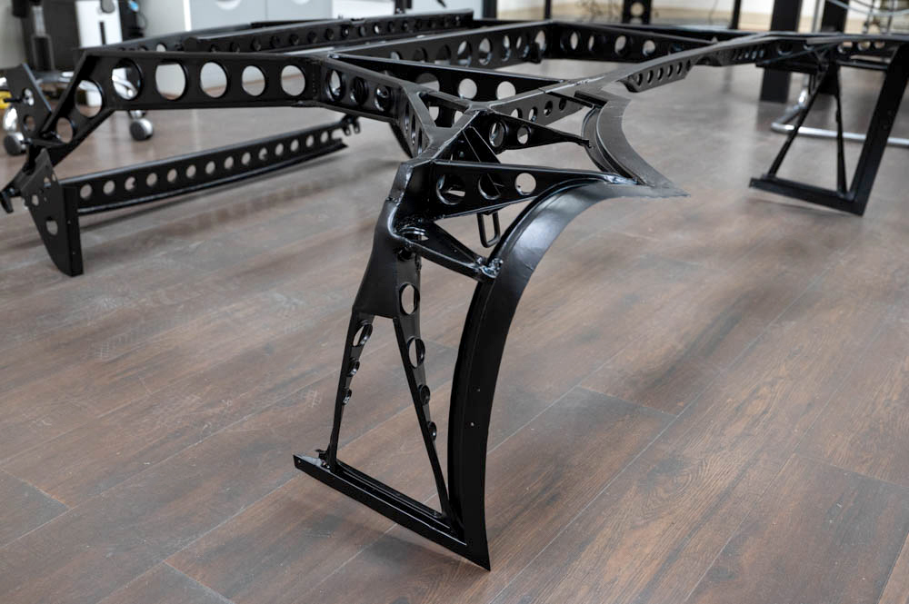
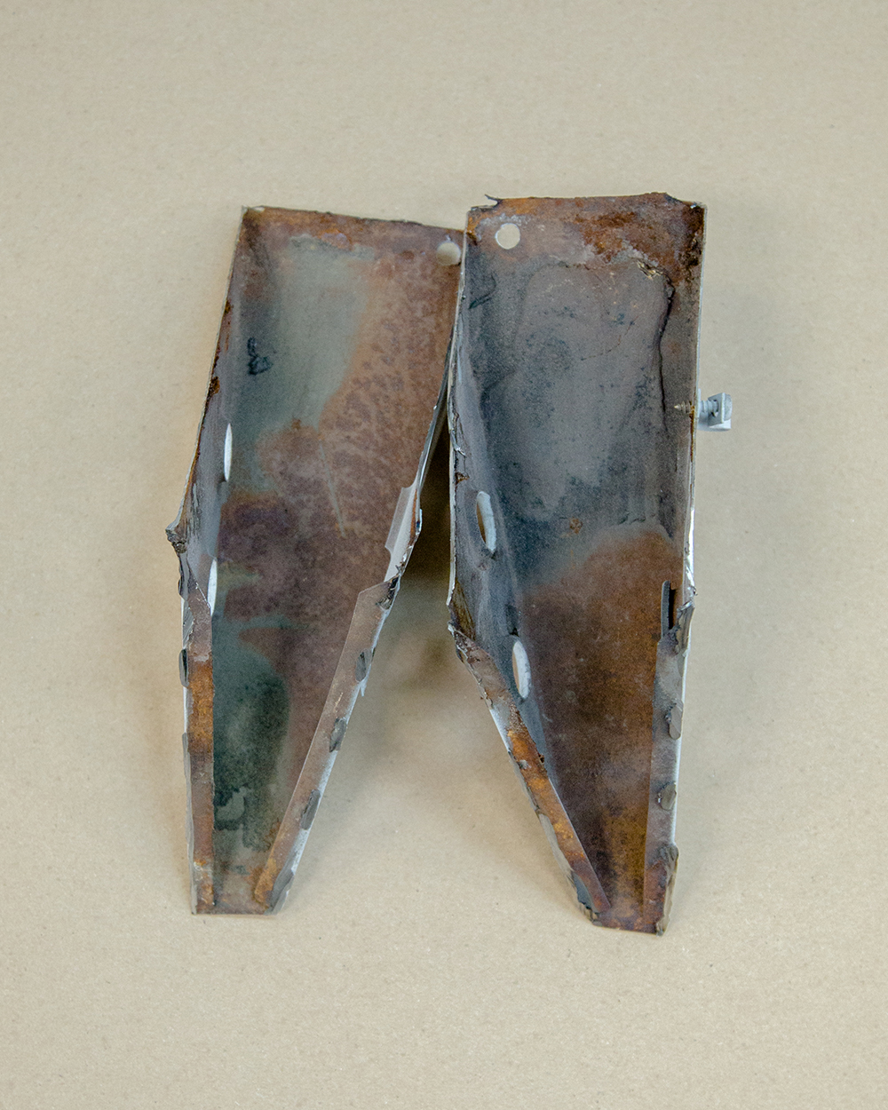
Rear subframe has some significant rust that
will
be dealt with prior to painting
Corrosion at the pivot point for the hinges
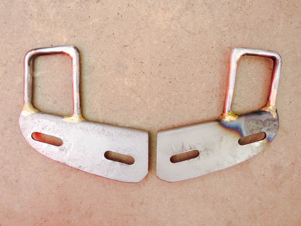
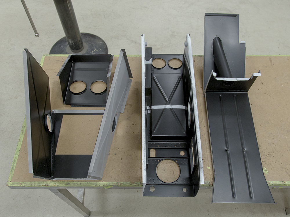
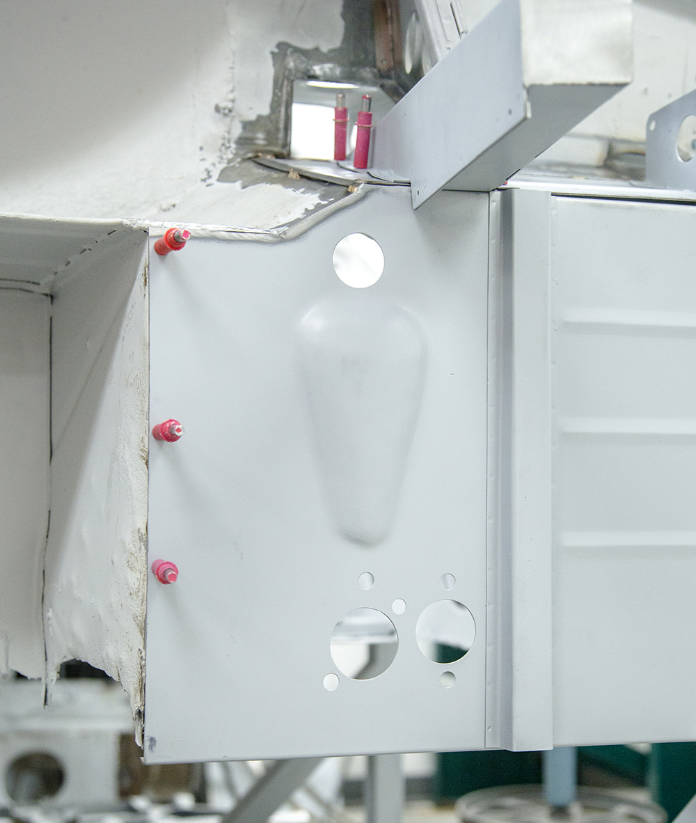
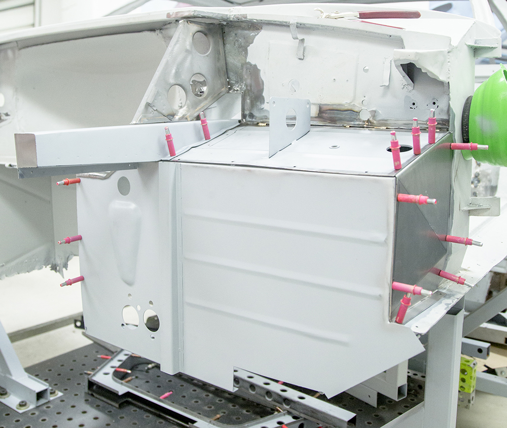
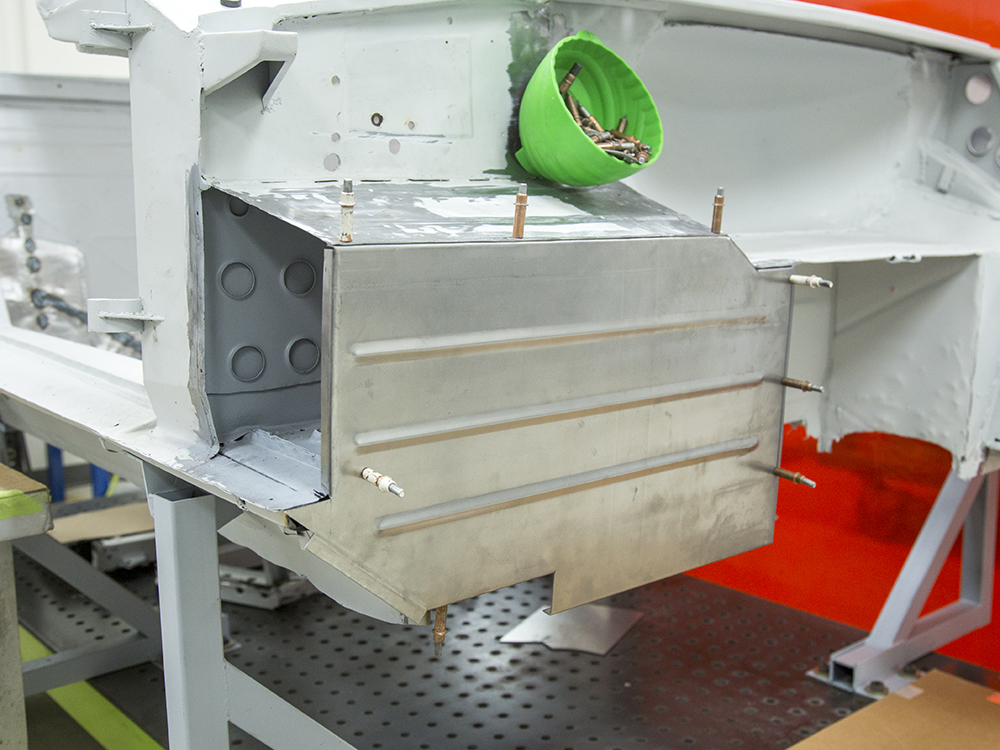
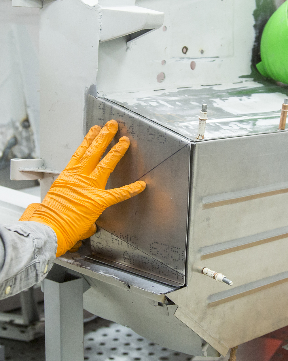
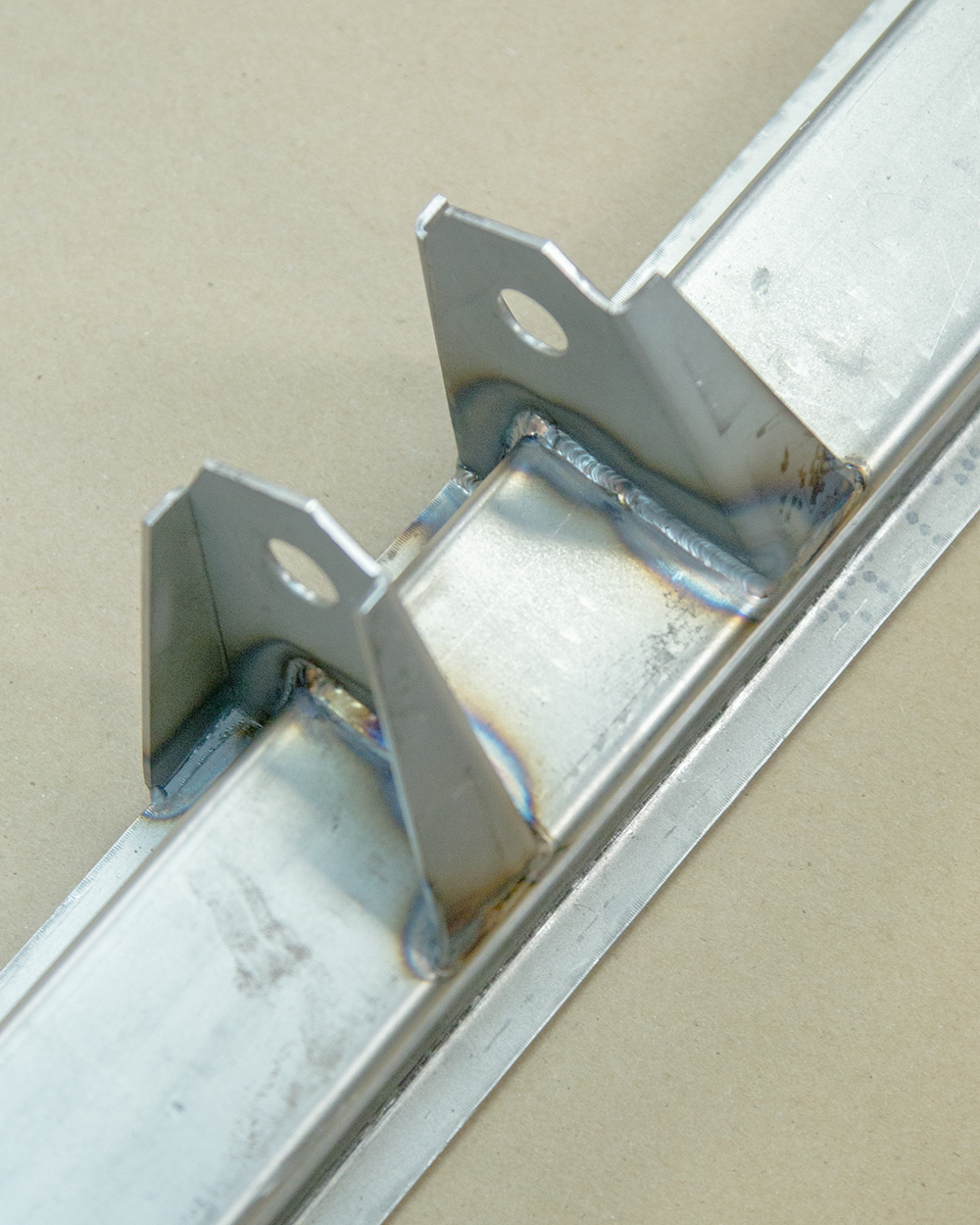
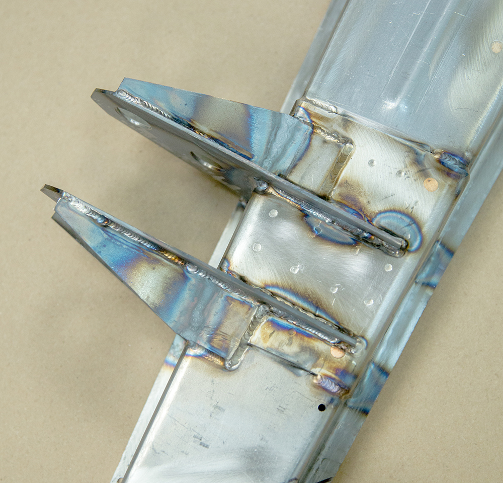
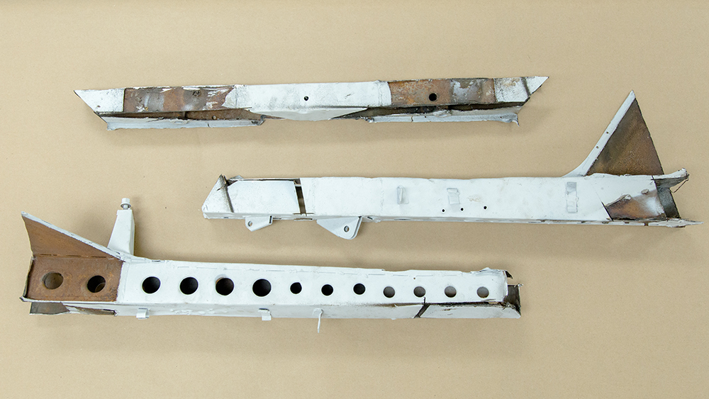
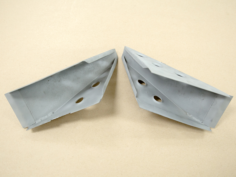
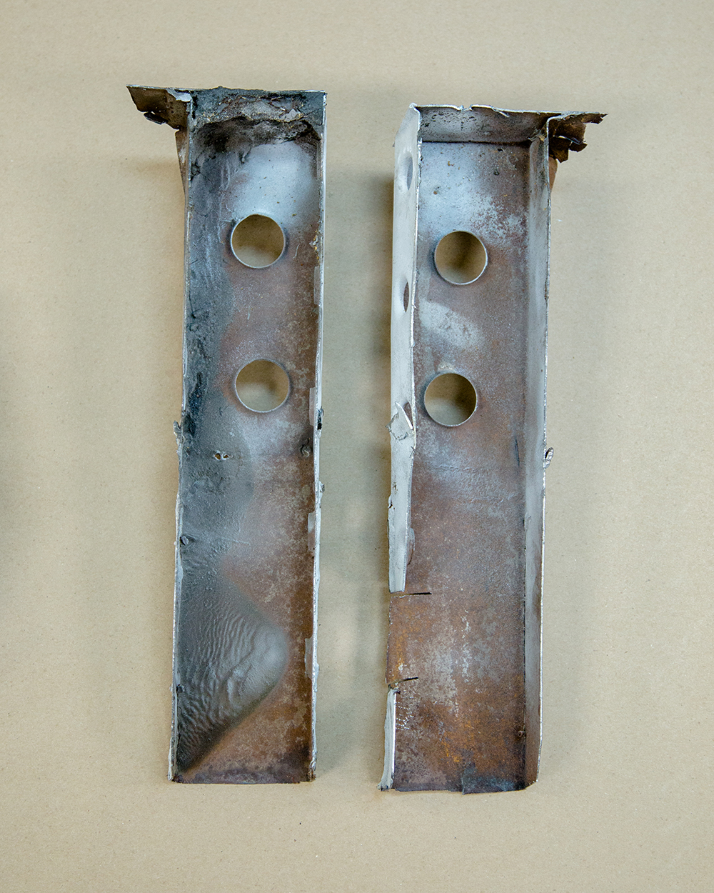
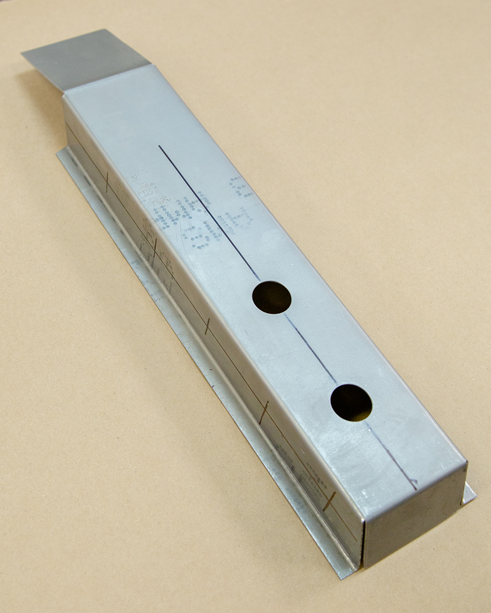
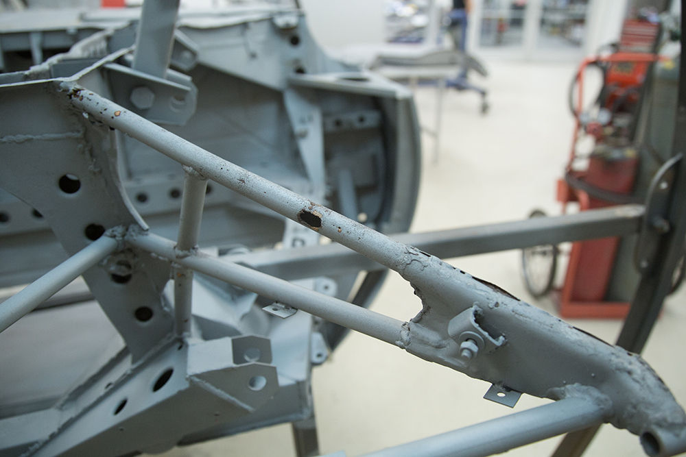
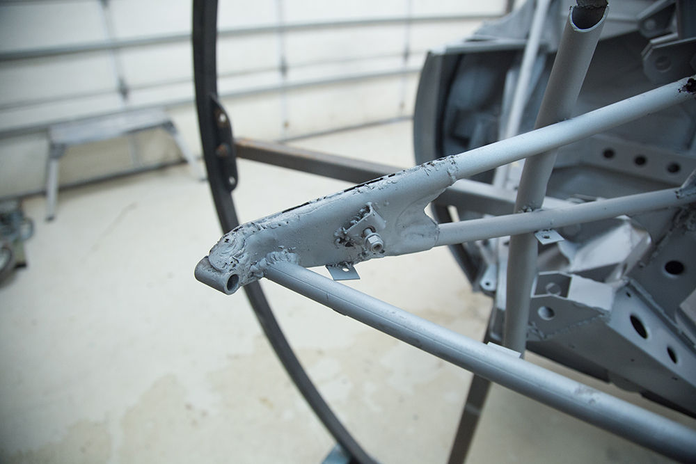
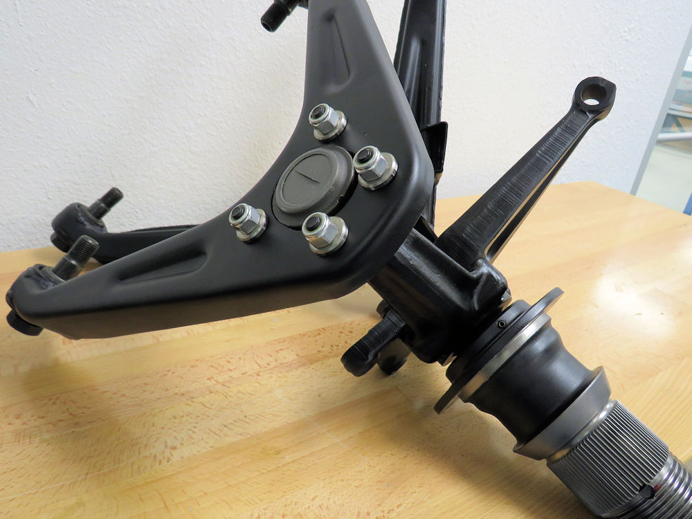
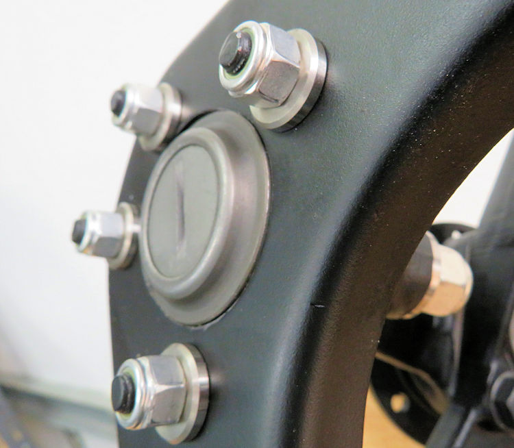
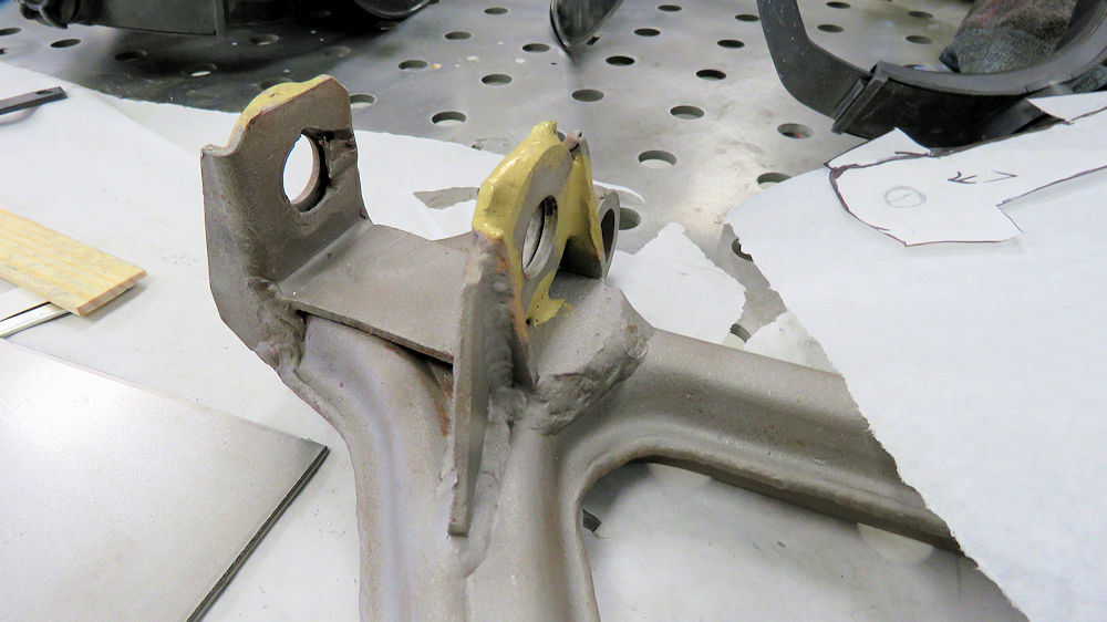
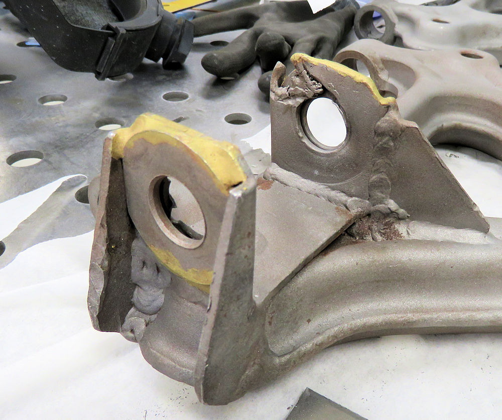
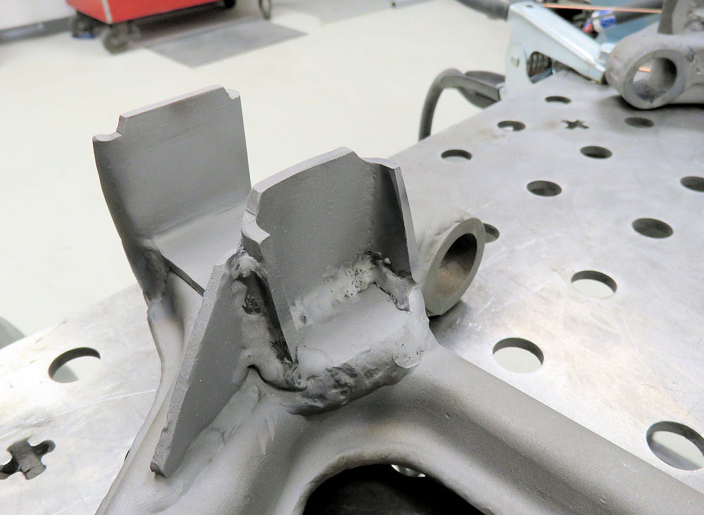
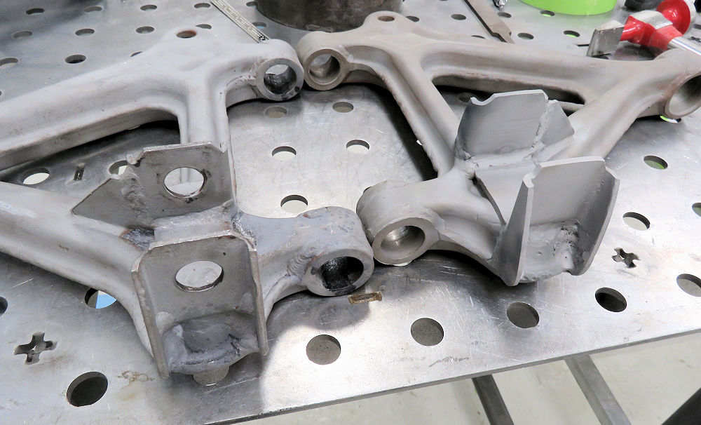
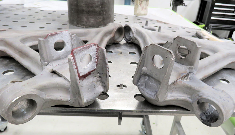
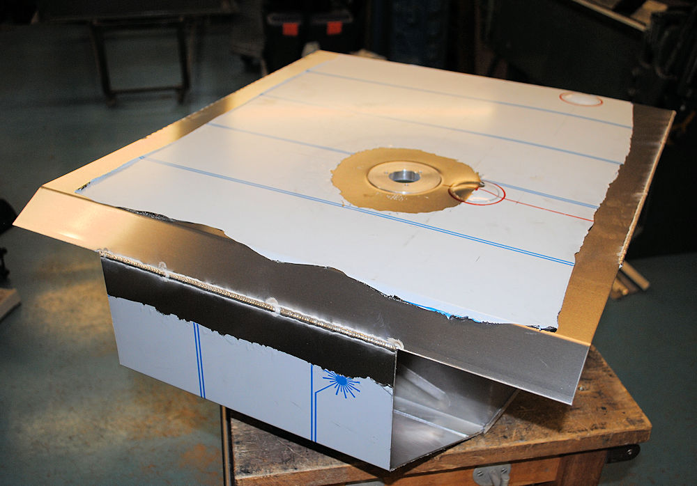
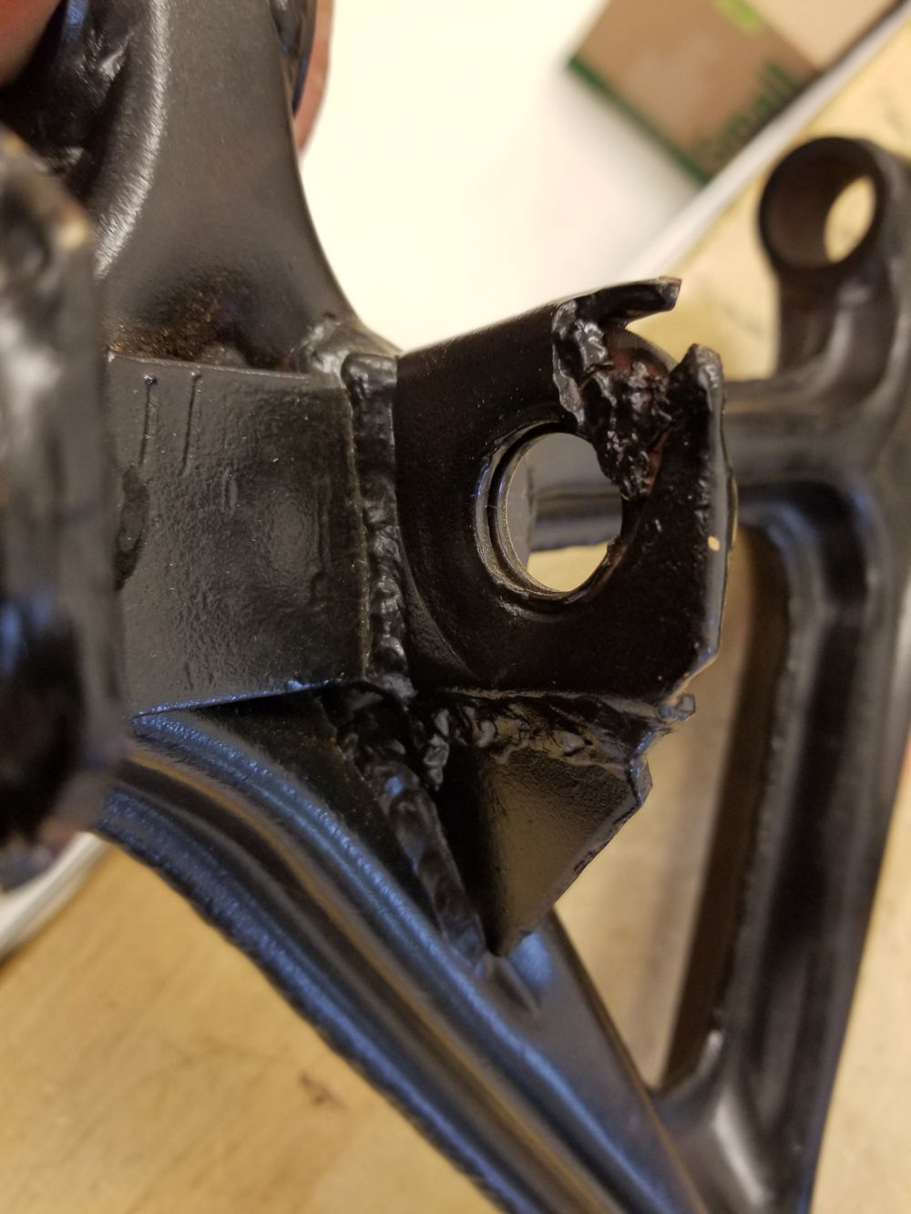
The following
photos show the reconstruction of one of the damaged
(previously repaired) control arms, and also an absolutely
beautiful new fuel tank.
Damaged control arm had been previously
repaired
by brazing washers around shock mounts
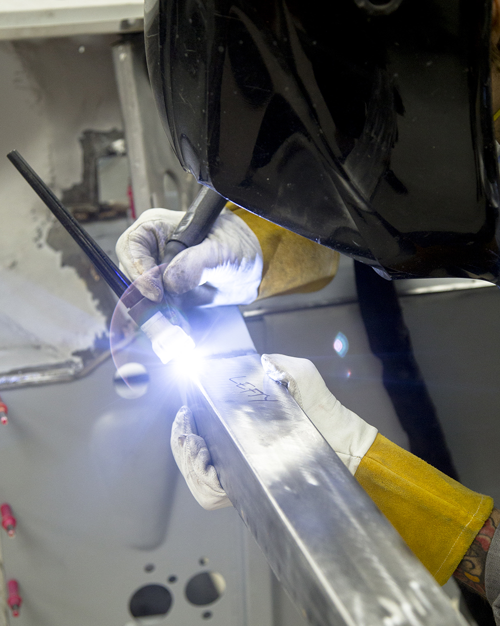
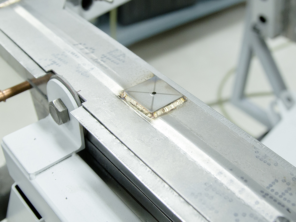
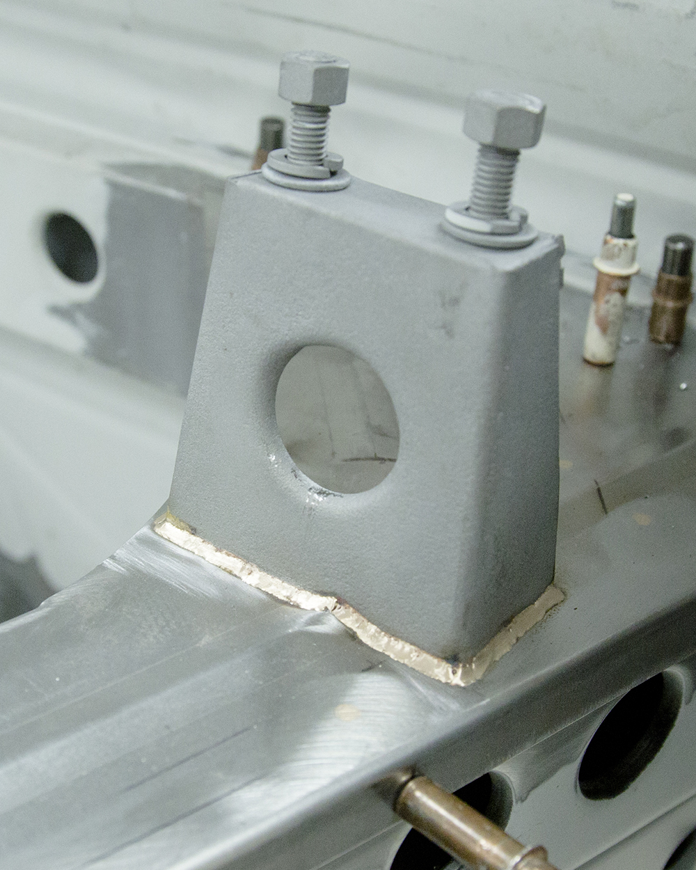
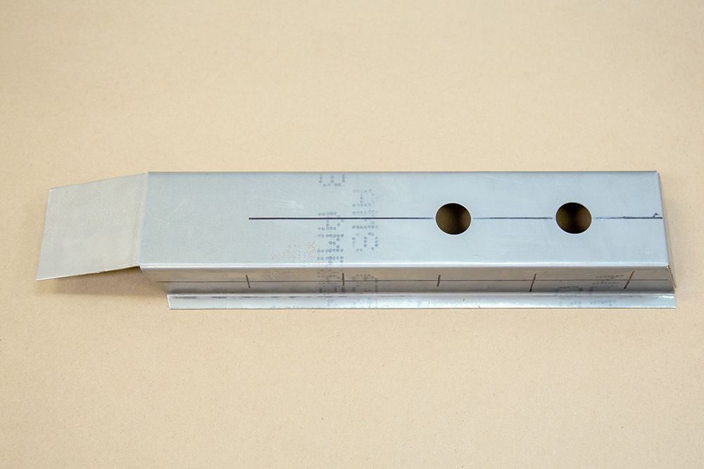
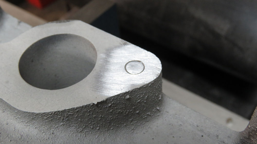
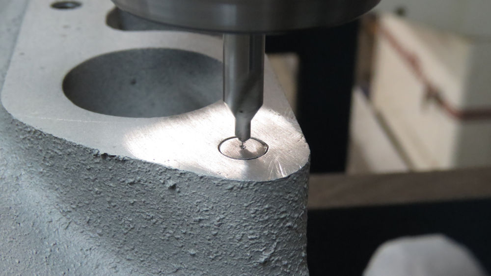
Fabricating a new shock mount
New shock mount welded in place
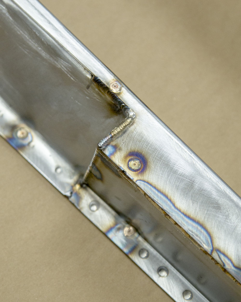
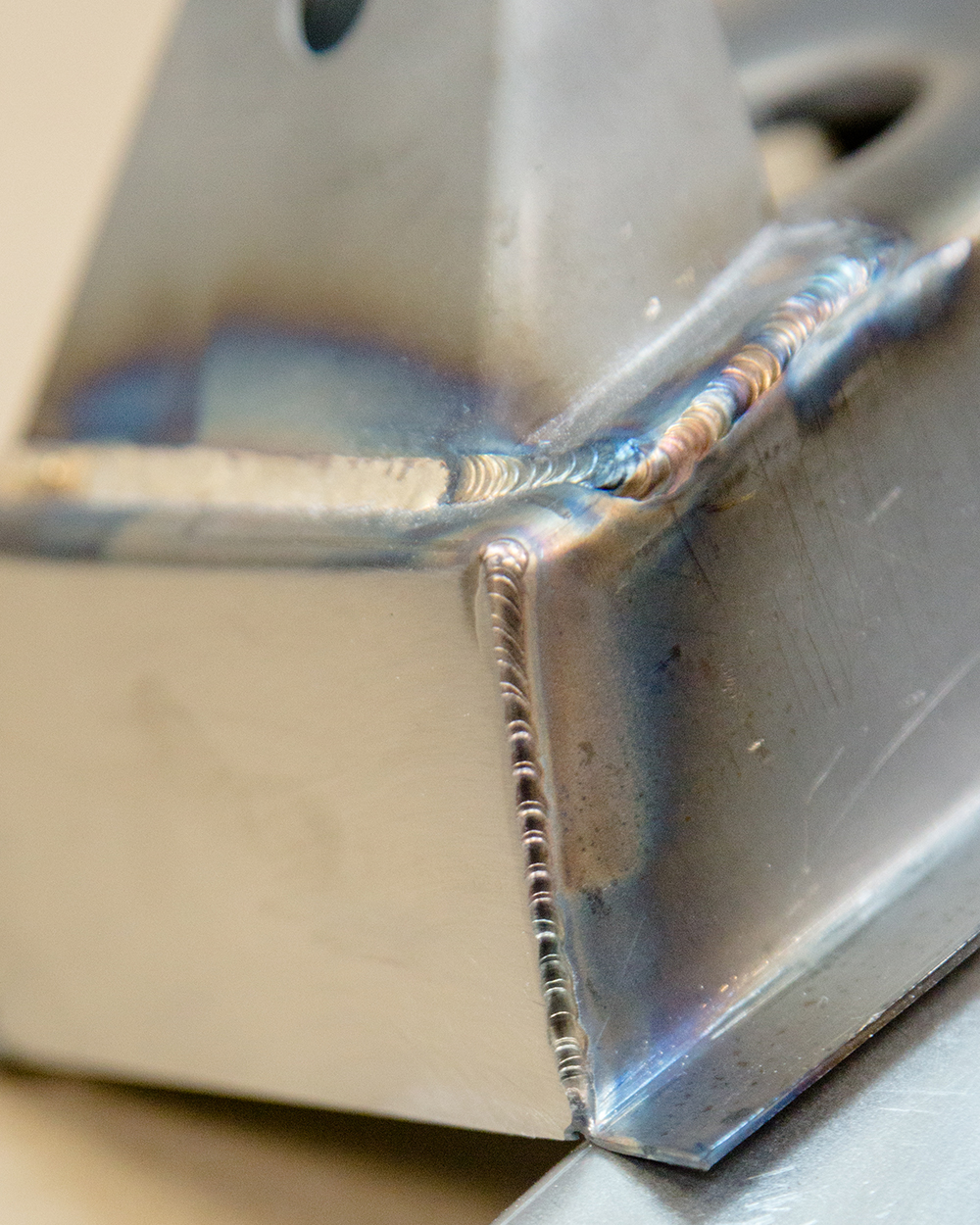
Factory did not clean back welds, so we left
our
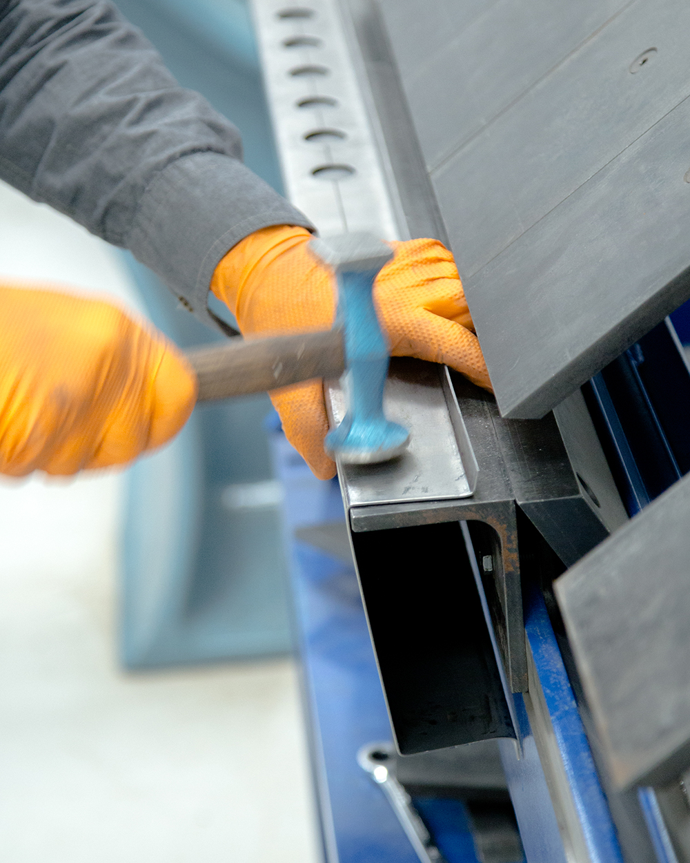
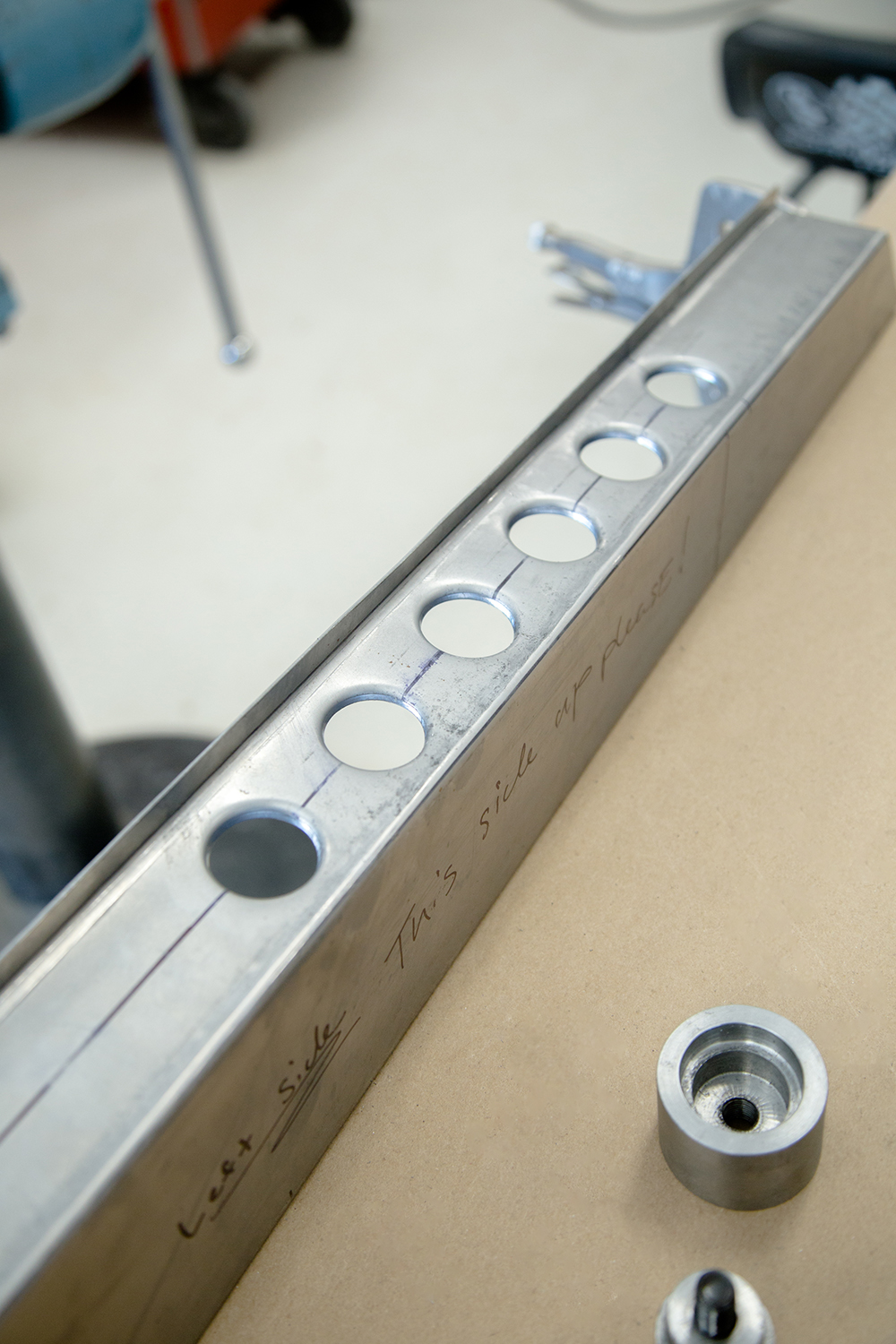
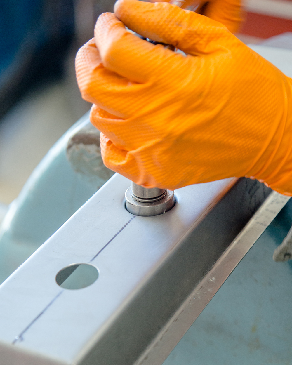
weld beads to look as original as possible
Shock mount holes indexed and drilled
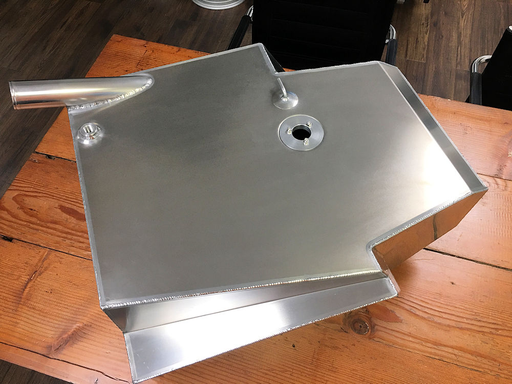
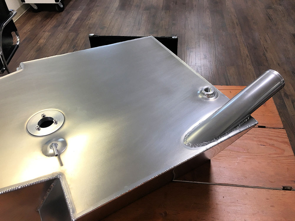
Fabricating the new fuel tank
The finished article
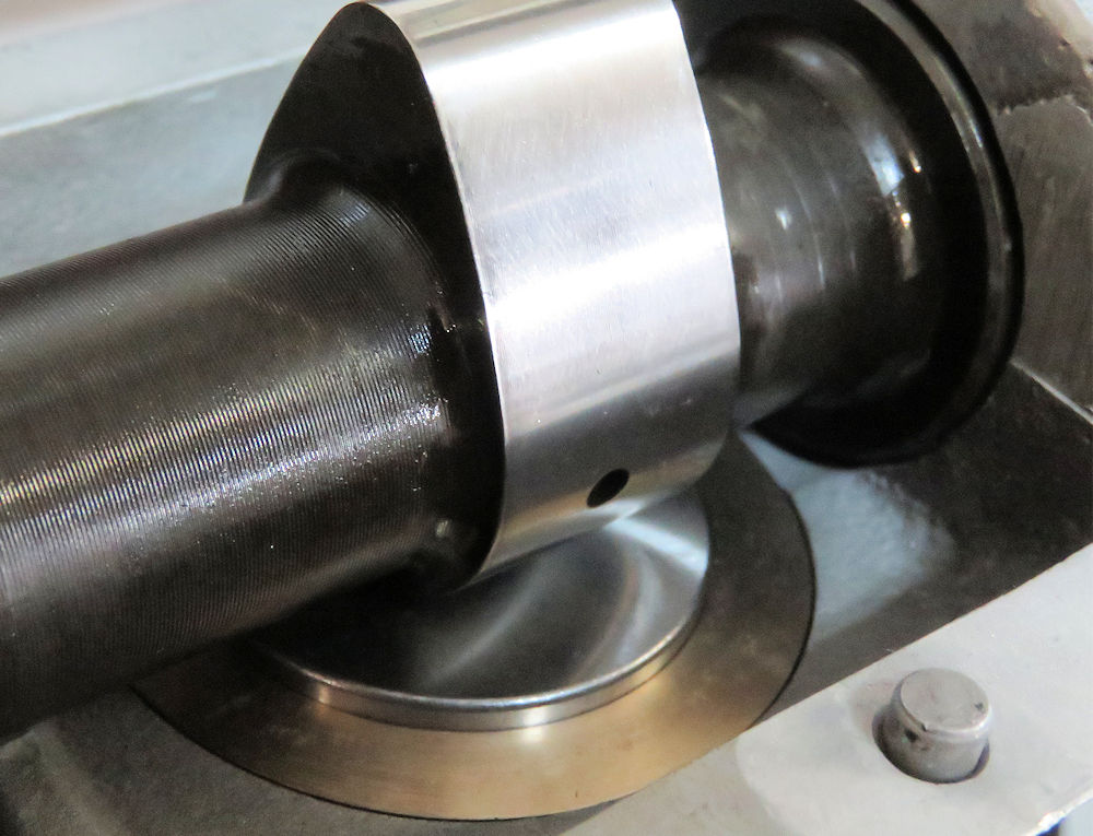
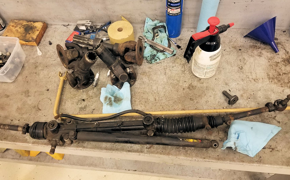
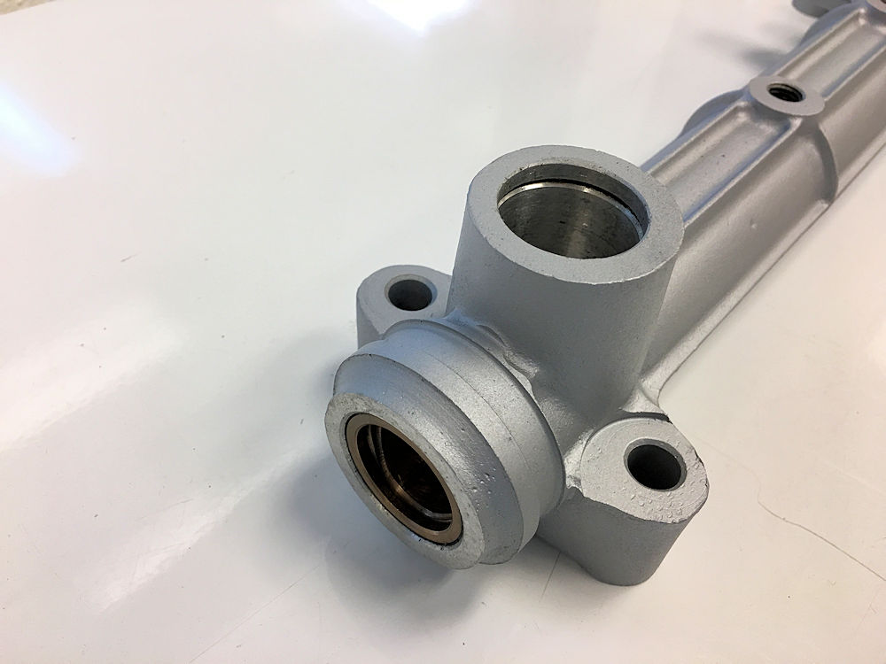
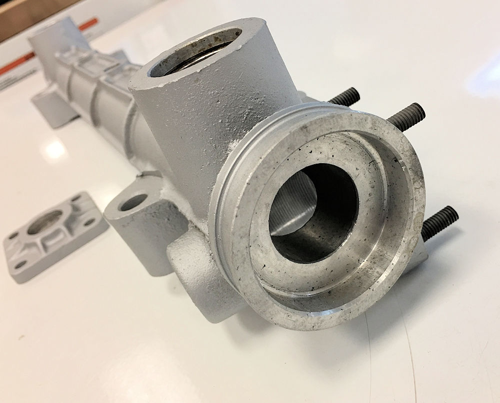
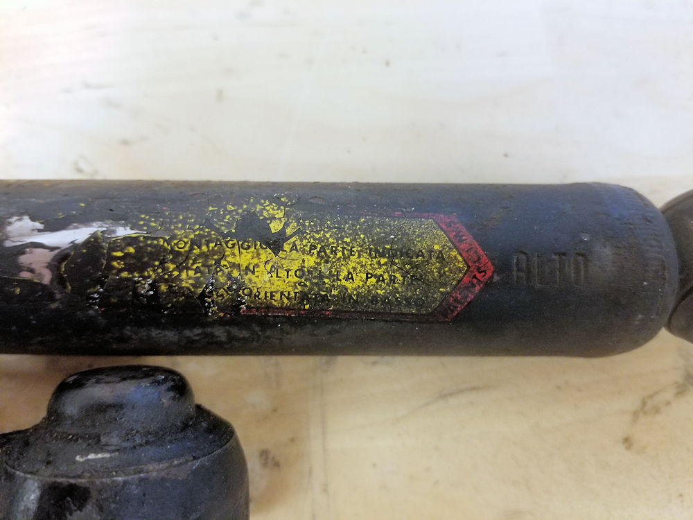
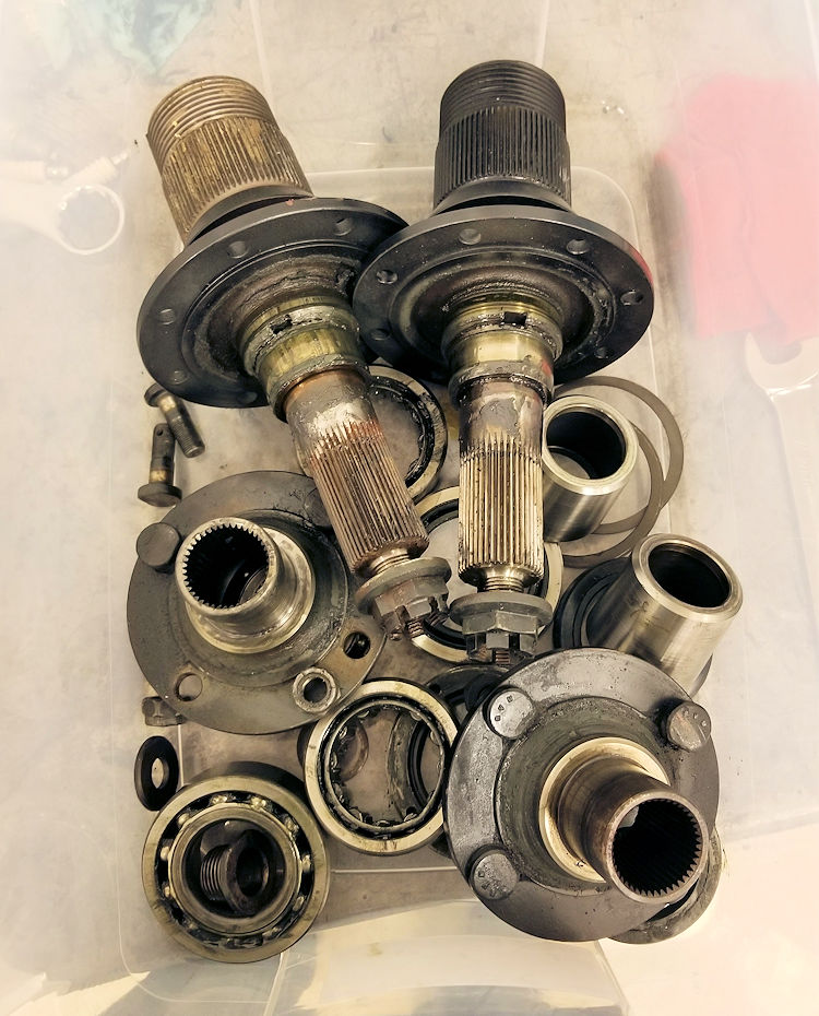
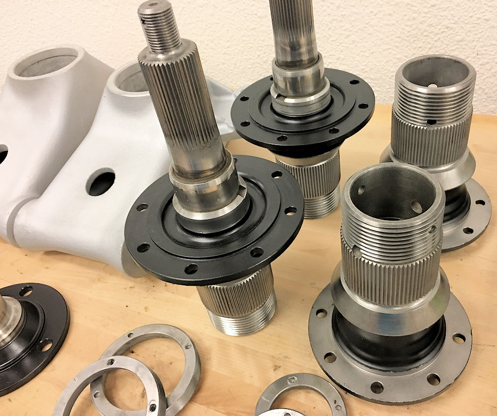
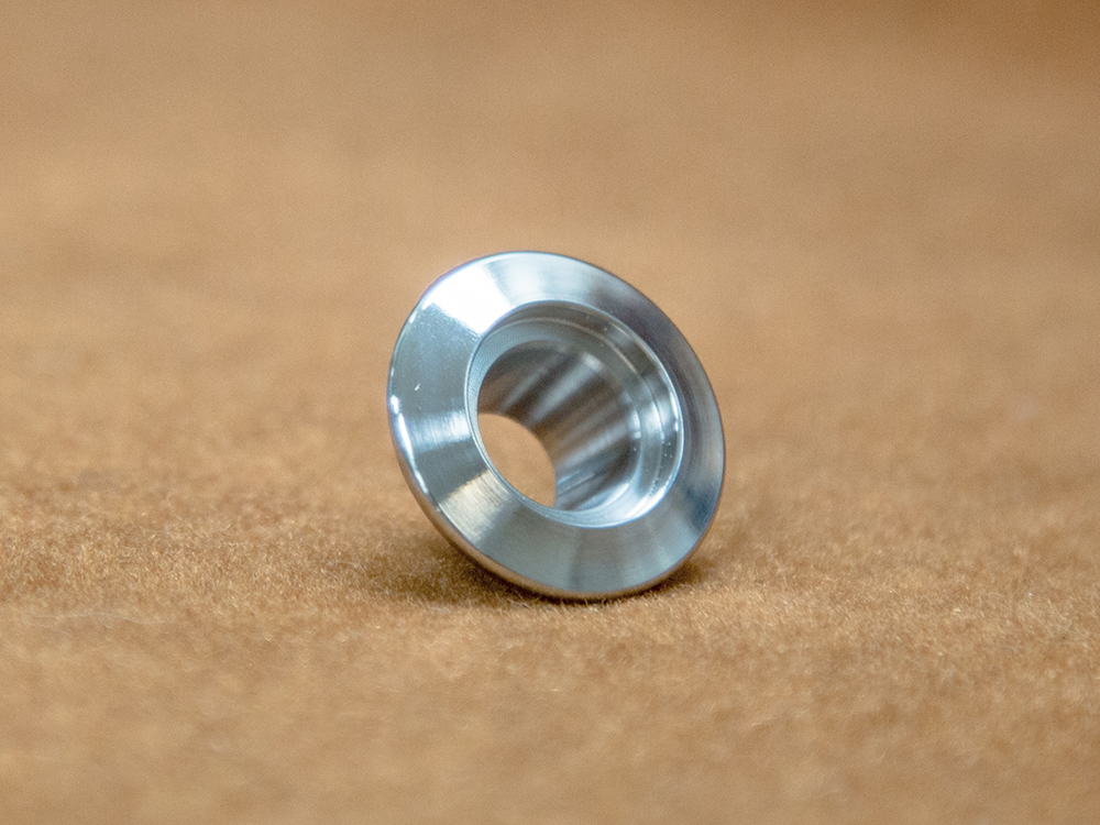
We are very
fortunate with this project that the car came to us with a
large number of extra spare parts. As we begin rebuilding
the suspension and steering, we have already needed several
of those replacement parts, including an alternative rear
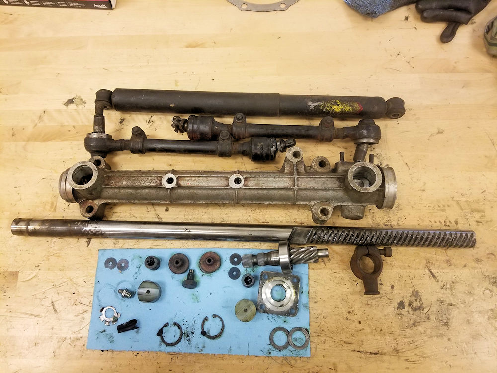
hub carrier and some major steering rack components.
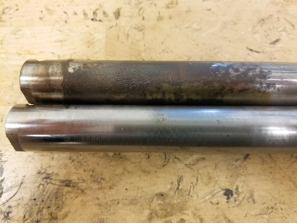
About to tear down the steering rack
Steering shaft is badly corroded
Fortunately we had a good used replacement
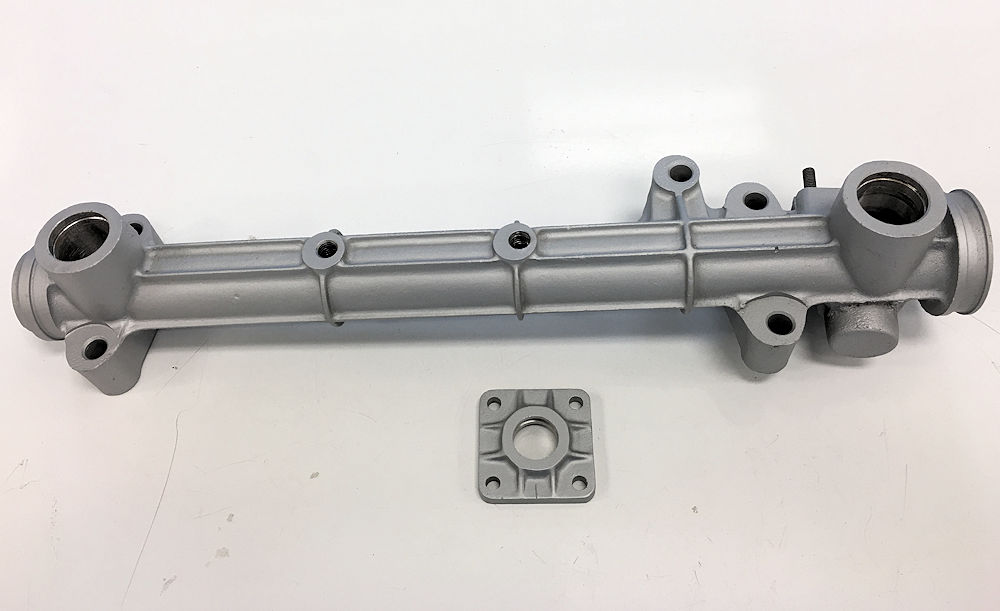
on hand
Rack housing blasted and cleaned up
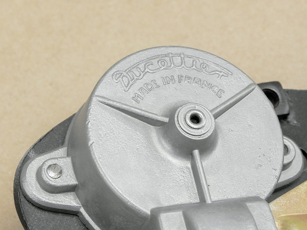
Original and rarely seen Oralian steering rack
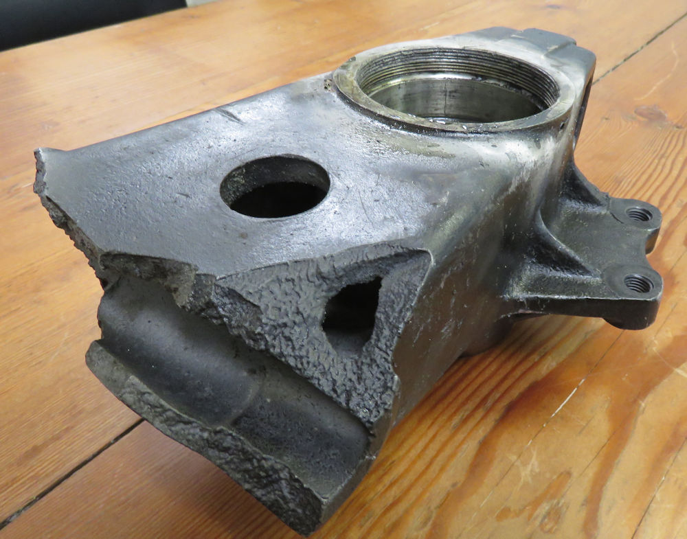
damper
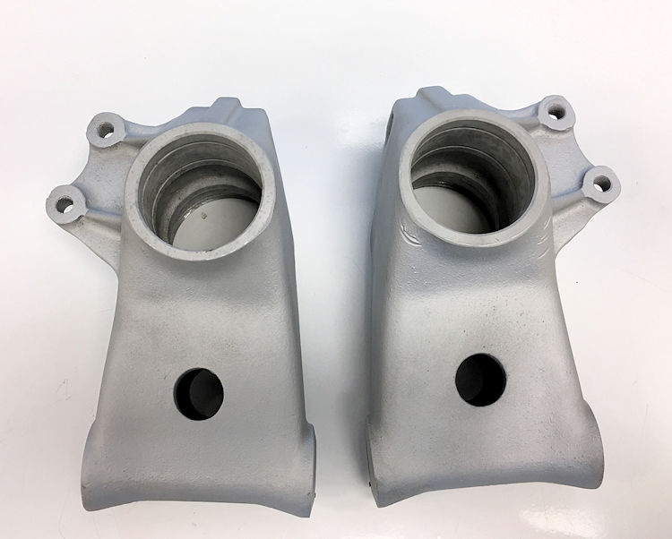
Badly damaged original rear hub carrier
Thankfully a good replacement hub carrier was
included in the spare parts that came with car
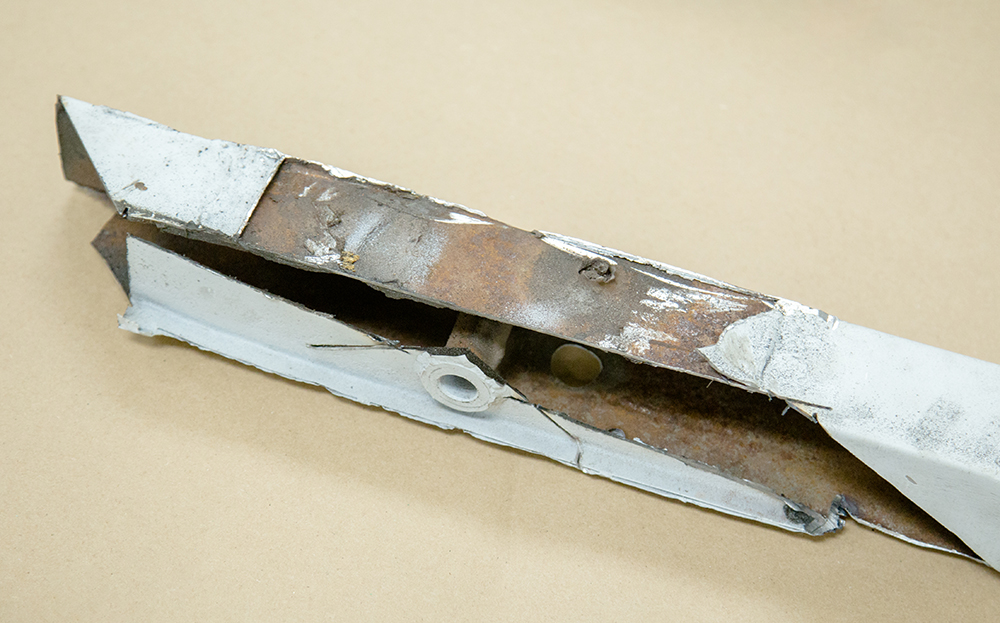
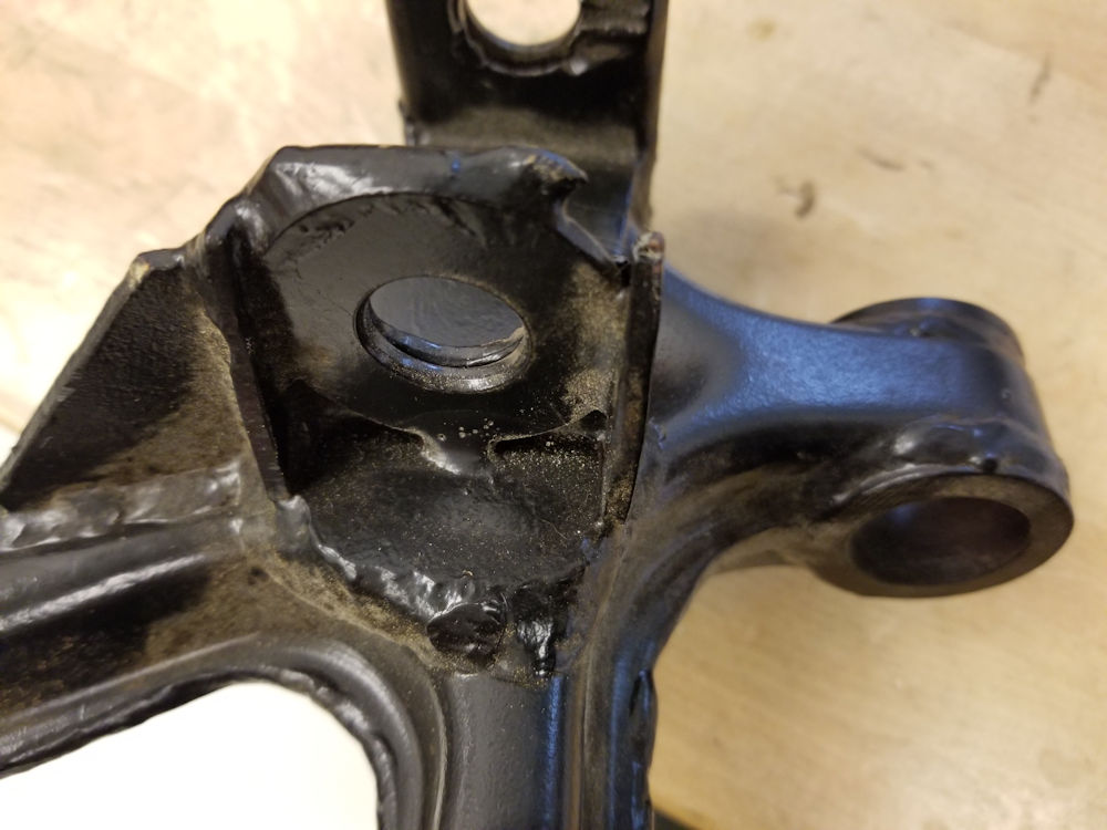
Suspension control arms have been crudely
repaired
and will need extensive repairs
This piece has a washer welded in place as
part of a
previous repair
Original Armstrong shocks will be replaced
with
Konis
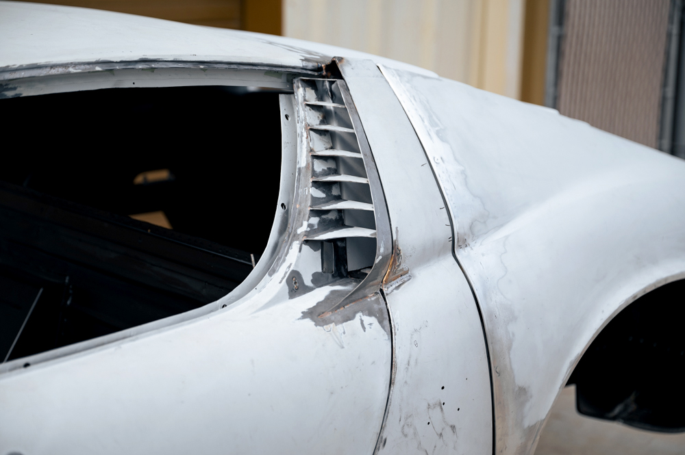
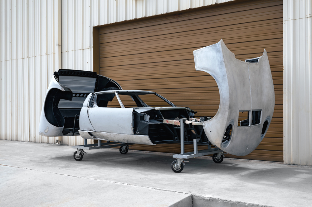
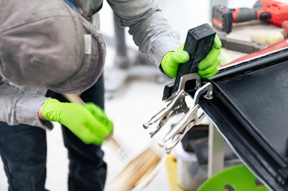
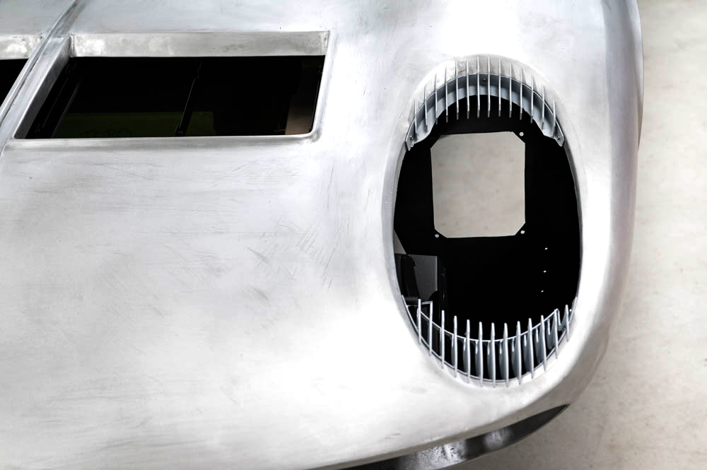
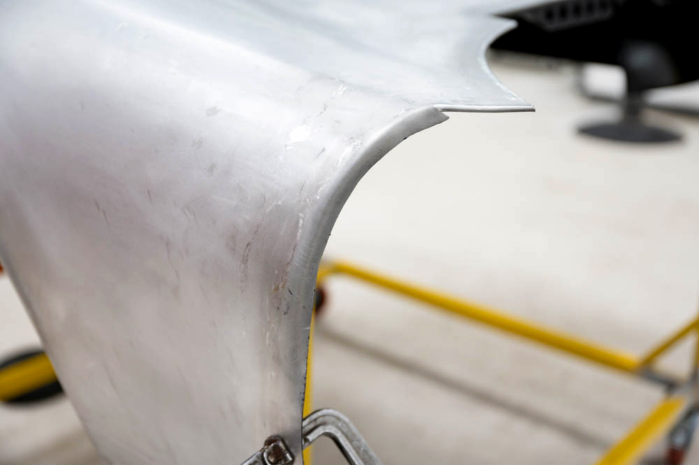
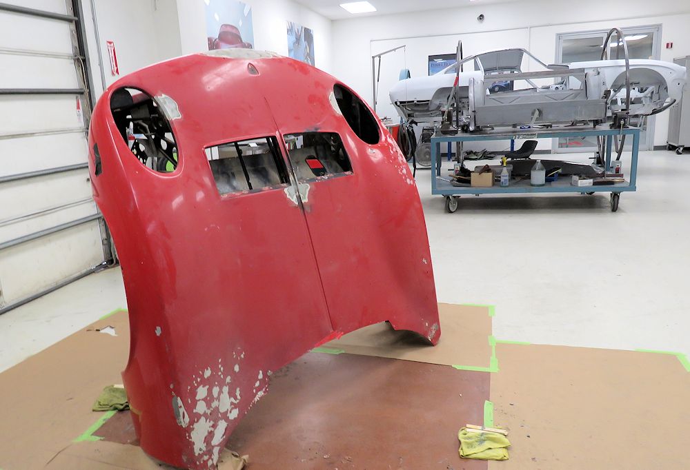
Lamborghini Miura
bonnets (and rear engine covers) are extremely susceptible
to galvanic corrosion because of the way the aluminum outer
skin is fitted over the top of a lightweight steel subframe.
The following sequence of photographs show the removal of
the bonnet outer skin revealing significant corrosion in the
outer flanges of the aluminum panel.
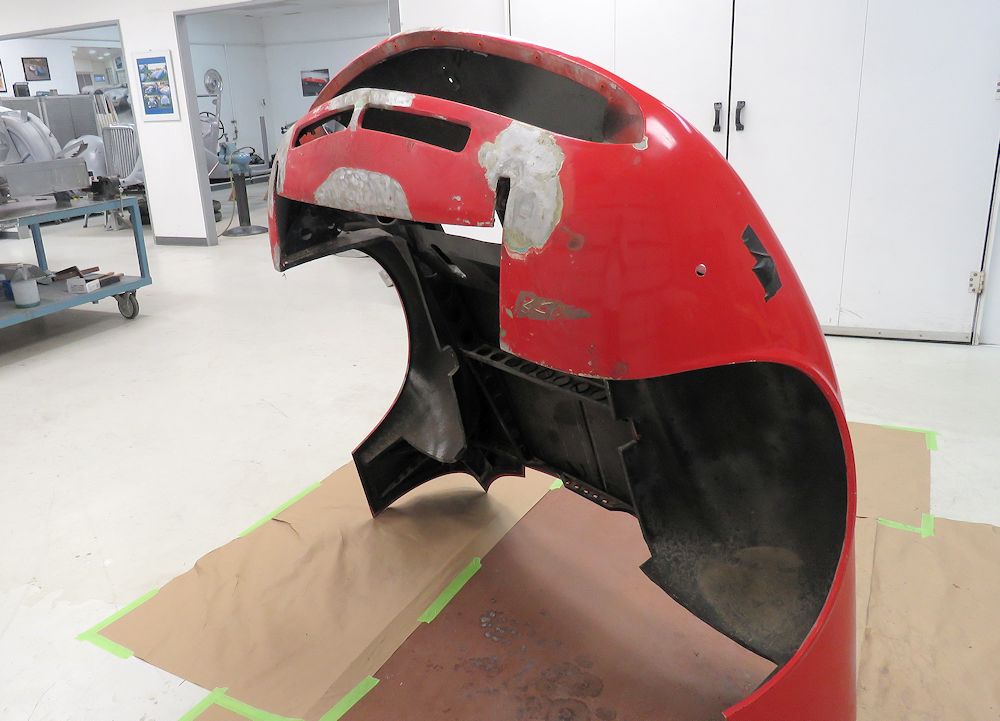
Preparing to de-skin the Miura bonnet
Rivets are first drilled out
Folding back the alloy out flanges reveals
significant corrosion
Galvanic corrosion is present wherever steel
meets
aluminum
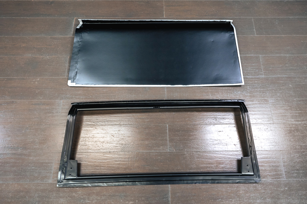
Lifting away the outer alloy skin
Extremely lightweight steel bonnet skeleton
The alloy bonnet skin weighs 32 lbs
Interesting to note that the chassis black
paint was
applied AFTER the subframe and outer skin
were assembled together
The front wheel arches must have been
installed
prior to any black paint being applied
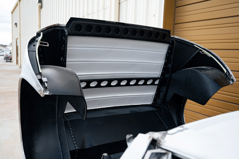
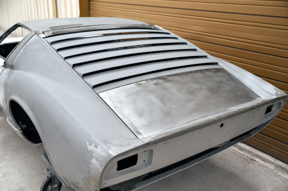
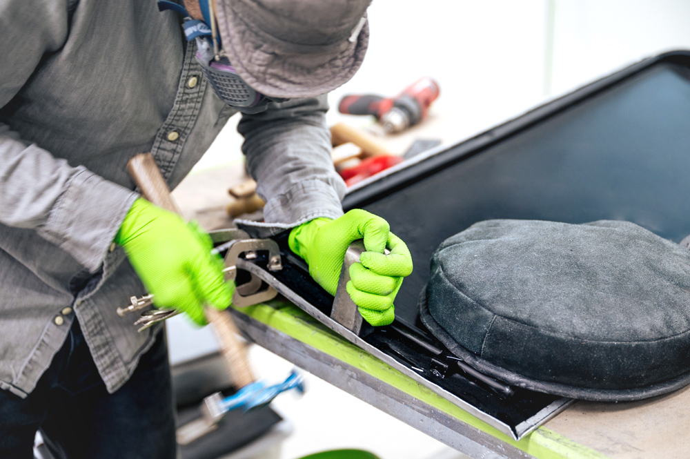
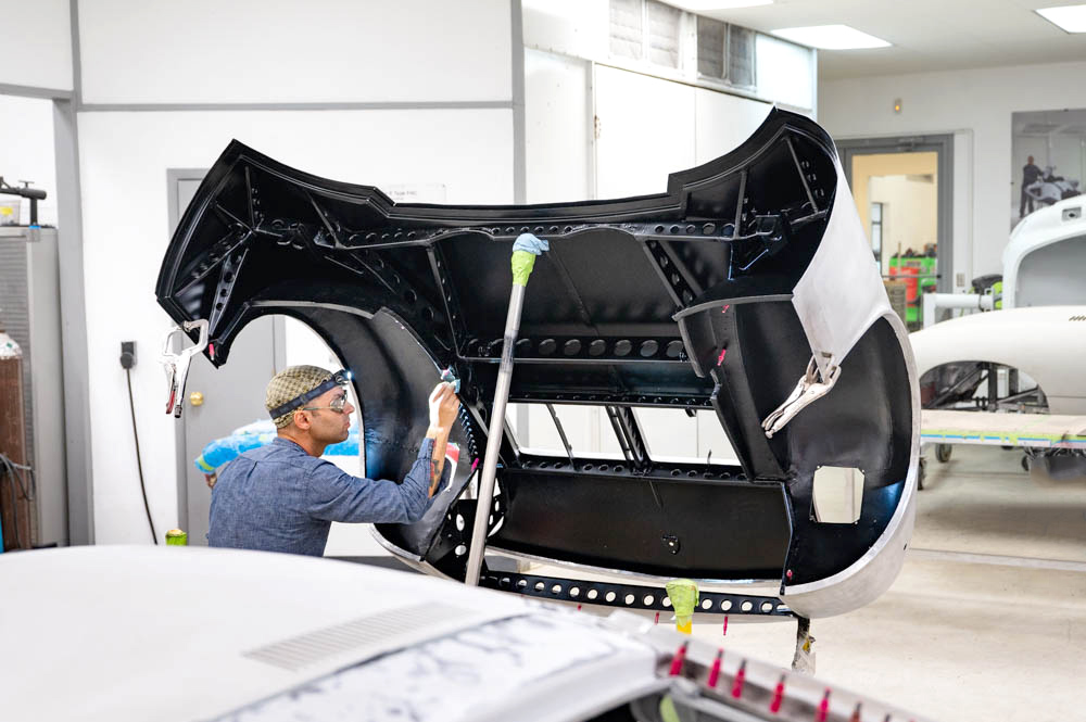
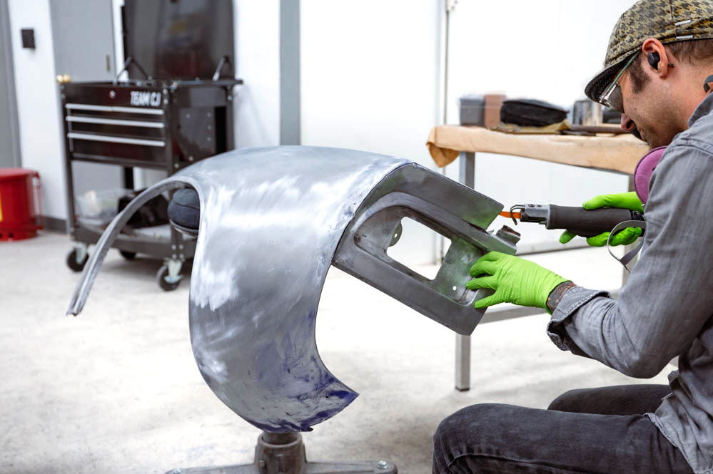
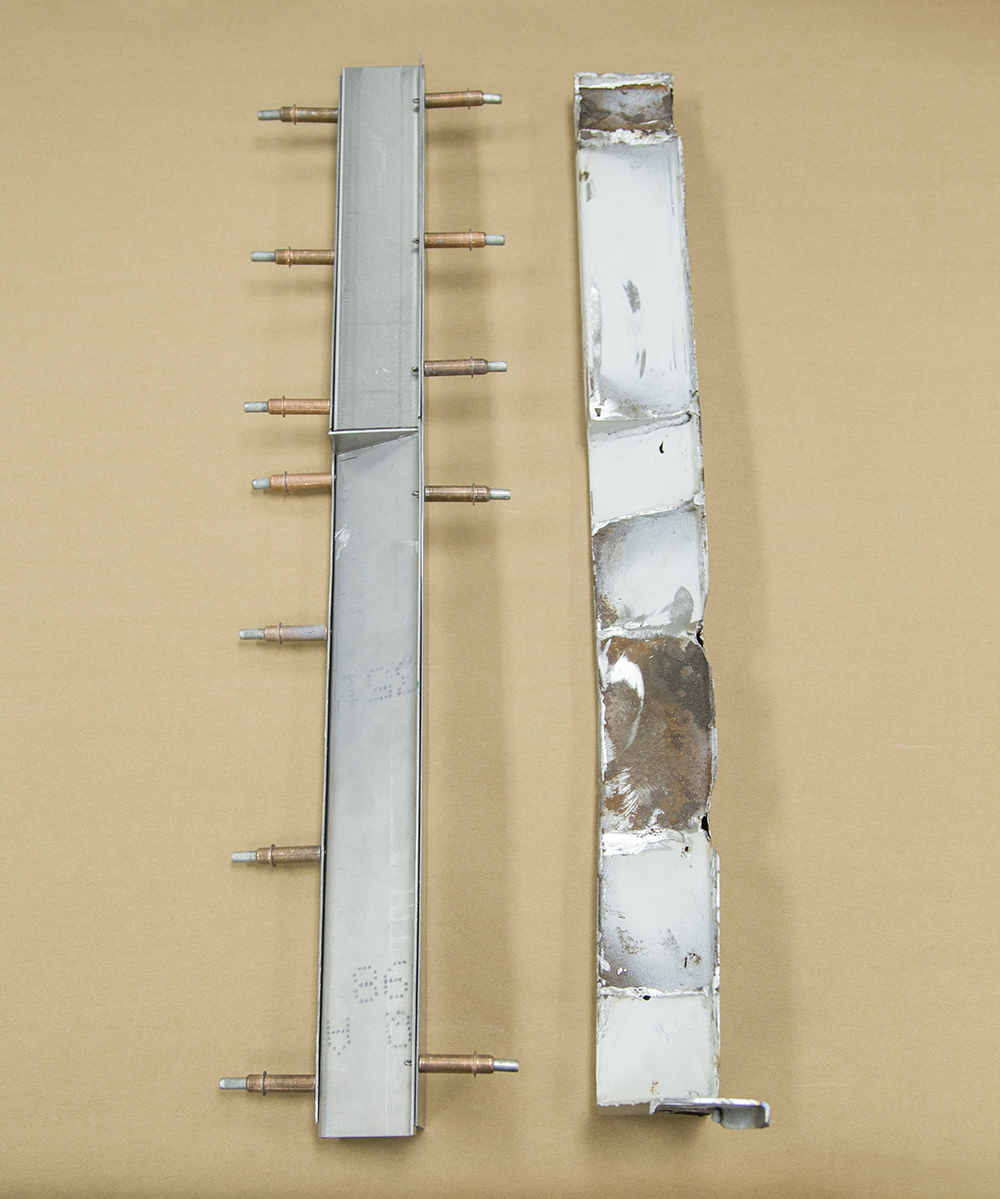
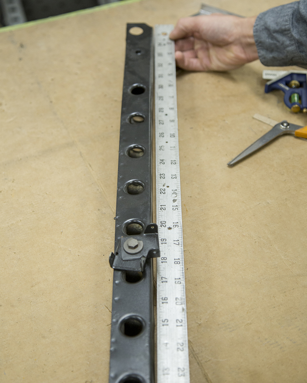
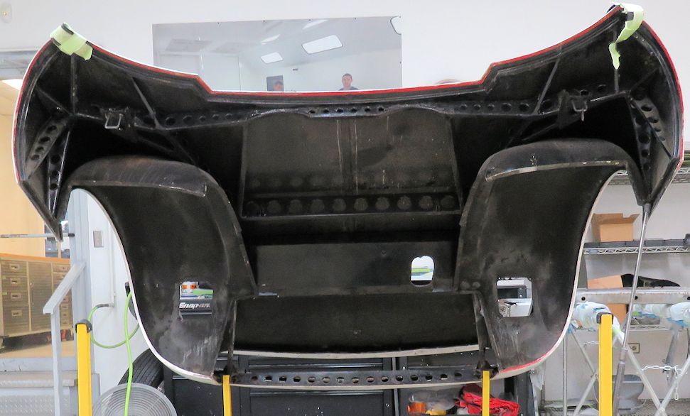
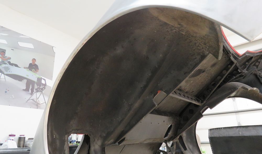
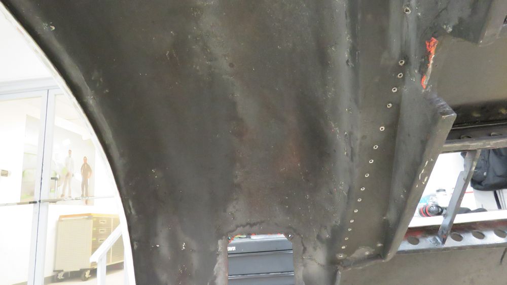
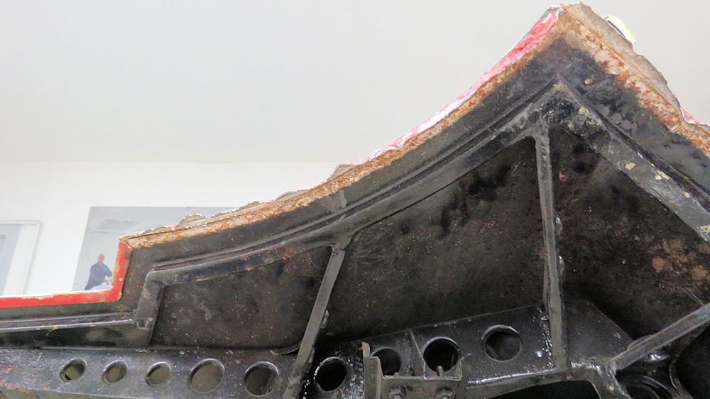
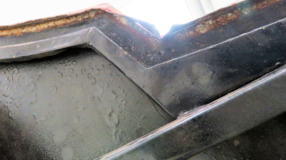
De-skinning the
engine cover has revealed a fair amount of galvanic
corrosion everywhere that the aluminum skin came into
contact with the steel frame.
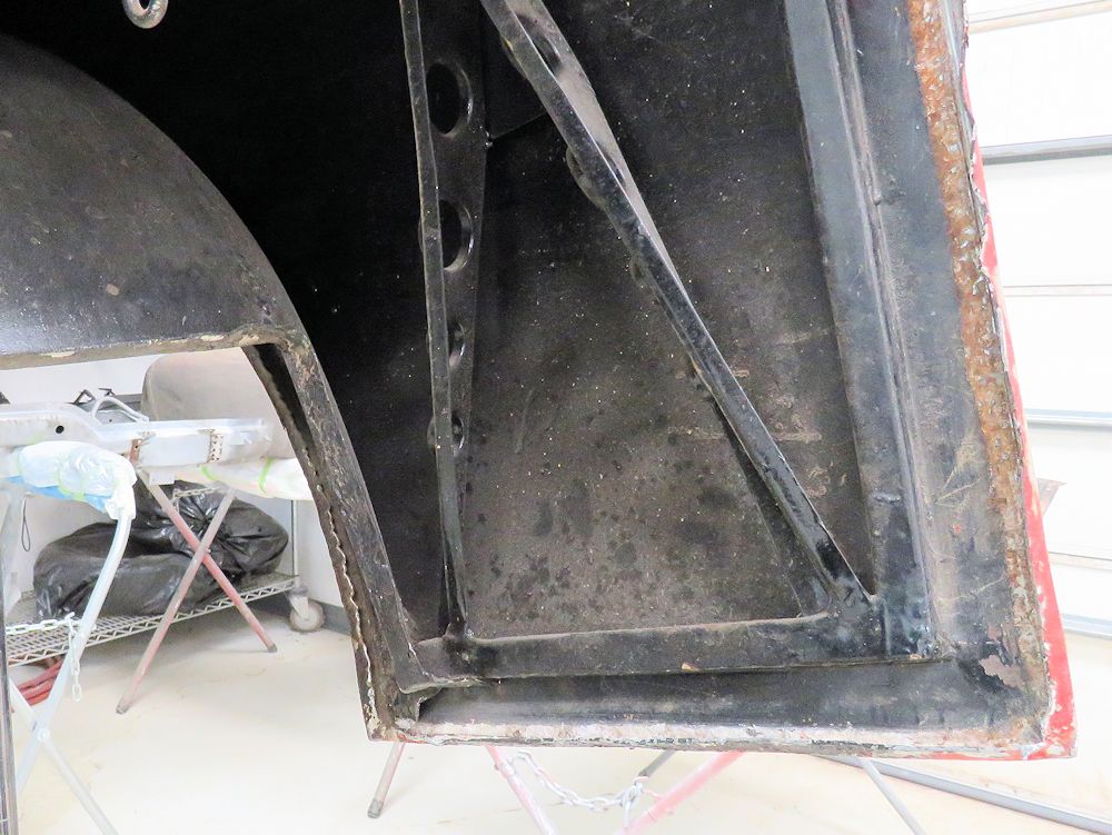
Rarely seen steel structure that supports the
aluminum outer skin
The rear cover skin weighs a mere 21 lbs
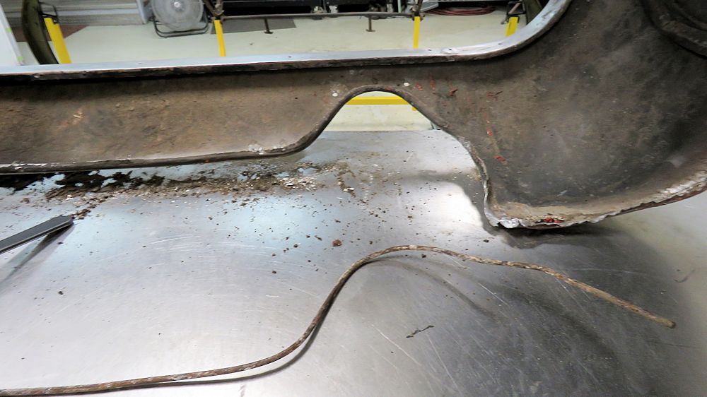
Removing the steel wire from the bottom edge
of
the allow panel
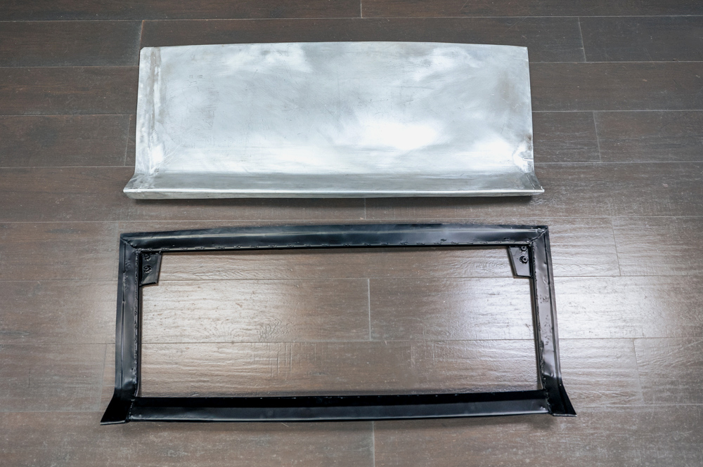
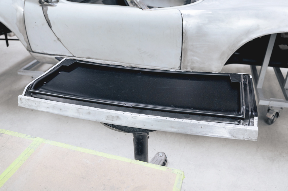
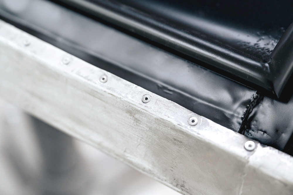
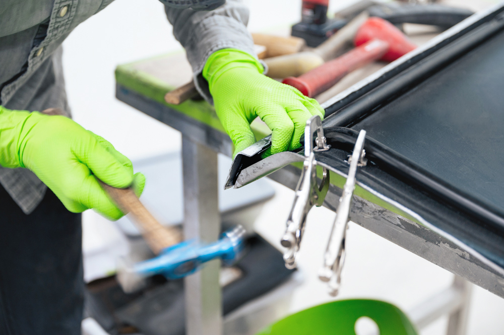
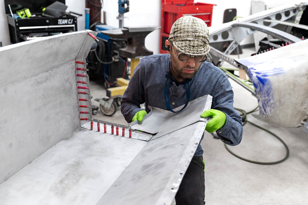
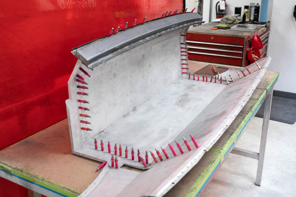
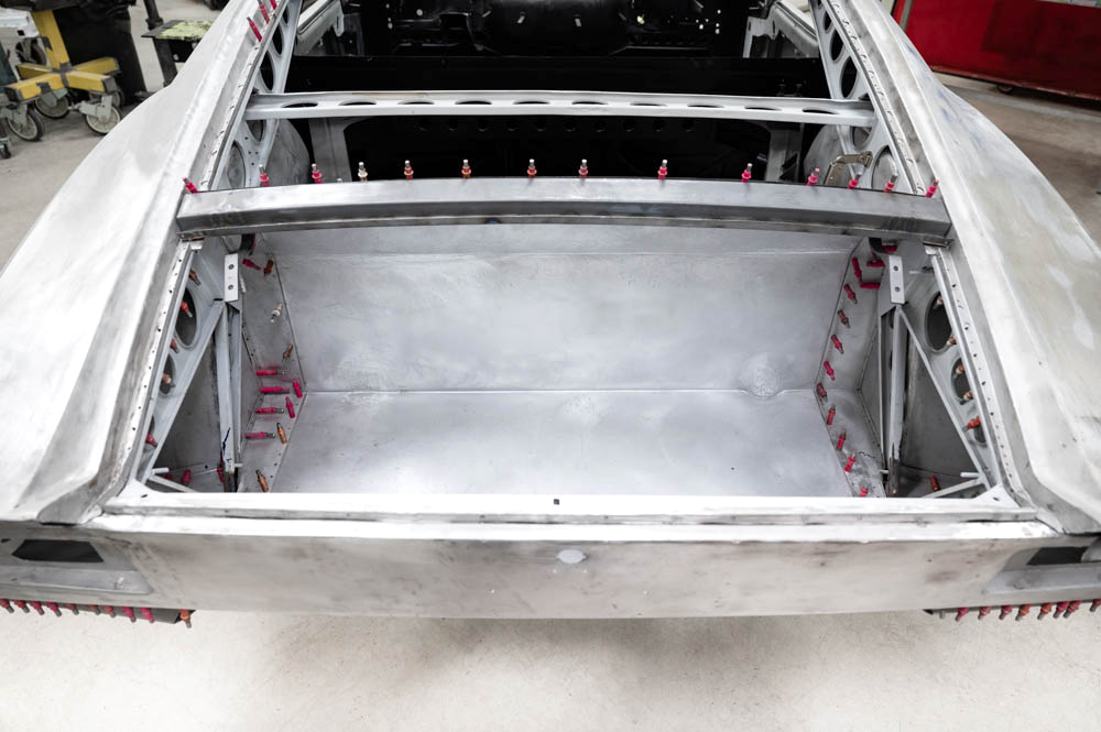
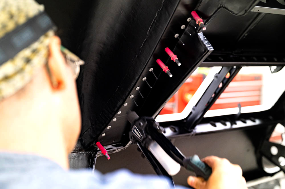
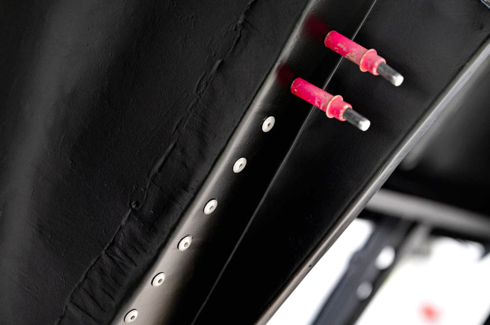
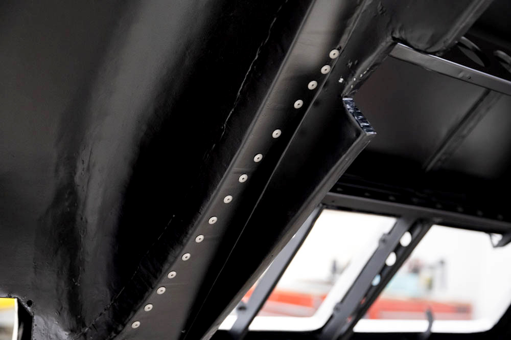
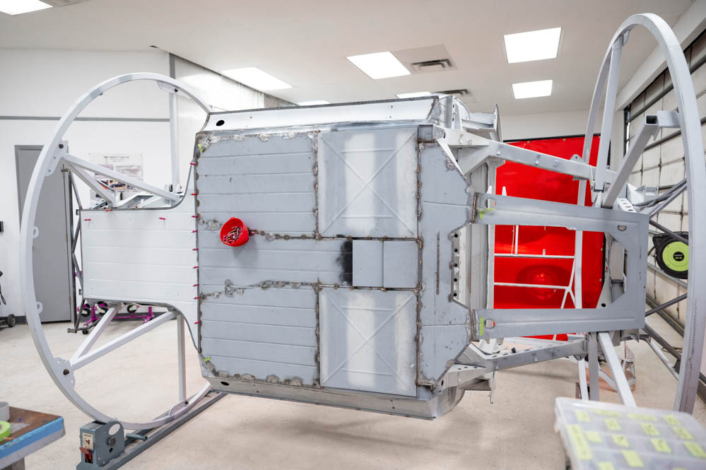
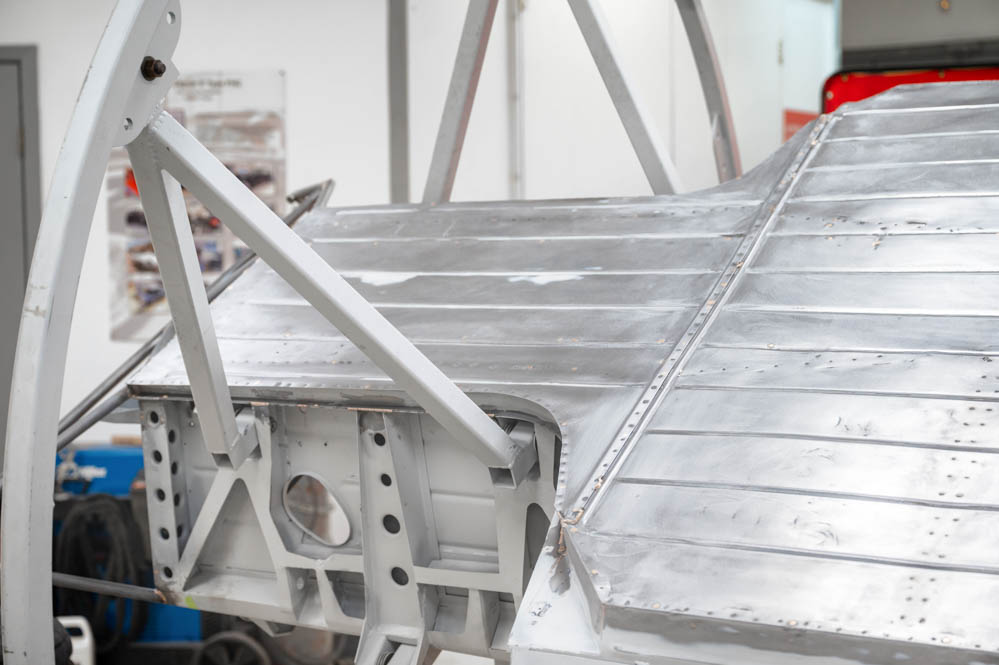
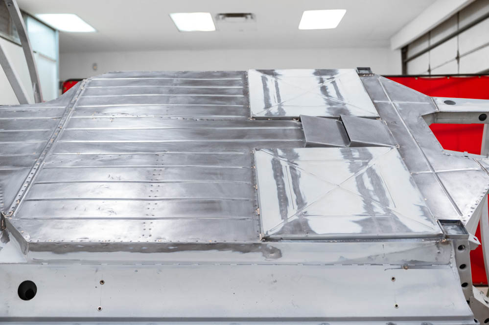
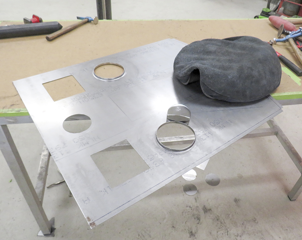
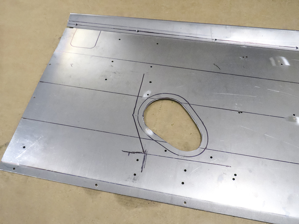
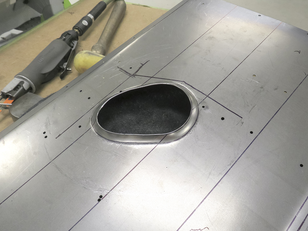
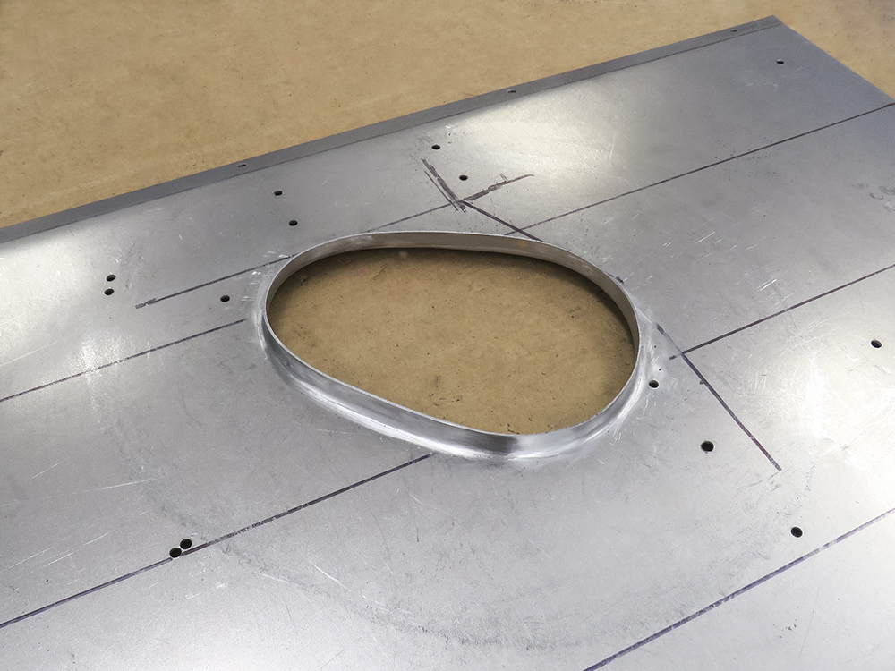
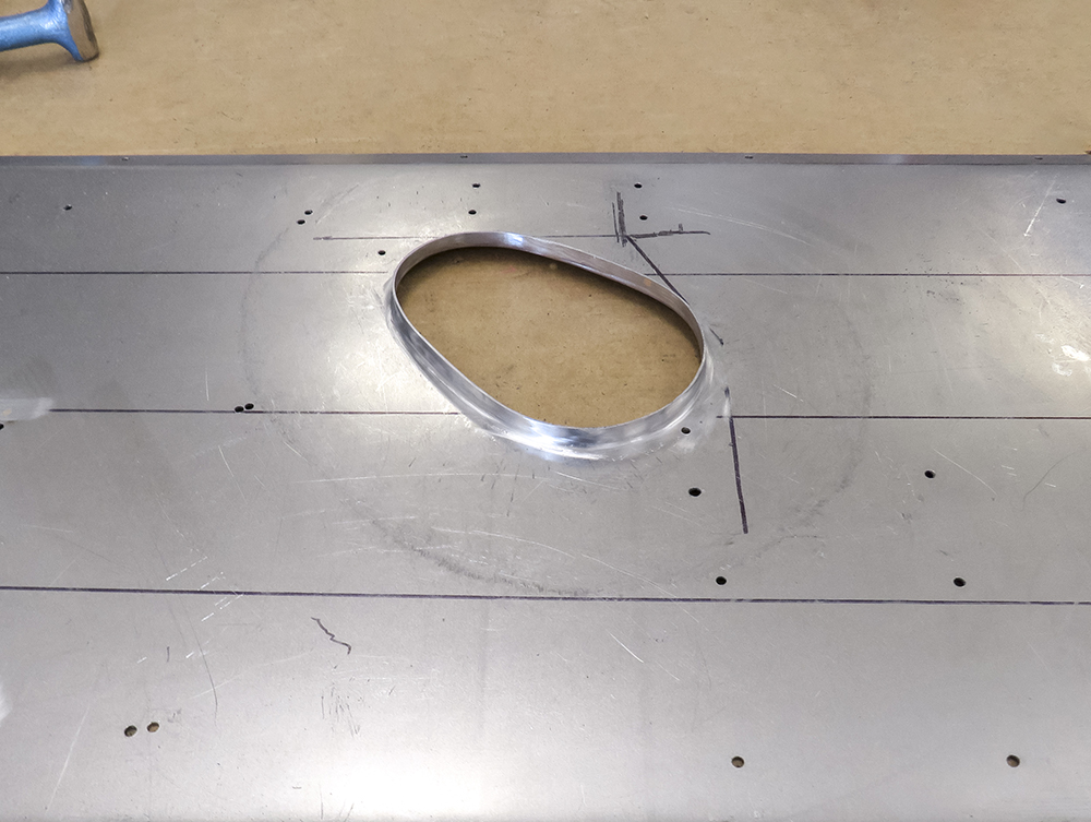
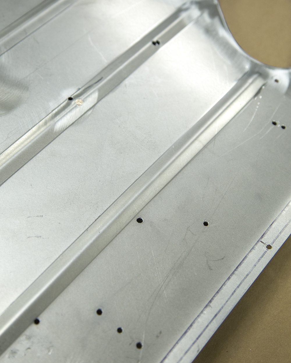
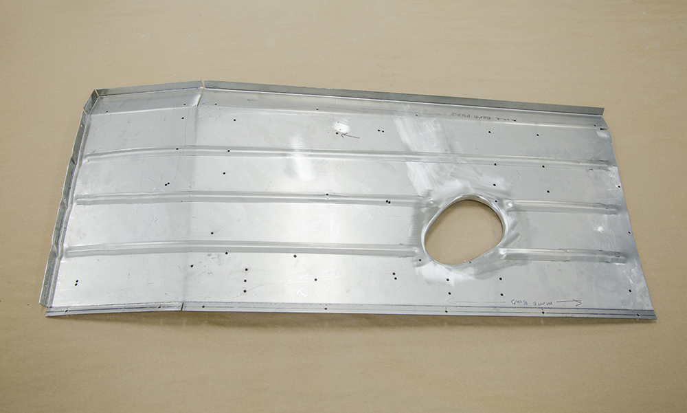
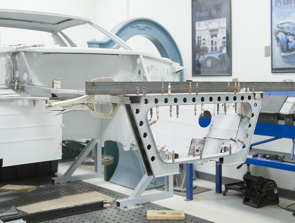
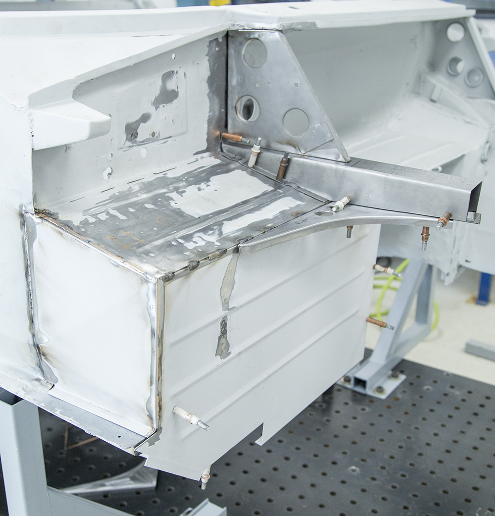
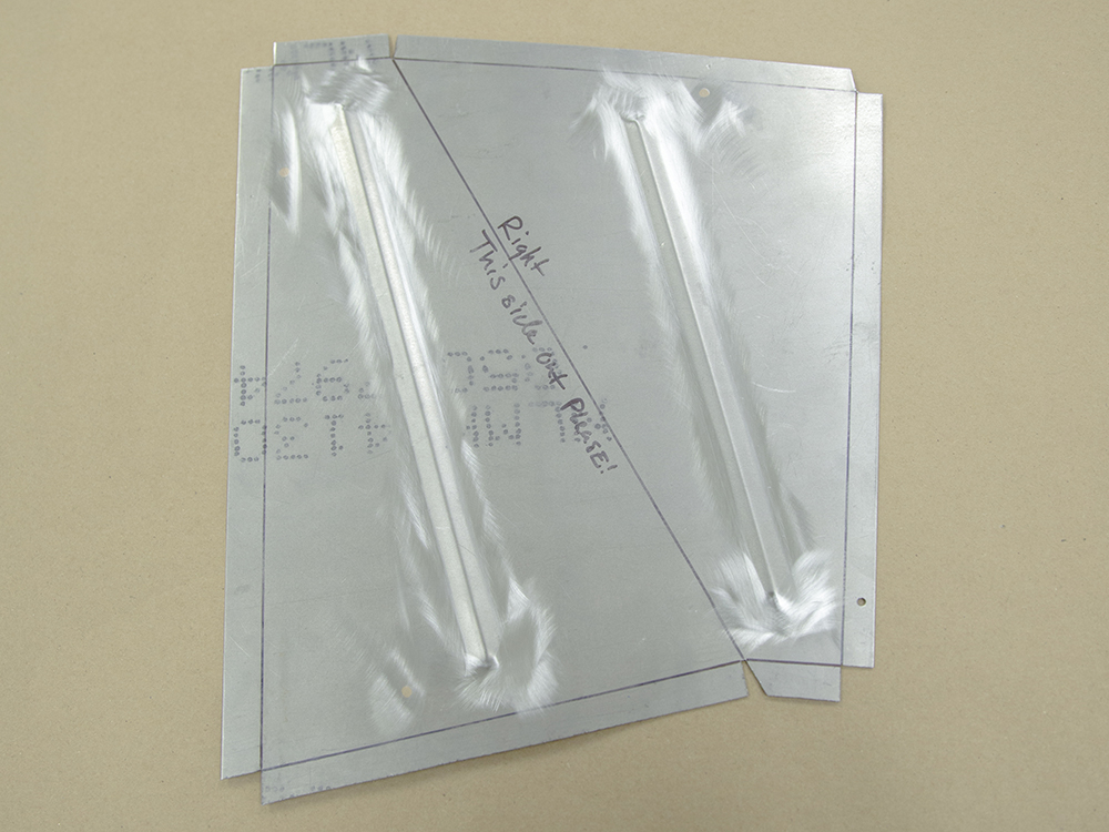
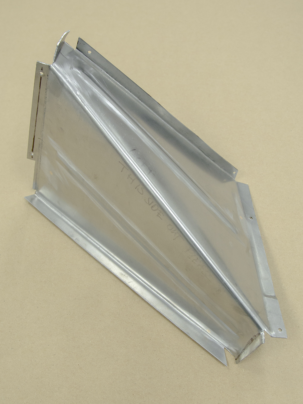
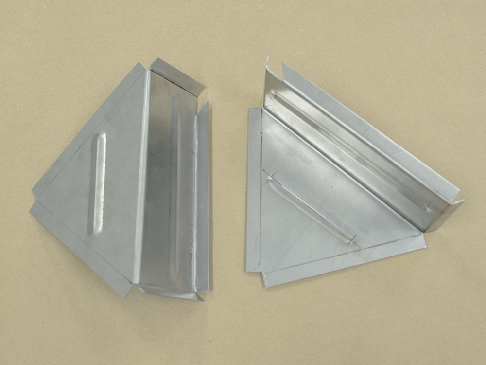
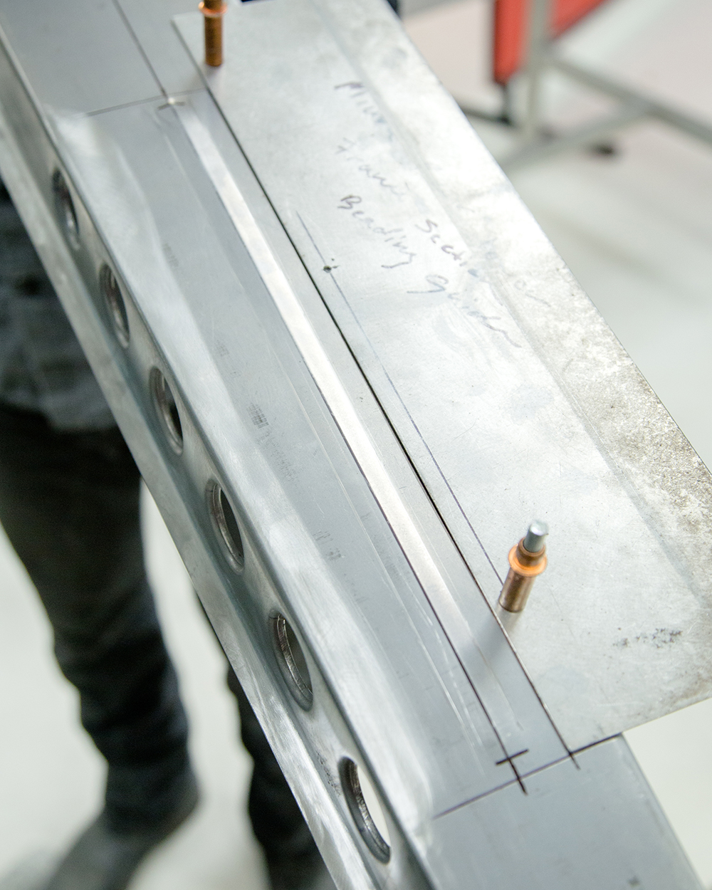
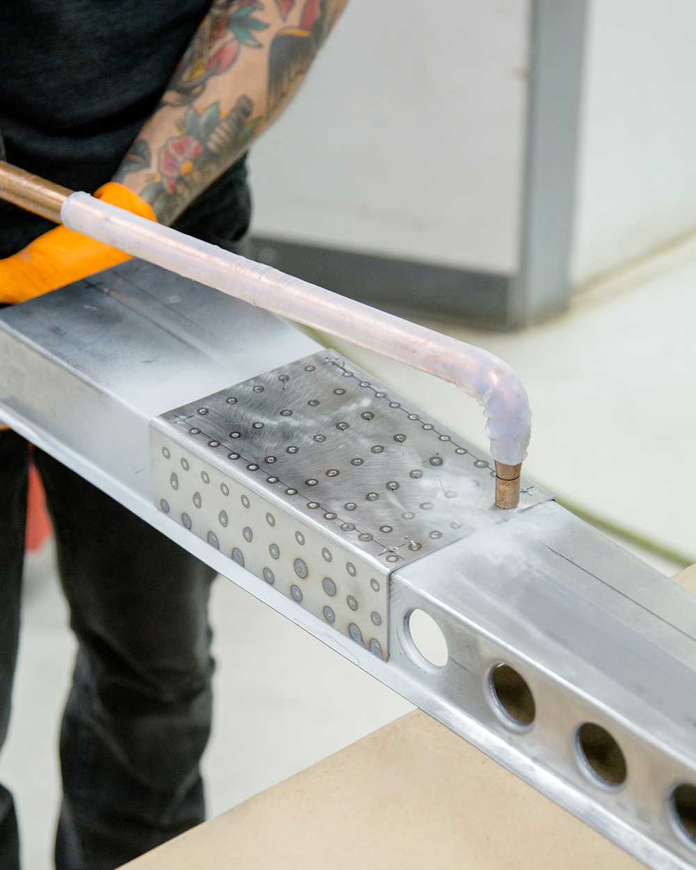
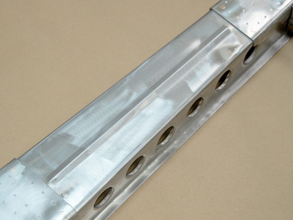
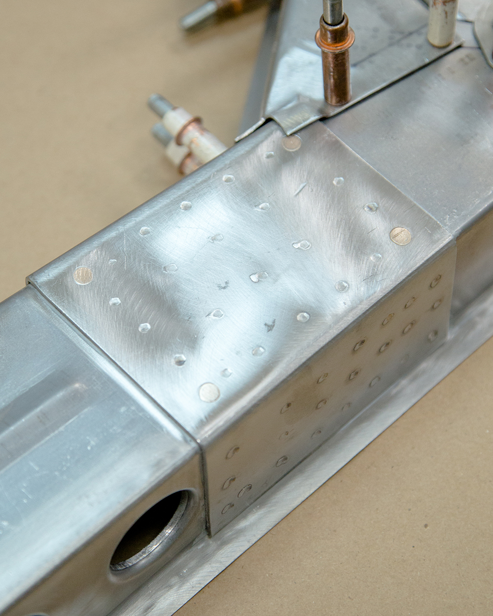
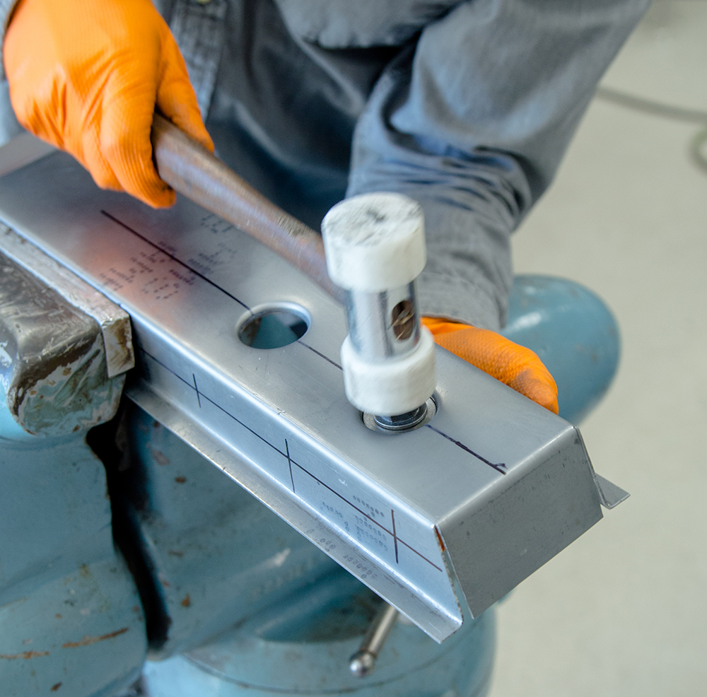
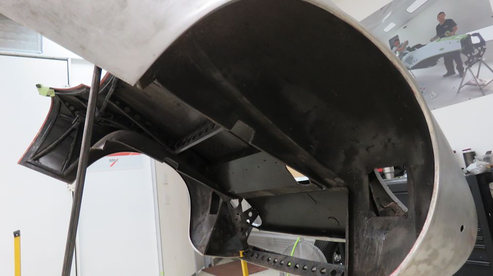
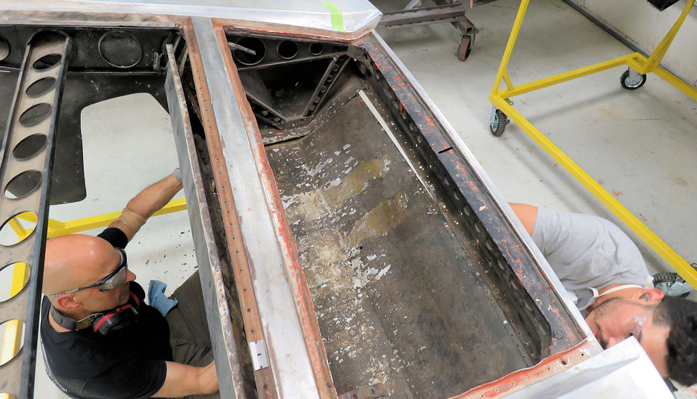
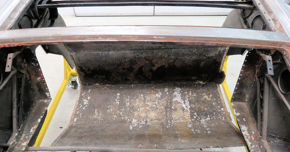
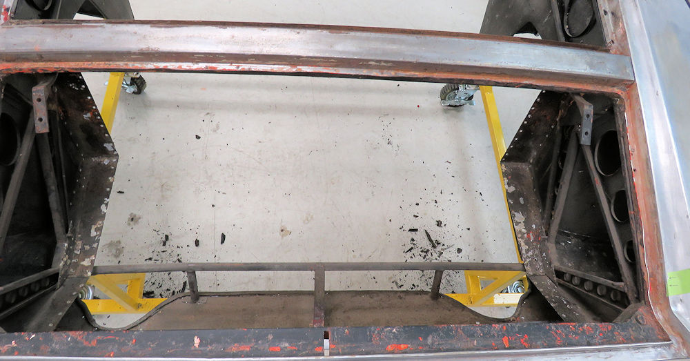
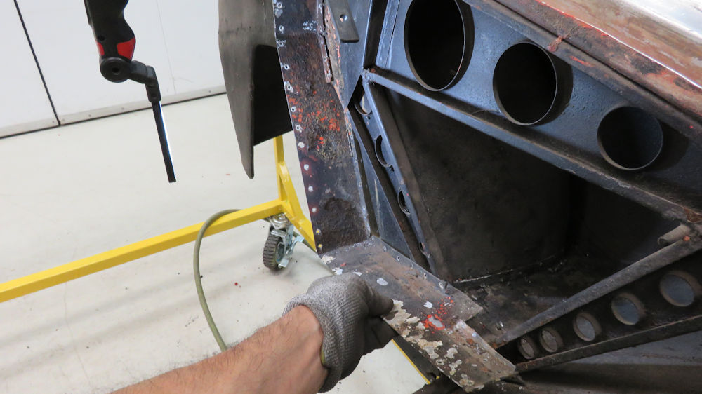
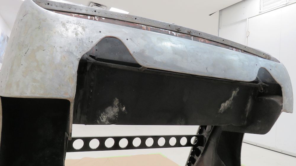
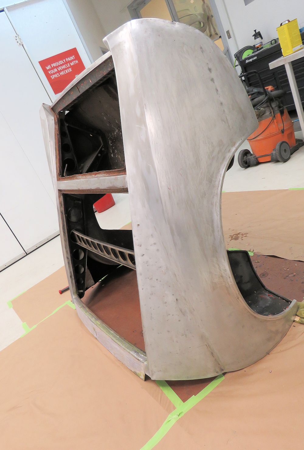
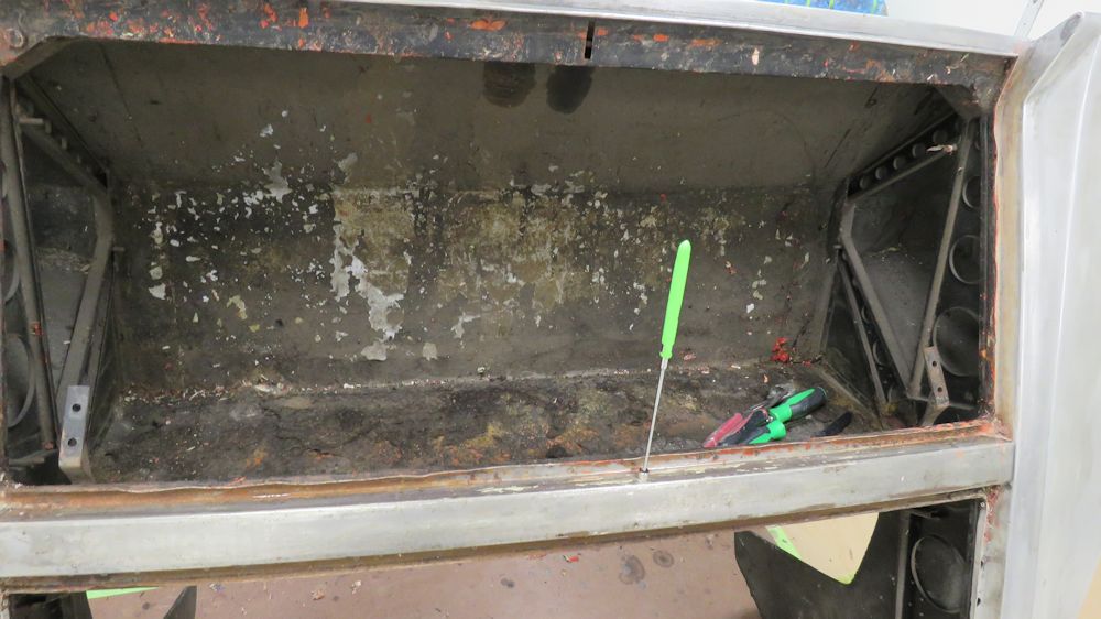
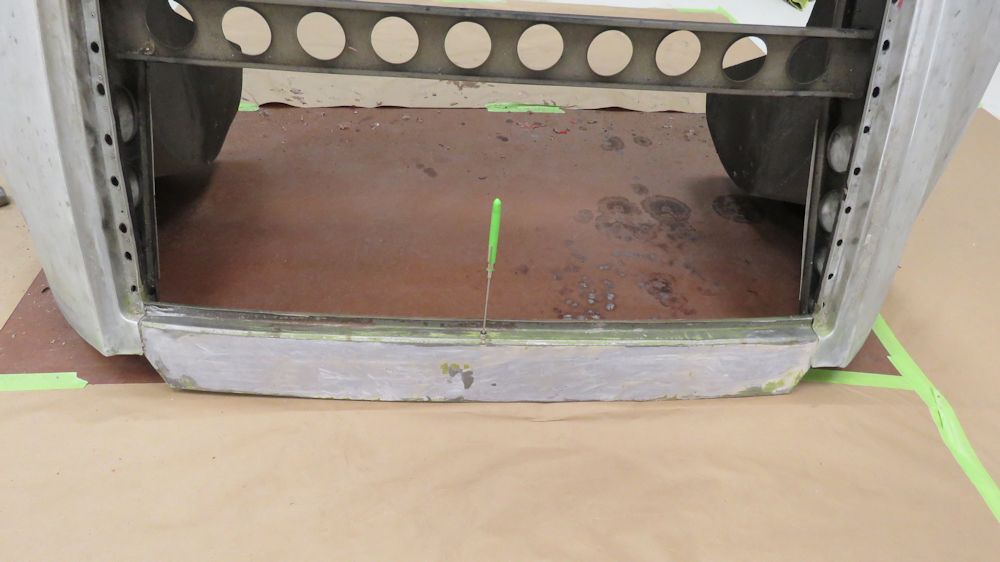
Removing the
aluminum boot floor assembly and corresponding inner wheel
arch panels. The boot floor was held in place with 132
rivets.
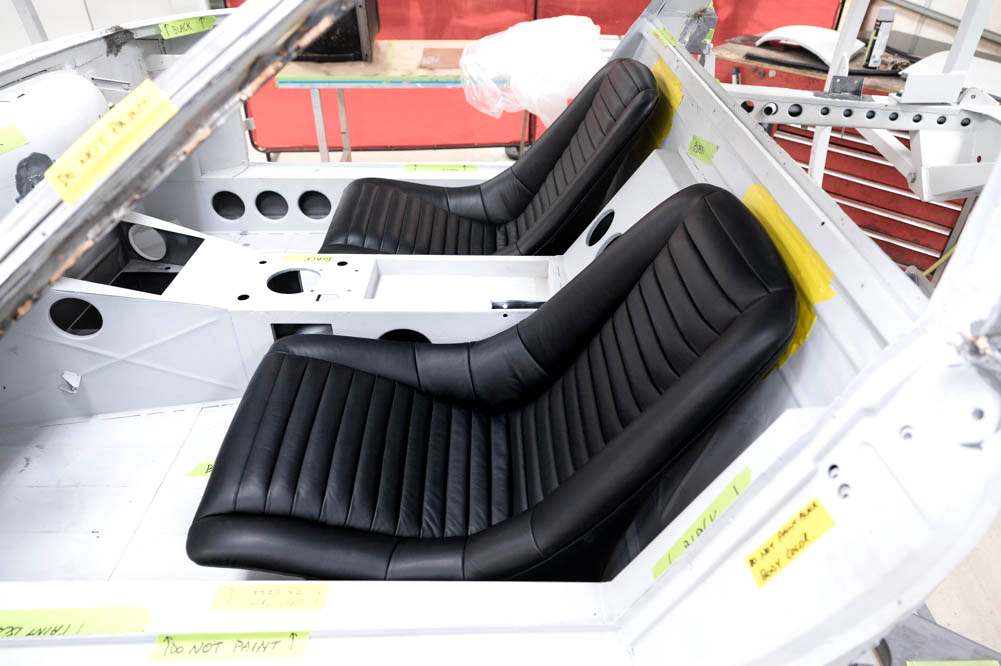
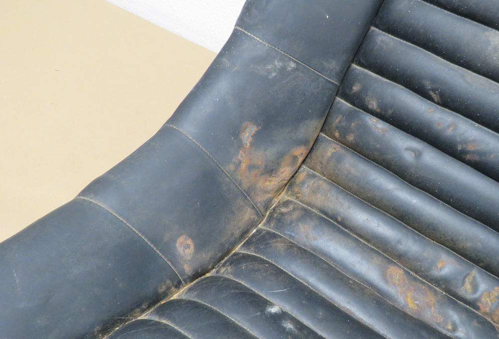
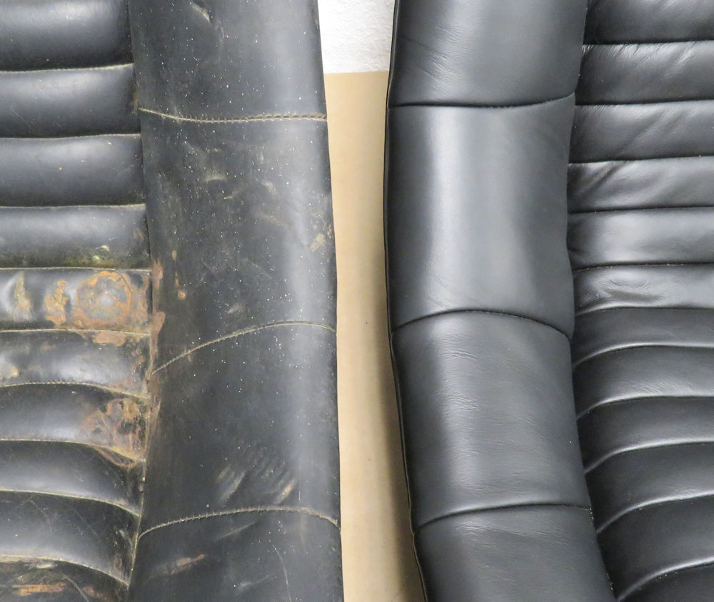
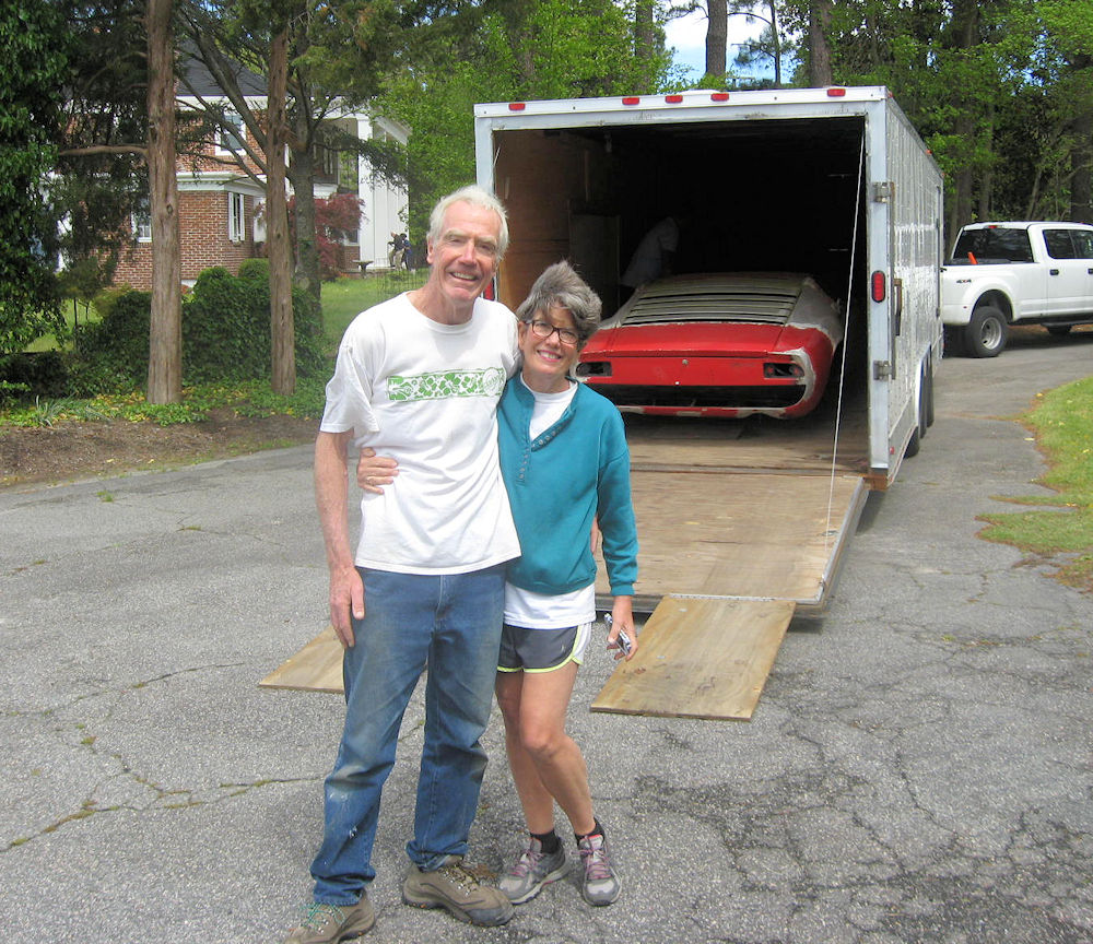
Yesterday we were
delighted to receive a visit from Topo's owners. Rob and Jan
visited the Team CJ Workshop to deliver a van load of spare
parts and to check in on progress with the Miura. Among the
many boxes of parts were Topo's original seats which had
been restored and re-trimmed in Michigan in 1984.
Interestingly, there was also a spare (third) Miura seat
still in its original hide cover, so we were able to compare
the untouched original seat with the restored seats. The
Michigan trimmer did an outstanding job and replicated the
original factory padding and stitching extremely well
indeed. Thankfully, Rob and Jan also did a great job of
protecting and storing the restored seats in the ensuing 35
years, so they remain in perfect condition to this day!
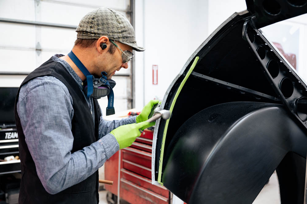
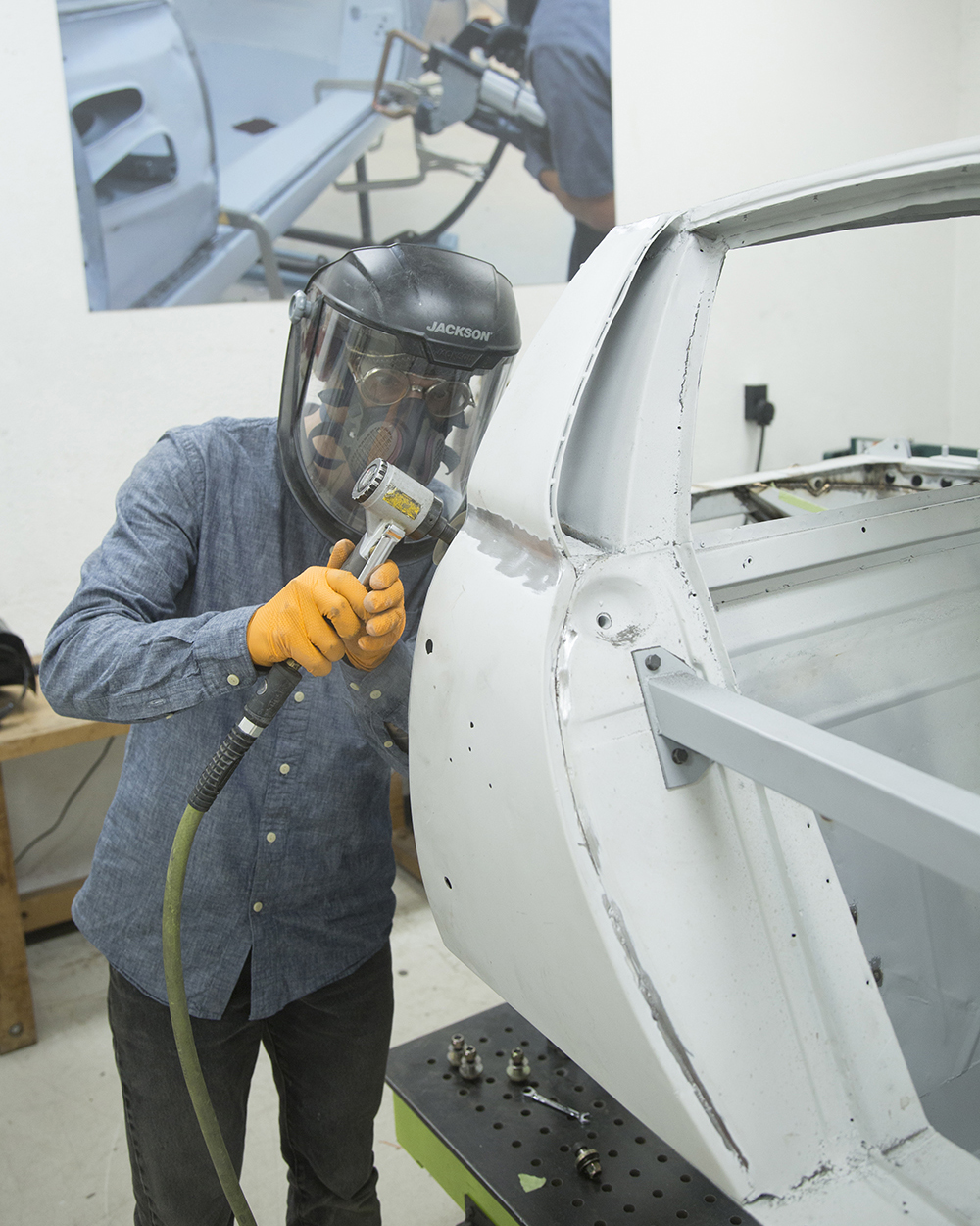
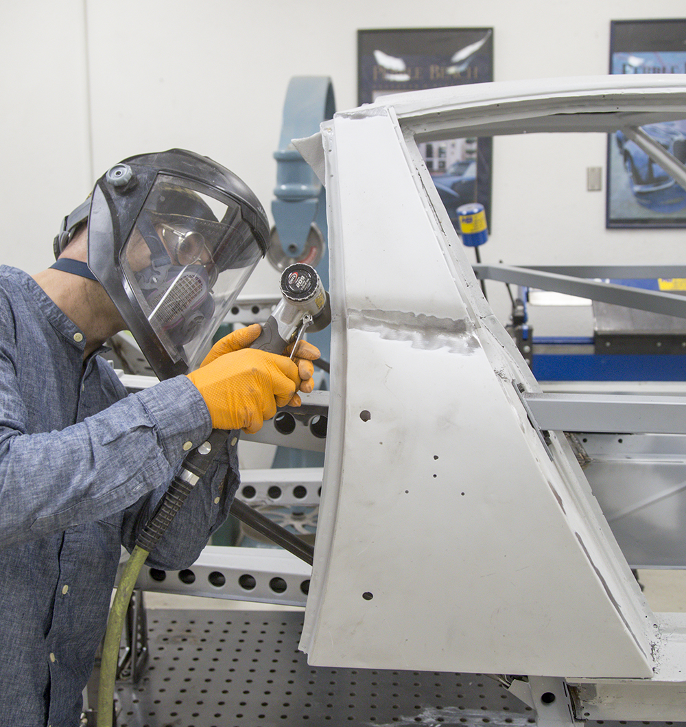
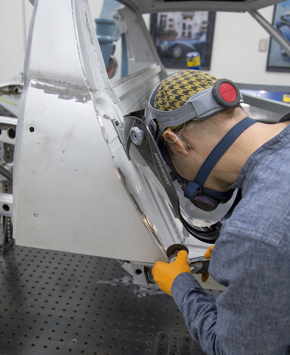
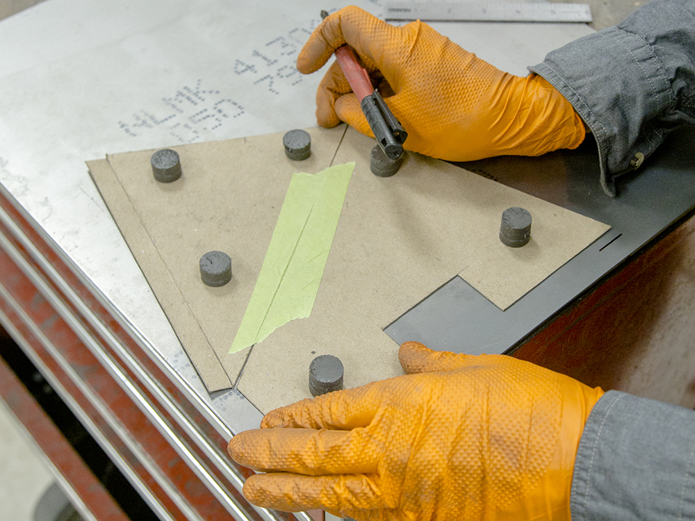
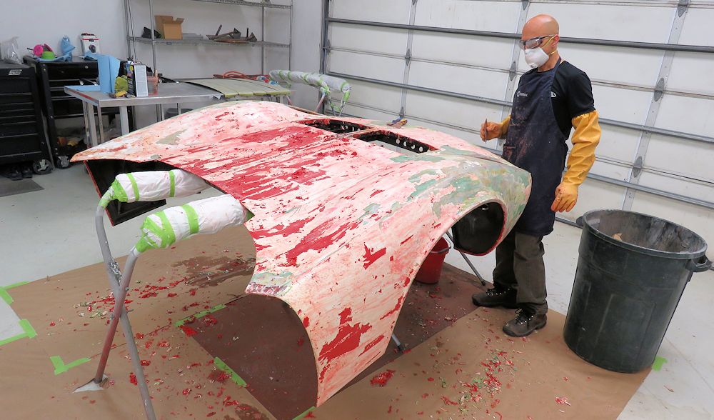
The first few photographs in the sequence below show Francis
stripping the bonnet back to bare aluminum. The fourth image
shows galvanic corrosion at the right/rear edge of the
bonnet.
Francis stripping the paint and primer from
the bonnet
The green layer is an etching primer that
adheres
extremely well to the aluminum
Typical galvanic corrosion where aluminum
meets steel
Bonnet is now stripped to bare aluminum
Rob and Jan checking in on Topo
An original factory Miura bucket street
Interesting to observe the original factory
trimwork
Note how the factory finished the trimming
beneath
the seat base
Topo's seats were restored in 1984
Comparing Topo's restored seats with the
original
I'd say the trimmer did a superb job back in
1984!
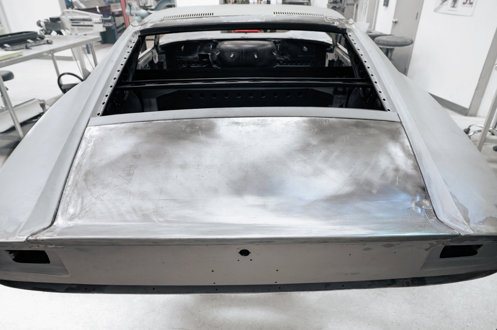
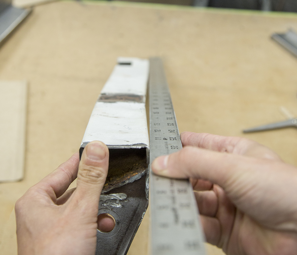
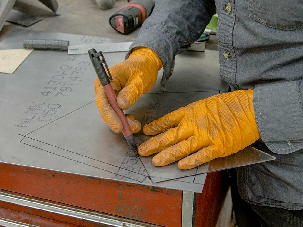
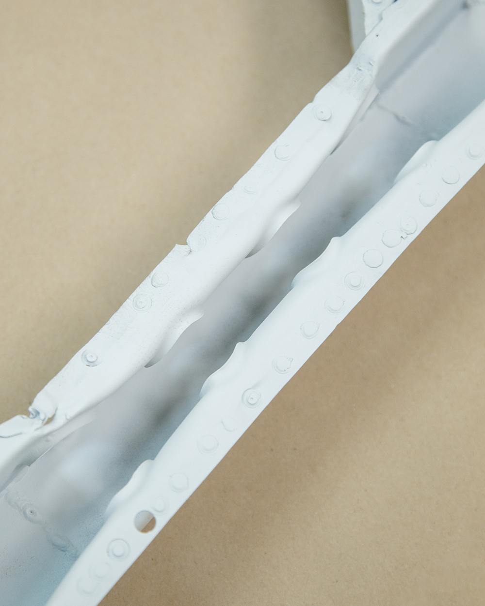
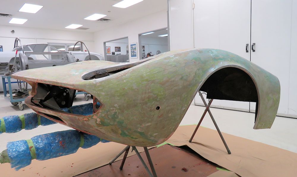
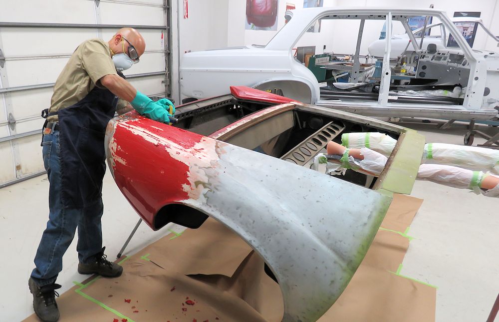
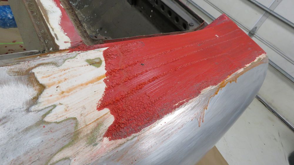
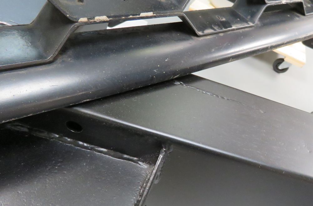
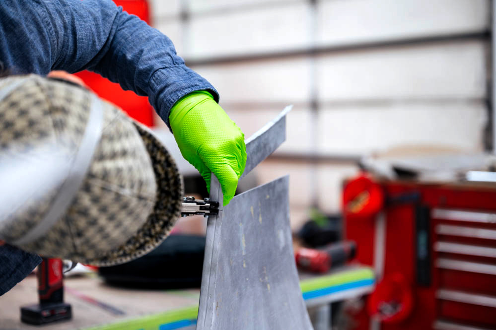
The following
sequence of photos show Francis stripping the paint, primer
and filler from the rear clip. The rear wings and boot
compartment are aluminum, whereas the transverse braces
running across the body are steel.
Francis using 'aircraft stripper' to remove
paint
and primer by hand
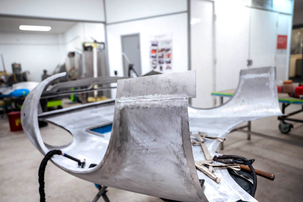
It looks very much like factory primer and one
coat of paint
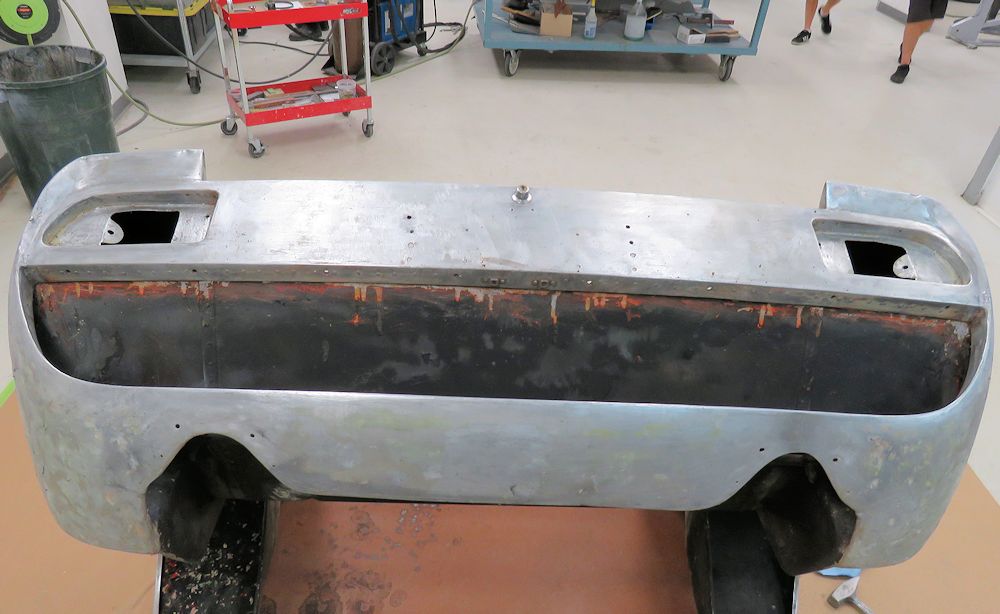
The aluminum panels that form the rear clip
have
suffered only very minor damage
Note magnet attached to the steel brace panels
The panel behind the rear window is also steel
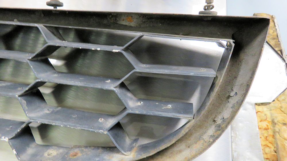
Time to strip the bonnet!
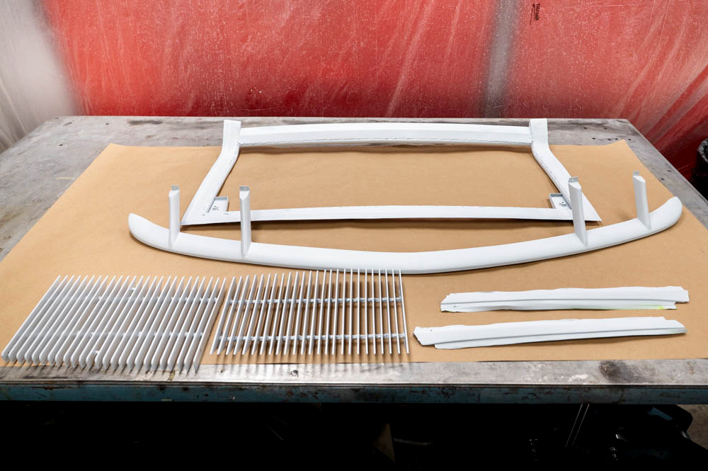
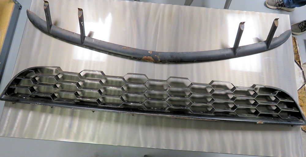
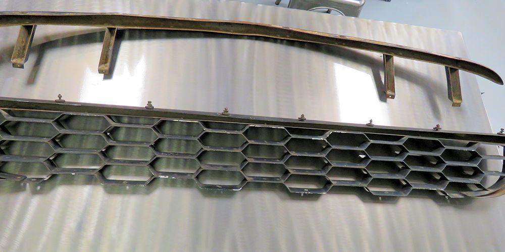
Rear bumper grille appears to be in its
original finish
Interesting that it does not have the hardwood
insert
noted in chassis # 3186 (also a 1967 P400)
Comparing the original 'satin' finish to a
traditional 'chassis black'
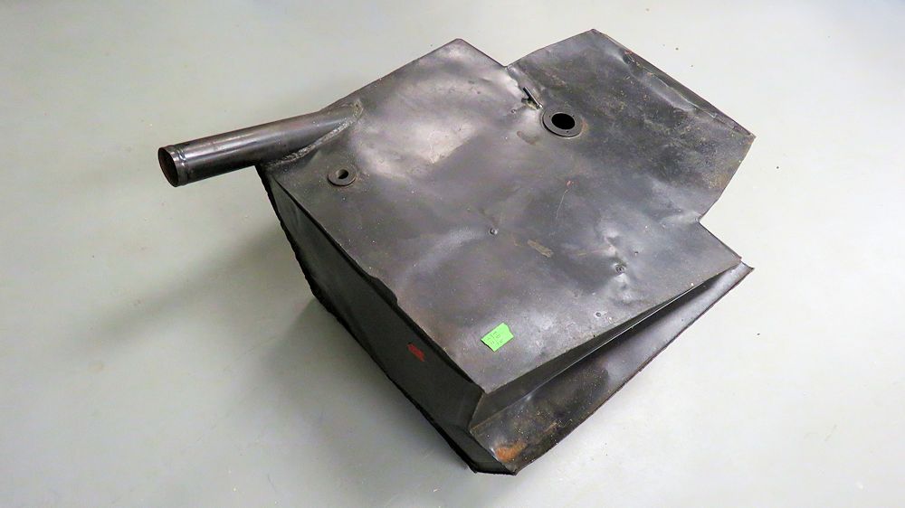
Fuel tank is not in great condition and will
be replaced
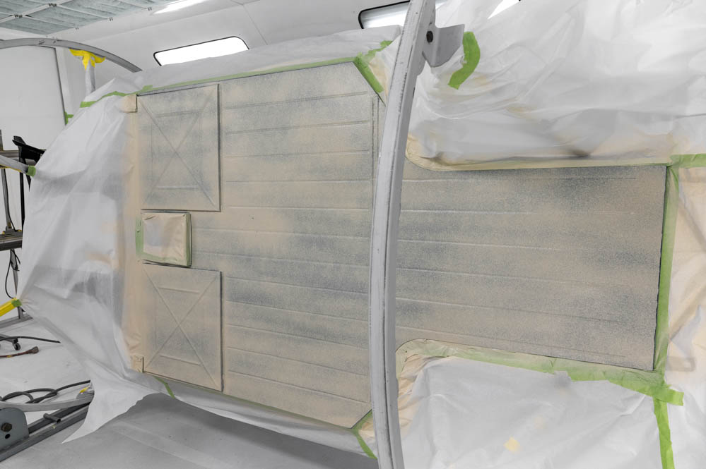
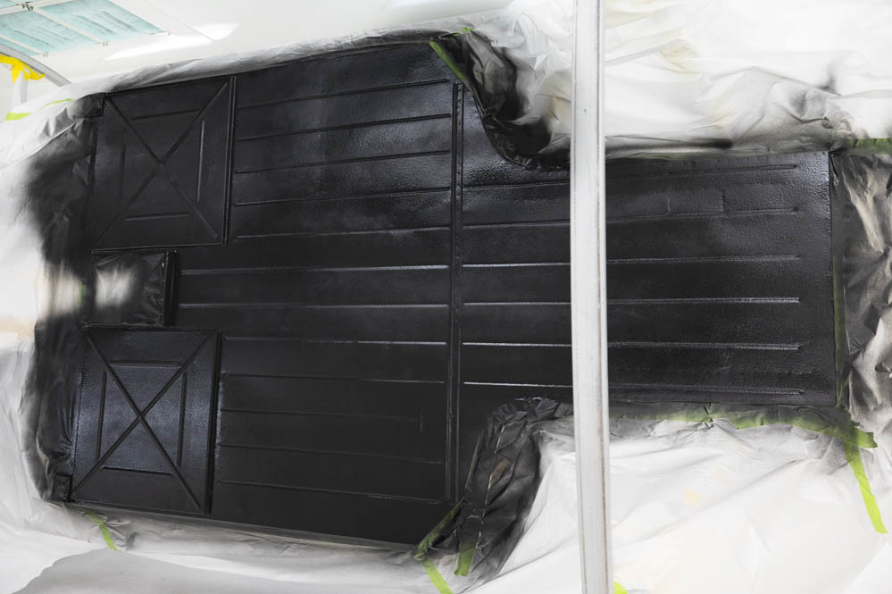
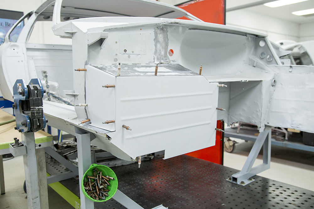
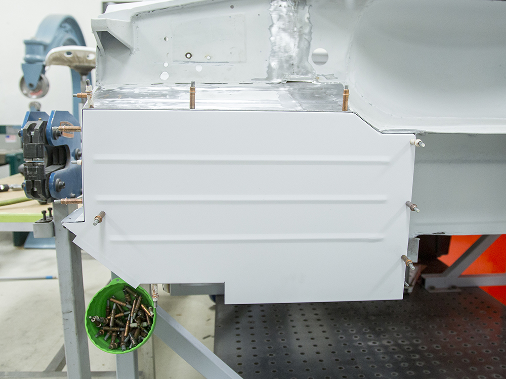
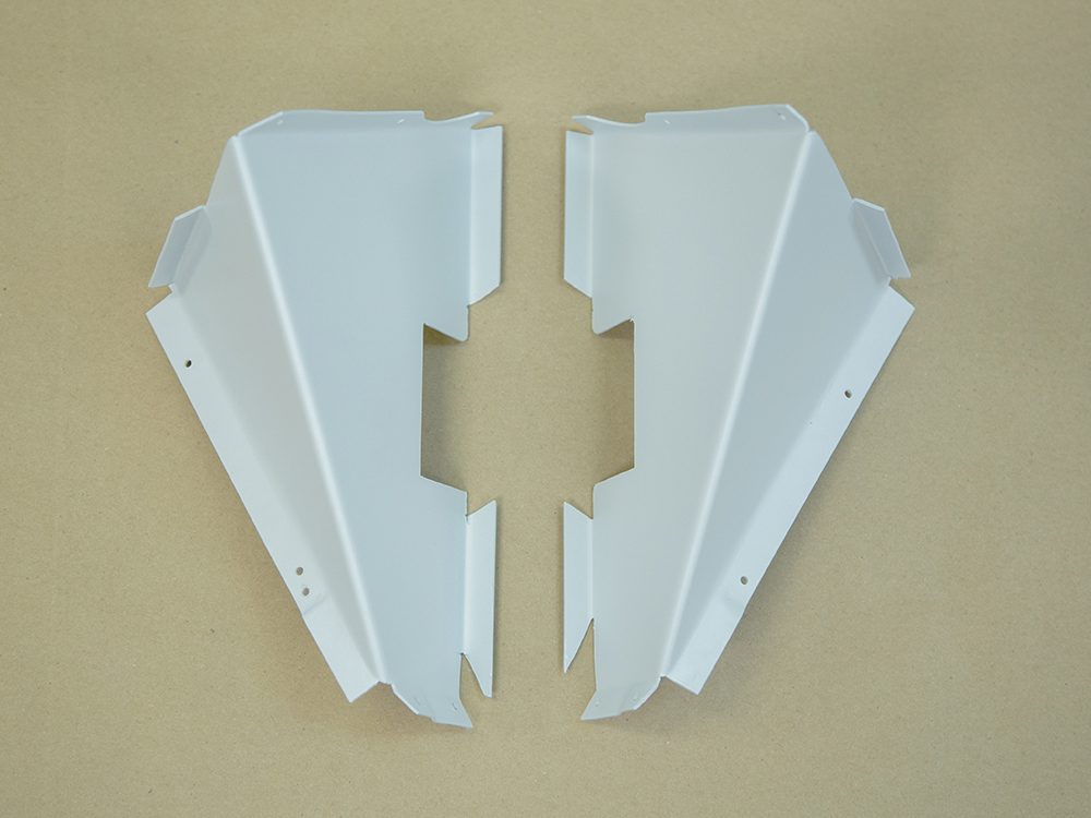
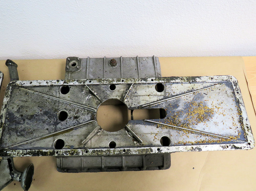
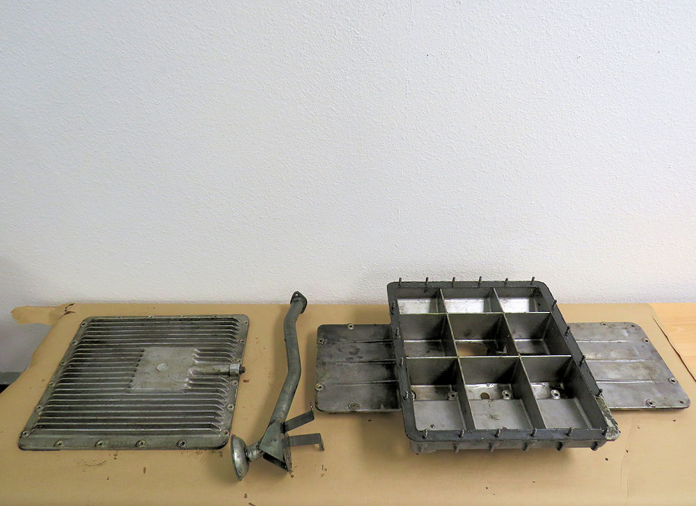
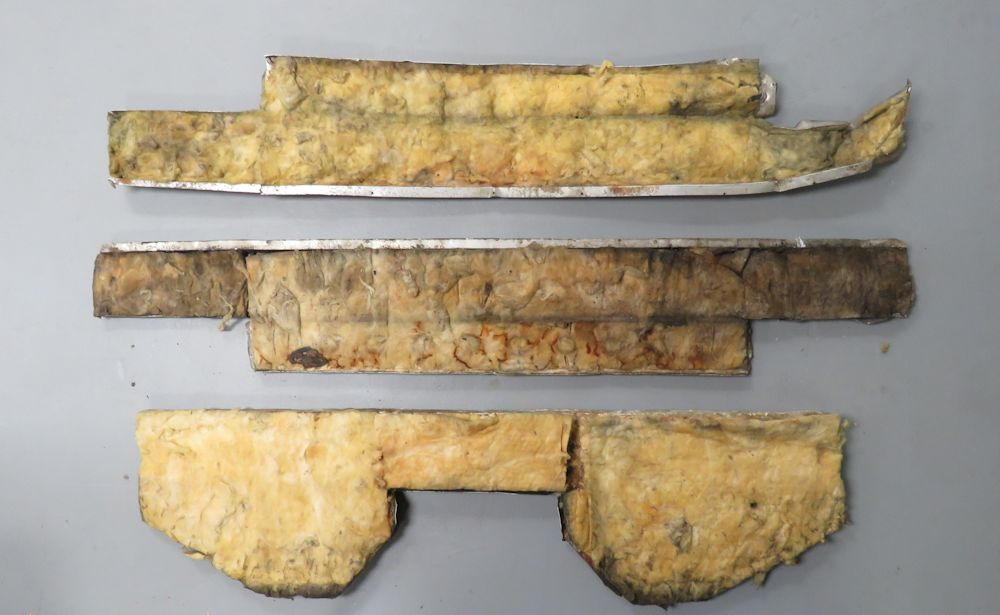
Insulating panels
Off the road
since 1980, this 1967 Lamborghini Miura P400, affectionately
known as 'Topo', is about to undergo a total restoration in
the Team CJ Works.
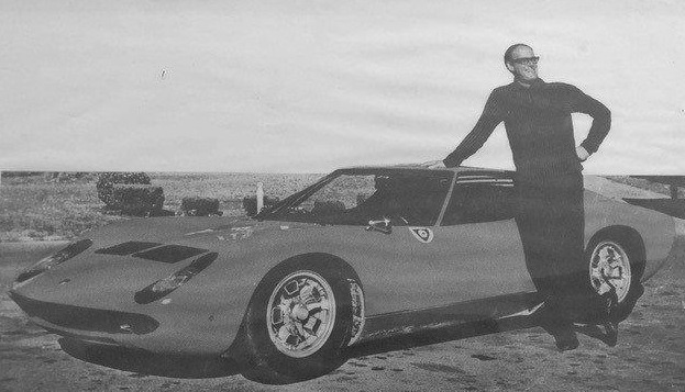
The first owner of this special
car was legendary racer, collector, raconteur, author and
car guy extraordinaire, Toly Arutunoff. Mr. Arutunoff bought
the car new in 1967 and immediately took it racing - because
that's the type of thing he did!
Toly Arutunoff with Topo in 1967
Only Toly Arutunoff would buy a brand new
Miura
and take it straight to the track!